Walker Walker Mowers User manual

OPERATOR’S MANUAL
Safety,Assembly, Operating, and Maintenance Instructions
Model MBS29
Please Read and SaveThese Instructions Beginning S/N: 125598
For Safety, ReadAll Safety and Operation Effective Date: 01-09-12
Instructions Prior to Operating Machine P/N 2000-7

Foreword
Thank you. . .for purchasing a Walker mower. Every effort has been made to provide you with the
most reliable mower on the market, and we are sure you will be among our many satised custom ers.
Iffor anyreasonthisproductdoesnotperformtoyourexpectations,please contactyourlocaldealer.
Every customer is important to us. Your satisfaction is our goal.
Please. . .read this manual thoroughly! This manual is to be used in conjunction with the engine
manufacturer’s manual for the specic engine on the mower model you have purchased. Before you
operateyournewmower,pleaseread this entiremanual. Someoftheinformation is crucialforprop-
er operation and maintenance of this mower - it will help protect your investment and ensure that the
mower performs to your satisfaction. Some of the information is important to your safety, and must
be read and understood to help prevent possible injury to the operator or others. If anything in this
manual is confusing or hard to understand, please contact your local authorized dealer or call our
service department, at (970) 221-5614, for clarication before operating or servicing this mower.
This manual covers Model MBS29 with the Kohler ECH749 (29 HP) Electronic Fuel Injection (EFI)
gasoline engine.
All shields and guards must be in place for the proper and safe operation of this machine.
Where they are shown removed in this manual, it is for illustration purposes only. Do not operate
this machine unless all shields and guards are in place.
Specications given are based on the latest information available at the time this manual was pro-
duced for a tractor with standard equipment. Optional equipment is available and may affect the
standard specications listed.
Walker Mfg. Co. is continually striving to improve the design and performance of its products. We
reserve the right to make changes in specications and design without thereby incurring any obli-
gation relative to previously manufactured products.
Sincerely,
WALKER MANUFACTURING COMPANY
Bob Walker, President

Table of Contents
General Information ________________ 1
HIGHLIGHTED INFORMATION _____________ 1
GLOSSARY ____________________________ 1
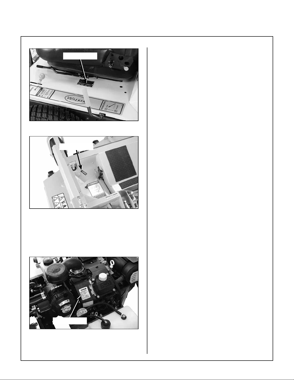
IDENTIFYING NUMBER LOCATIONS ________ 1
ENGINE SERIAL NUMBER LOCATION_______ 2
SERVICING OF ENGINEAND
DRIVETRAIN COMPONENTS ______________ 2
Specications________________________ 3
ENGINE________________________________ 3
ELECTRICAL SYSTEM ___________________ 3
TRANSMISSION_________________________ 3
BLADE DRIVE __________________________ 4
TIRE SIZE ______________________________ 4
TIRE PRESSURE ________________________ 4
DIMENSIONS ___________________________ 4
CURB WEIGHT__________________________ 5
DRIVE BELTS___________________________ 5
SEAT__________________________________ 5
FRAME/BODY CONSTRUCTION____________ 5
DECK CHART___________________________ 5
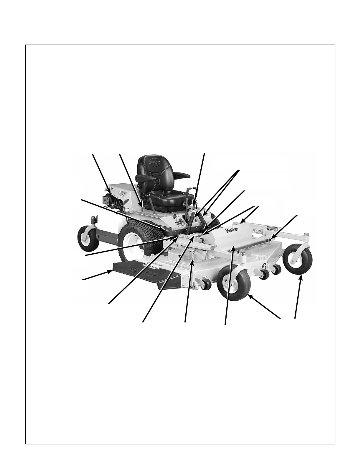
Component Identication ___________ 6
Safety Instructions __________________ 9
BEFORE OPERATING ____________________ 9
OPERATING ___________________________ 11
MAINTENANCE ________________________ 13
SAFETY, CONTROL,AND
INSTRUCTION DECALS _________________ 14
Assembly Instructions______________ 18
SETUP INSTRUCTIONS__________________ 18
Battery Service _______________________ 18
Wet Battery Service __________________ 18
Dry Battery Service___________________ 18
Battery Charging_____________________ 19
Mower DeckAssembly_________________ 19
Deck Caster Wheels Installation_________ 19
Deck Discharge Deector
Shield Installation ____________________ 20
PTO Shaft Guard Installation ___________ 20
Tilt-Up Roller Wheel Installation _________ 20
Mower Deck Installation on Tractor_______ 21
Deck Installation _____________________ 21
Deck Leveling_______________________ 23
PREOPERATING CHECKLIST_____________ 24
Operating Instructions_____________ 26
CONTROL IDENTIFICATION,
LOCATION,AND FUNCTION _____________ 26
Ignition Switch _______________________ 26
Engine Throttle_______________________ 27
Body Latch __________________________ 27
Forward Speed Control (FSC) ___________ 27
Steering Levers_______________________ 28
Blade Clutch (PTO)____________________ 28
Parking Brake ________________________ 28
Oil Pressure Warning Light _____________ 29
Engine Service Light __________________ 29
Over Temperature Warning Light ________ 29
Transaxle Lockout Rods _______________ 30
Hourmeter___________________________ 30
STARTING THE ENGINE _________________ 32
ADJUSTING GROUND
SPEEDAND STEERING__________________ 32
ENGAGING THE BLADE DRIVE ___________ 34
STOPPING THE MACHINE _______________ 35
FUEL SELECTOR VALVE_________________ 36
ADJUSTING CUTTING HEIGHT____________ 36
Transport Position ____________________ 36
TRANSAXLE LOCKOUTS ________________ 37
RECOMMENDATIONS FOR MOWING ______ 37
RECOMMENDATIONS FOR TILT-UP DECK
OPERATION/TRANSPORT _______________ 39
Maintenance Instructions __________ 40
MAINTENANCE SCHEDULE CHART _______ 40
IMPORTANT TIPS FOR CARE OF THE
KOHLER ENGINE_______________________ 41
Fuel System _________________________ 41
Starting/Stopping_____________________ 41
Cooling System ______________________ 41
Air Cleaner System____________________ 41
Oil__________________________________ 41
LUBRICATION _________________________ 42
Engine Oil ___________________________ 42
Engine Break-In Oil___________________ 42
Checking Engine Crankcase Oil Level ____ 42
Changing Engine Crankcase Oil/Oil Filter__ 42
Mower Deck Spindle Lubrication ________ 44
DRD52 or DSD60 Mower Deck Lubrication_ 44
Transaxle Lubrication _________________ 44
Transaxle Oil and Filter Change _________ 44
Grease Fitting and Oil Point Lubrication __ 45

Table of Contents
CLEANING ____________________________ 48
EngineAir Cleaner System _____________ 48
Turbine Precleaner ___________________ 48
Cummins/Fleetguard OptiAir™Air Cleaner 48
Engine Cooling System ________________ 50
CoolingAir Intake System______________ 50
Cylinder Head Cooling Fins ____________ 50
Grass Buildup in Mower Deck Housing ___ 51
Transaxle Housing ____________________ 53
CHECKING/SERVICING__________________ 54
Security ofAir Filtration Components ____ 54
Battery______________________________ 54
Electrolyte Level _____________________ 54
Cleaning the Terminals ________________ 55
Charging the Battery__________________ 55
Tire Pressure_________________________ 55
Wheel Nut Torque_____________________ 55
Sharpen Mower Blades ________________ 55
Drive Belts___________________________ 56
Spark Plugs__________________________ 56
Ignition Wires ________________________ 56
Fuel Lines and Clamps_________________ 57
PTO U-Joints_________________________ 57
Blade BrakeAction____________________ 57
Safety Switch System__________________ 57
Forward Speed Control Friction Lock_____ 57
REPLACING/REPAIRING_________________ 58
Drive Belts___________________________ 58
Engine/PTO Belt_____________________ 59
Ground Drive Belt ____________________ 60
Fuel Filter ___________________________ 61
Mower Blades ________________________ 61
Replacing Deck Drive Belt ______________ 63
ADJUSTMENTS ________________________ 64
Transmission Control__________________ 64
Steering Lever PositionAdjustment ______ 64
Steering HandlesAdjustment ___________ 64
Neutral PositionAdjustment ____________ 65
Full Forward SpeedAdjustment _________ 66
Straight TrackingAdjustment ___________ 66
FSC Neutral SwitchAdjustment _________ 67
Forward Speed Control
FrictionAdjustment___________________ 67
Blade Clutch (PTO)____________________ 68
Clutch Engagement/Belt Tension ________ 68
Clutch Disengagement/BrakeAction _____ 69
Idler Pulley Maximum TravelAdjustment __ 69
Blade Brake BandAdjustment __________ 70
Warranty___________________________ 71

General Information
1
HIGHLIGHTED INFORMATION
WalkerManufacturingrecommendsthatanyservice
requiringspecialtrainingortoolsbeperformedbyan
authorized Walker Mower dealer. There are several
generalpracticesto beawareofin theareaofsafety.
Most accidents associated with the operation or
maintenance of a Walker Mower are caused by
disregarding basic safety precautions or specic
warnings. Such accidents, in most cases, can be
prevented by being aware of the dangers present.
Information of special importance has been high-
lighted in bold type in this manual. Refer to Safety
Instructions for the meanings of DANGER, WARN-
ING, CAUTION, IMPORTANT, and NOTE.
GLOSSARY
There are many terms that are either unique to this
equipment or that are used as acronyms. The fol-
lowing terms and their denitions will help while using
this manual:
• DECKisthemowingattachmentmountedonthe
front of the tractor which includes the carrier
frame, deck housing, blade spindles, and cutter
blades.
• ELECTRONICCONTROLUNIT(ECU)controls
engine functions such as spark timing, fuel/air
ratio, etc.
• FORWARD SPEED CONTROL (FSC) controls
the maximum forward speed of the tractor;
functioning as a cruise control.
• GROUND DRIVE refers to the dual transaxles
which drive the main wheels.
• LEFT HAND (LH) refers to the left-hand side of
the tractor when the operator is seated facing
forward in the tractor seat.
• POWER TAKE-OFF (PTO) transmits engine
power to run the cutter blades.
• REAR DISCHARGE (RD) discharges mowed
material from the back of the mower deck.
• RIGHT HAND (RH) refers to the right-hand side
of the tractor when the operator is seated facing
forward in the tractor seat.
• SIDE DISCHARGE (SD) discharges mowed
material from the right side of the mower deck.
• STEERING LEVERS steer the tractor by con-
trolling the two transaxles.
• TRACTOR is the prime mover, including the
engine,drivetrain,operatorseat,andcontrolsto
operate the mower.
• TRANSAXLE transmits and controls power
from the ground drive belt to the main drive
wheel.
• TRANSAXLE LOCKOUT RODS release the
transaxles to permit freewheeling the tractor.
IDENTIFYING NUMBER LOCATIONS
The tractor serial number plate is afxed to the tractor
body just below the left rear corner of the seat. The
mower deck serial number plate is afxed alongside
theangleironframingontheLHsideoftheLHmower
blade drive. Model and serial numbers are helpful
when obtaining replacement parts and maintenance
assistance. Forreadyreference,pleaserecordthese
numbers in the space provided.
Fill In By Purchaser
Tractor Model No. ______________________
Tractor Serial No. ______________________
Deck Serial No. ______________________
Engine Model No. ______________________
Engine Serial No. ______________________
Date of Purchase ______________________

General Information
2
Serial Number
Tractor Serial Number Location
Serial Number
Mower Deck Serial Number Location
ENGINE SERIAL NUMBER LOCATION
Refer to the engine manual that accompanies this
manual or the photo below for the location of the en-
gine serial number.
Serial Number
Engine Serial Number Location
SERVICING OF ENGINEAND DRIVETRAIN
COMPONENTS
The detailed servicing and repair of the engine and
transaxle are not covered in this manual. Only rou-
tine maintenance and general service instructions
are provided. For the service of these components
during the limited warranty period, it is important to
nd a local, authorized servicing agent of the com-
ponent manufacturer. Any unauthorized work
done on these components during the warranty
period may void the warranty. If you have any dif-
culty nding an authorized outlet or obtaining
warrantyservice,pleasecontactourServiceDepart-
ment for assistance:
Walker Manufacturing Company
5925 E. Harmony Road
Fort Collins, CO 80528
1-970-221-5614
www.walkermowers.com
Servicemanualsareavailableforeachofthesecom-
ponents from their respective manufacturers as fol-
lows:
Kohler Engines Kohler Company
Kohler, WI 53044
800-544-2444
www.kohlerengines.com
Transaxles Hydro-Gear
1411 South Hamilton St.
Sullivan, IL61951
877-728-7410
http://www.hydro-gear.com

Specications
3
MODEL MBS29
ENGINE
Manufacturer/Model Kohler Command Pro® ECH749, 2 Cyl., OHV, Gasoline
(Air-Cooled), Electronic Fuel Injection (EFI)
Displacement cu. in. (cc) 45.6 (747)
Max Power HP (kW) 29.0 (21.6) @ 3600 RPM
Governed RPM 3600
Max. Torque lb·ft (N·m) 44 (60)
Idle RPM 1200
Spark Plug Type Champion®RC12YC
Spark Plug Gap in. (mm) .030 (0.76)
Crankcase Capacity qt (L) 1.9 (1.8)
Crankcase Lubricant SG/SH/SJ or Higher Grade Oil Only with 10W-30 Viscosity
Above 0° F (-18° C) or 5W-20 or 5W-30 below 32° F (0° C)
Oil Filter Kohler P/N 12 050 01-S
Fuel Tank Capacity gal (L) 9.4 (35.6)
Two Independent 4.7 Gallon Tanks with Selector Valve
Fuel Automotive Grade Unleaded Gasoline (87 Octane) or
Gasohol (Up to 10% Ethyl Alcohol, 90% Unleaded
Gasoline by Volume)
Cooling System Air Cooled
Air Cleaner Remote mounted Cummins/Fleetguard OptiAirTM
(Walker P/N 2090-1 Primary/2090-3 Safety Filter)
ELECTRICAL SYSTEM
Battery 12 Volt (340 CCA)
Charging System Flywheel Alternator
Charging Output 25Amp DC (Regulated)
System Polarity Negative Ground
Ignition Electronic Capacitive Discharge
Starter 12 Volt Electric Ring-Gear Type, Solenoid Operated
Interlock Switches Ignition Lockout by Seat Switch, Transmission Neutral and Blade
Clutch
Circuit Breaker Manual Reset (30A)
TRANSMISSION
Manufacturer/Model Dual, Independent Hydro-Gear®ZT3400 Integrated Transaxles
Steering Hand Lever Control / Individual Wheel
Forward Speed Control Precision Friction Lock Lever, Cruise Control, with Neutral-Park
Position
Service Brake Dynamic Braking through Transaxles
Parking Brake Internal Mechanical Cog Lock for each Transaxle
(Single Lever Control)
Neutral Transmission Release by Manual Dump Valve
Final Drive Direct Drive Axle from Transaxle

Specications
4
MODEL MBS29
TRANSMISSION (continued)
Transmission Fluid
Factory Service 20W-50 Multi-Viscosity Motor Oil (Minimum SL Grade Oil)
Transmission Oil Capacity qt (L) 2.4 (2.3)
Transmission Cooling Cooling Fan Mounted on Drive Pulley
Oil Filter Hydro-Gear®P/N 52114 (Walker P/N 2026-6)
Ground Travel Speed
Forward MPH (km/h)
Reverse MPH (km/h) 0-10 (0-16) Innitely Variable
0-5 (0-8) Innitely Variable
BLADE DRIVE
PTO Shaft Sliding Spline Shaft with Two (2) High-Speed U-Joints
Blade Spindle Each Blade (3) Mounts Directly on Belt Driven Spindles
Blade Drive Clutch and Brake Manual Belt Tightener Clutch and Band Brake
[Stops Blades within Five (5) Seconds of Disengagement]
TIRE SIZE
Deck Caster Wheel 13 x 5.00-6 Pneumatic (4-Ply)
Drive 22 x 10.50-12 (4-Ply Low-Prole)
Rear 13 x 5.00-6 (4-Ply)
TIRE PRESSURE PSI (KPA)
Deck Caster Wheel 20 (137)
Drive 15 (103)
Rear 20 (137)
DIMENSIONS (Tractor and Mower)
Length in. (cm) 100-1/4 (255)
Tractor Only 68-1/2 (174)
Wheel Base (Tractor) 42-5/8 (109)
With DRD52 105-1/2 (267)
With DSD60 107 (272)
Tractor w/Tilted Deck 83-1/2 (212)
Width in. (cm)
With DRD52 54-1/4 (138)
With DSD60 (Deector Up) 62 (158)
Tread Width 36-1/2 (93)
Height in. (cm) 47-1/2 (121)
Standard Tractor 46-3/4 (119)

Specications
5
MODEL MBS29
CURB WEIGHT lb (kg)
Tractor Only 745 (338)
Tractor with DRD52 Deck 1188 (539)
Tractor with DSD60 Deck 1280 (581)
DRIVE BELTS
Engine PTO Walker P/N 2230
Ground Drive Walker P/N 2248
SEAT Contour-Molded, with Nylon Backed Vinyl Cover and
Integral Foam Cushion (Suspension)
FRAME/BODY CONSTRUCTION
Frame/Body 3/16 Plate Steel/14 Gauge Sheet Steel
Deck 11 Gauge Steel
DECK DRD52 DSD60
Type Belt Driven, Rear Discharge Belt Driven, Side Discharge
Cutting Width in. (cm) 52 (132) 60 (152)
Cutting Height in. (cm) 1 to 5 (3 to 13)
Height Adjustment in. (cm) 1/4 (1) Increments, 17 Positions
Blade Length in. (cm) 18.4 (47) 20.5 (52)
Number of Blades 3
Direction of Rotation
(Viewed from top of deck) Clockwise
Deck Suspension Torsion-Flex Frame with Caster Wheels and Counterweight Springs
Maximum Blade RPM 3840 3330
Maximum Blade Tip Speed
ft/min (m/min) 18500 (5640) 17870 (5460)
NOTE: The manufacturer reserves the right to make changes in specications shown herein at any time
without notice or obligation. The specications listed are for a standard conguration tractor, and may
change with the addition of optional equipment.

Component Identication
6
Front View and Right Side View
NOTE: Control Identication
shown in Operating
Instructions section.
Deck
Discharge Shield
Deck
Caster Wheels
Tilt Bar
Deck Handle
Footrests
Counterweight Springs and
Protective Covers
Tilt-Up Latch
Forward Speed
Control (FSC)
Friction
Adjustment
Deck Height
Lift Chain Tilt-Up Hook
(Not Visible)
Deck Height
AdjustmentTrigger
HeightAdjustmentArm
(Cutting HeightAdjustment)
Deck SupportArm
(Not Visible)
Deck SupportArm
(Not Visible)
Body Lift
Handle BodyTilt-Up
Latch

Component Identication
7
Rear View and Left Side View
Battery
(Not Visible)
Left Hand
Drive Wheel
Fuel Pickup
Line
Mufer
FuelTank
and Cap
Footrest Catch
Assembly
Footrests
Tailpipe
SpreadAxle
Tail Wheel
Oil Fill Dipstick

Component Identication
8
Top View (Body Raised)
RHTransaxle
Lockout Rod
Clutch
Linkage
Mufer Heat
Shield
LHTransmission
ControlArm
LHTransaxle
Lockout Rod
LHTransaxle RHTransaxle
Parking Brake
Fuel Pickup Line
FuelTank
RHTransmission
ControlArm
Air Filter
Cover
Cummins/Fleetguard
OptiAir™Air Cleaner
PTO Clutch
Lever
Oil
Cooler
Oxygen
Sensor
Steering Levers
Dampeners
Rubber Bumpers
(Body Support)
Turbine Precleaner
Fuel Tank Cap
Fuel Selector
Valve
Dipstick
Transaxle Oil
Expansion
Reservoirs
Air Intake Hose
Fuel Pump
Fuel Filter
Air Filter
Restriction Gauge
Oil Fill

Safety Instructions - Before Operating
9
Pay particular attention to any information labeled
DANGER, WARNING, CAUTION, IMPORTANT,
and NOTE in this manual.
WhenyouseetheSafetyAlertSymbol( ),read,
understand, and follow the instructions. Failure to
comply with safety instructions may result in person-
al injury.
The seriousness or degree of importance of each
type of information is dened as follows:
DANGER
An IMMEDIATE hazard that WILL result in
severepersonalinjuryorDEATH,ifwarning
is ignored and proper safety precautions
are not taken.
WARNING
A POTENTIAL hazard that COULD result in
severepersonalinjuryor DEATH,ifwarning
is ignored and proper safety precautions
are not taken.
CAUTION
Possible hazards or unsafe practices that
MAYresultinMODERATEpersonalinjuryor
property damage, or machine damage, if
warning is ignored and proper safety pre-
cautions are not taken.
IMPORTANT: Identifies mechanical information
demanding special attention, since it deals with the
possibilityofdamagingapartorpartsofthemachine.
NOTE: Identies information worthy of special at-
tention.
Walker Manufacturing cannot predict every poten-
tially dangerous situation. Therefore, items labeled
as such in this manual do not cover all conceivable
situations. Any person using procedures, tools, or
control techniques not recommended by Walker
Manufacturingmusttakefullresponsibilityforsafety.
The Walker Rider Lawnmower has been designed
withmanysafetyfeaturestoprotecttheoperatorfrom
personal harm or injury. However, it is necessary for
the operator to use safe operating procedures at all
times. Failure to follow safety instructions con-
tained in this manual may result in personal in-
jury or damage to equipment or property.
If you have any questions concerning setup, opera-
tion,maintenance,orsafety,please contact your au-
thorized Walker Mower dealer or call Walker Manu-
facturing Company at (970) 221-5614.
BEFORE OPERATING
1. ReadandunderstandthecontentsofthisOp-
erator’s Manual before starting and operat-
ing the machine. Become thoroughly familiar
with all machine controls and how to stop the
machineanddisengagethecontrolsquickly. Re-
placement Operator’s Manuals are available by
sending the Model and Serial Number to:
Walker Manufacturing Company
5925 East Harmony Road
Fort Collins, CO 80528
2. Never allow children to operate rider mower.
Do not allow adults to operate without proper in-
struction.
3. Clear the area to be mowed of any foreign
objects which may be picked up and thrown by
cutterblades. Pickupallsticks,stones,wire,and
any other debris.
4. Keep everyone, especially children and pets, a
safedistanceawayfromtheareabeingmowed.
Do not mow with bystanders in the area.
5. Donotoperatethemachinebarefootorwearing
sandals,sneakers,tennisshoes,orsimilarlight-
weight footwear. Wear substantial protective
footwear.

Safety Instructions - Before Operating
10
6. Do not wear loose tting clothing that could get
caughtinmoving parts. Do not operate thisma-
chine while wearing shorts; always wear ade-
quateprotectiveclothing,includinglongpants.
Wearingsafetyglasses,safetyshoes,andahel-
met is advisable and required by some local or-
dinances and insurance regulations.
7. Prolongedexposuretoloudnoisecancauseim-
pairment or loss of hearing. Operator hearing
protection is recommended. Wear a suitable
hearing protective device, such as earmuffs or
earplugs.
8. Keep all protective shields and safety de-
vices in place. If a protective shield, safety de-
vice,ordecalisdamaged,unusable,ormissing,
repairorreplaceitbeforeoperatingthemachine.
9. Be sure interlock switches are functioning
correctly, so the engine cannot be started un-
less the Forward Speed Control lever is in the
NEUTRAL-PARKposition,andthePTOclutchis
in the DISENGAGED position. Also, the engine
should stop if the operator lifts off the seat with
either the Forward Speed Control (FSC) out of
theNEUTRAL-PARK positionorthePTOclutch
in the ENGAGED position.
NOTE: There is a 1/2 second time delay func-
tion on the seat switch to avoid engine power
interruption when driving over bumps.
10. Handle gasoline with care. Gasoline is highly
ammable and its vapors are explosive:
a. Use an approved fuel container.
b. Never add fuel to a running engine or hot
engine (allow hot engine to cool several
minutes).
c. Keep matches, cigarettes, cigars, pipes,
open ames, or sparks away from the fuel
tanks and fuel container.
d. Always ll the fuel tank(s) outdoors using
care. Fill to about one inch from the top of
the tank. Use a funnel or spout to prevent
spilling.
e. Replace the machine fuel cap(s) and con-
tainercapsecurelyandcleanupanyspilled
fuel before starting the engine.
11. Never attempt to make any adjustments
while the engine is running, except where
spe cically instructed to do so.
12. The electrical system battery contains sulfuric
acid. Avoid any contact with skin, eyes, and
clothing. Keep the battery and acid out of reach
of children.
WARNING
The engine exhaust from this product
contains chemicals known to the State of
Californiatocausecancer,birthdefectsor
other reproductive harm.

Safety Instructions - Operating
11
1. Operatethemower onlyindaylight oringood
articial light with good visibility of the area being
mowed.
2. Sit on the seat when starting the engine and op-
eratingthemachine. Keepfeetonthedeckfoot-
restsatalltimeswhenthetractorismoving and/
or mower blades are operating. Never operate
the tractor without a deck or implement in-
stalled.
3. For a beginning operator, learn to steer (ma-
neuver) the tractor with a slow engine speed
beforeattemptinganymowingoperation. Be
aware that, with the front mounted mower con-
guration, the back of the tractor swings to the
outside during turns.
DANGER
Do not mow around overhanging tree
branches or bushes at the same height as
the operator’s torso and head where inad-
vertent contact may cause injury.
4. Remember, for an emergency stop, the forward
motion of the tractor can always be stopped by
pullingtheForwardSpeedControl(FSC)intothe
NEUTRAL-PARK position.
5. Incasethetransmissiondrivebeltbreaksduring
operation, and if the machine is on a slope, the
machinewillfreewheeldowntheslope. Tomain-
taincontrol,immediately(1)Releasethesteer-
ingleversand simultaneously(2)MovetheFSC
totheNEUTRAL-PARKposition. Whenthema-
chine is stopped or moving slowly, engage the
parking brake.
NOTE: Thisisexactlythesameprocedureused
to normally stop and park the machine.
6. Disengage the blade clutch and put the FSC in
the NEUTRAL-PARK position before starting
the engine (an ignition interlock switch normally
preventsstartingofthemachineifthesecontrols
are in the OPERATING position).
7. Do not operate machine if the operator pres-
ence safety switch system is not working.
Verifyproperoperationbyhavingtheoperatorlift
off the seat with the engine running and moving
two controls, one at a time; (1) Move the FSC
lever out of the NEUTRAL-PARK position, and
(2) Engage the PTO Clutch. Moving either con-
trol should stop the engine after a 1/2 second
delay.
8. Do not run the engine in a conned area with-
out adequate ventilation. Exhaust fumes are
hazardous and can be deadly.
9. Do not carry passengers - maximum seating
capacity is one (1) person.
10. Watch for holes, rocks, and roots in the terrain
andforotherhiddenhazards. Whenmowingtall
grass, mow higher than desired to expose any
hiddenobstacles. Then,cleantheareaandmow
to the desired height.
11. Avoidsudden starts orstops. Beforebacking
themachineup,looktothereartobesurenoone
is behind the machine. Watch carefully for trafc
when crossing or working near roadways.
12. When moving forward, do not suddenly put the
tractor in reverse by rapidly pulling on the steer-
ing levers, especially when going downhill, as
this can lift the tractor tail wheel off the ground
andsetupabuckingmotionduetooperatorover-
control. Ifbuckingdoes occur,immediately stop
thebuckingactionbypullingtheForwardSpeed
Control (FSC) lever into the NEUTRAL-PARK
position.
13. Disengagethebladedrivewhentransportingthe
machine across drives, sidewalks, etc. Never
raise the mower deck while blades are
rotating.
DANGER
Donot mowor drivethe tractorwithin5feet
(1.5 meters) of an embankment or retaining
wall with drop off.

Safety Instructions - Operating
12
14. The maximum recommended slope operat-
ing angle is 15 degrees or 26% grade. When
operatingthemachineonaslope,reducespeed
andusecautiontostart,stop,andmaneuver. To
preventtippingorloss of control of the machine,
avoidsharpturnsorsuddenchangesindirection.
Donot operatethe machineon aslope great-
er than 15 degrees.
15. Never adjust cutting height while the mower
is moving. Before adjusting cutting height or
servicing, move the Forward Speed Control
(FSC) into the NEUTRAL-PARK position, en-
gagetheparkingbrake,anddisengagetheblade
clutch (PTO). Tractor should not be moving
while adjusting cutting height.
NOTE: The blade/PTO brake should normally
stop drive line rotation within ve (5) seconds of
disengaging the PTO clutch.
16. For side discharge mower decks, do not oper-
ate with the grass deector shield removed.
Keep the deector in the low est possible position.
17. When using the tilt-up deck, observe the fol-
lowing recommendations:
a. Do not move tractor with deck in tilt-up
position.
b. Never tilt body forward with deck in tilt-up
position.
18. Incaseof acloggedor plugged mowerdeck:
a. Disengage the blade clutch (PTO), set the
parkingbrake,andturntheengineoffbefore
leaving the seat.
b. LOOKtomakesurebladedriveshaftmove-
menthasstoppedbeforetryingtounclogthe
system.
c. Disconnect the spark plug wires.
d. Never place hands under the deck - use a
stick or similar tool to remove clogged ma-
terial.
19. If the cutting blades strike a solid object or the
machine begins to vibrate abnormally,
immediately disengage the blade clutch
(PTO),stoptheengine,andwaitforallmoving
parts to stop. To prevent accidental starting,
disconnect the spark plug wires. Thoroughly
inspectthemowerandrepairanydamagebefore
restarting the engine and operating the mower.
Make sure cutter blades are in good condition
and blade bolts are torqued to 64 lb·ft (87 N·m).
20. Do not touch the engine or mufer while the
engineisrunningorimmediatelyafterstopping
the engine. These areas may be hot enough to
cause serious burns.
21. When leaving the machine unattended, disen-
gagethebladeclutch(PTO),stoptheengine,
and remove the key.

Safety Instructions - Maintenance
13
1. Topreventaccidentalstartingoftheenginewhen
servicing or adjusting the machine, remove the
key from the ignition switch and disconnect the
spark plug wires.
2. To reduce re hazards, keeptheenginefree of
grass, leaves, excessive grease, and dirt.
3. Keep all nuts, bolts, and screws tight to ensure
the machine is in a safe, working condition.
Checktheblademountingboltsfrequently,mak-
ing sure they are tight.
4. Perform only maintenance instructions de-
scribed in this manual. Unauthorized mainte-
nance operations or machine modications may
result in unsafe operating conditions.
5. Iftheenginemustberunningtoperforma main-
tenanceadjustment,keephands,feet,andcloth-
ing away from moving parts. Do not wear jew-
elry or loose clothing.
6. Always use the proper engine service
manual when working on the engine.
Unauthorized maintenance operations or
modications to the engine may result in
unsafe operating conditions.
7. Altering the equipment or engine in any manner
which adversely affects its operation, perfor-
mance,durability,orusewillVOIDthewarranty
and may cause hazardous conditions.
8. Never attempt to disconnect any safety devices
or defeat the purpose of these safety devices.
9. Do not change the engine governor settings or
overspeed the engine. The governor has been
factory-set for maximum-safe engine operating
speed.
10. Usegenuinefactoryreplacementparts. Sub-
stitute parts may result in product malfunction
andpossibleinjurytotheoperatorand/orothers.
11. Use care when charging the battery or per-
forming maintenance on the battery and electri-
cal system:
a. Makesure thebatterycharger isunplugged
before connecting or disconnecting cables
to the battery.
b. Charge the battery in a well-ventilated
space, so gases produced while charging
can dissipate. Make sure the battery vents
in the caps are open.
c. Keep sparks, ames, and smoking materi als
away from the battery at all times. To avoid
sparks, use care when removing battery
cables from posts.
d. Disconnect both battery cables before
unplugginganywiringconnectorsormaking
repairs on the electrical system.
IMPORTANT: Keep all applicable manuals im-
mediately accessible to anyone who may oper-
ate or service this machine.

Safety Instructions
14
SAFETY, CONTROL,AND INSTRUCTION DECALS
Safety, Control, and Instruction Decals are installed on the machine;
if any are missing, illegible, or damaged, a replacement should be ordered and installed before
putting the machine into operation. The Decal Part Number is listed below and in the Parts Manual.
Location: Deck Carrier Frame
Part Number: 8600-14
8600-14
1.
1. Warning – do not operate the machine with the
deck tilted up.
Location: Chassis Member Behind Transaxles
Part Number: 9804-1
9804-1
1.
1. Neutral Lock
• Lift and move into slot to unlock transmis-
sion and allow machine to freewheel.
Location: Engine
Part Number: 8600-12
8600-12
1.
1. Warning – carbon monoxide (CO) poisoning
hazard
• CO emitted by a running engine can be
deadly.
• Do not operate indoors or in other enclosed
areas.
Location: Rear Body Near Mufer
Part Number: 8600-5
8600-5
1.
1. Warning – hot surface, do not touch
Location: Deck Carrier Frame
Part Number: 8600-15
1.
1. Warning – lock deck tilt-up hinge before operat-
ing the machine.
1. Grease PTO shaft joints every 8 hours.
Location: PTO Guard on Deck
Part Number: 8746-2
Location: Each End of Mower Deck
Part Number: 8600-28
1. Warning – thrown object hazard
• Keep bystanders away from the machine
when operating.
• Clear lawn of debris before operating.
• Keep any discharge deector in place and in
the lowest position.
2. Warning – rotating mower blades are a cutting/
dismemberment hazard to hands and feet.
• Keepallbodypartsawayfromrotatingmow-
er blades.
• Do not step on end of deck.
1.
8746-2
8600-28
1.
2.

Safety Instructions
15
SAFETY, CONTROL,AND INSTRUCTION DECALS
Safety, Control, and Instruction Decals are installed on the machine;
if any are missing, illegible, or damaged, a replacement should be ordered and installed before
putting the machine into operation. The Decal Part Number is listed below and in the Parts Manual.
Location: Deck Housing Under Footrest
Part Number: 2749-3
1. Deck drive belt routing
1. Fuel tank selector/fuel shut-off valve.
Location:Adjacent to Left Fuel Tank
Part Number: 2010-4
5848-2
1.
Location: Deck Discharge Shield (DSD60)
Part Number: 5848-2
1. Warning – thrown object hazard
• Alwayskeepthe discharge shieldinthelow-
est position when operating.
• Do not remove the discharge shield.
Location: Top of Deck Housing
Part Number: 8653-1
1.
1. Warning – secure deck with straps and engage
parking brake before transporting or trailering
with deck tilted up.
Location: Deck HeightAdjuster
Part Number: 2748-1
5.0
127 4.5
114
4.75
121 4.25
108
4.0
102
3.75
95
3.5
89
3.25
83
3.0
76
2.75
70
2.5
64
2.25
57
2.0
51
1.75
44
1.5
38 1.0
25
1.25
32
-
+inch
mm
2748-1
1.
1. Move pin to desired height of cut.
Location: Engine Shroud
Part Number: 5855
1.
1.

Safety Instructions
16
SAFETY, CONTROL,AND INSTRUCTION DECALS
Safety, Control, and Instruction Decals are installed on the machine;
if any are missing, illegible, or damaged, a replacement should be ordered and installed before
putting the machine into operation. The Decal Part Number is listed below and in the Parts Manual.
Location: Flex Coupler Guard in Front of Engine
Part Number: 8600-2
8600-2
1.
1. Warning – entanglement and cutting/dismem-
berment hazards
• Keep away from rotating shafts, belts, and
other components.
Location: Right Fender
Part Number: 2802-2
Location: Underside of Rear Body
Part Number: 2107-4
1.
2.
1. Ground drive belt routing
2. PTO clutch belt routing
TIGHTEN UNTIL CONTACT WITH FRAME
DO NOT OVERTIGHTEN
THEN LOOSEN ONE TURN
Location: Chassis Member Behind Transaxles
Part Number: 2351-8
1. Forward Speed Control
• Move lever forward to increase speed; back
to stop.
2. Body Tilt Latch
• Raise lever to release.
• Lift at back of body to raise.
3. Blade Clutch Lever
• Move lever forward to engage PTO clutch;
back to disengage.
2
1.
3.
This manual suits for next models
1
Table of contents
Other Walker Lawn Mower manuals

Walker
Walker T27i User manual

Walker
Walker T27i User manual

Walker
Walker S18 User manual

Walker
Walker DB6660 User manual

Walker
Walker C19i Setup guide

Walker
Walker MB (18 HP) User manual

Walker
Walker Hi-Dump Instruction Manual

Walker
Walker 54-inch Setup guide

Walker
Walker MS (13 HP) User manual

Walker
Walker R21 User manual