Waterford 60cm Dual Fuel Installation instructions

STAINLESS STEEL COOKER
To be installed by a trained and competent person
INSTALLATION & OPERATING MANUAL
To be left with end user

TABLE OF CONTENTS
PAGE NO.
1. Introduction . . . . . . . . . . . . . . . . . . . . . . . . . . . . . . . . . . . . . . . . . . . . . . . . . . . . . . . . . . . . . . . .3
2. Notes on Safety . . . . . . . . . . . . . . . . . . . . . . . . . . . . . . . . . . . . . . . . . . . . . . . . . . . . . . . . . . . .3
3. Heating Elements . . . . . . . . . . . . . . . . . . . . . . . . . . . . . . . . . . . . . . . . . . . . . . . . . . . . . . . . . . .3
Table of Electrical Powers (Multifunction Oven) . . . . . . . . . . . . . . . . . . . . . . . . . . . . . . . . . . . .3
Small Oven . . . . . . . . . . . . . . . . . . . . . . . . . . . . . . . . . . . . . . . . . . . . . . . . . . . . . . . . . . . . . . . .3
Maximum Electrical Power . . . . . . . . . . . . . . . . . . . . . . . . . . . . . . . . . . . . . . . . . . . . . . . . . . . .4
Table of Electrical Power (Electric Hobs) . . . . . . . . . . . . . . . . . . . . . . . . . . . . . . . . . . . . . . . . .4
4. Installation Instructions . . . . . . . . . . . . . . . . . . . . . . . . . . . . . . . . . . . . . . . . . . . . . . . . . . . . . . .5
Ventilation . . . . . . . . . . . . . . . . . . . . . . . . . . . . . . . . . . . . . . . . . . . . . . . . . . . . . . . . . . . . . . . . .5
Positioning the Appliance . . . . . . . . . . . . . . . . . . . . . . . . . . . . . . . . . . . . . . . . . . . . . . . . . . . . .5
Gas Connection . . . . . . . . . . . . . . . . . . . . . . . . . . . . . . . . . . . . . . . . . . . . . . . . . . . . . . . . . . . .5
Connection Using a Rigid Pipe (Natural Gas - Butane - Propane) . . . . . . . . . . . . . . . . . . . . .5
Connection Using a Rubber Hose . . . . . . . . . . . . . . . . . . . . . . . . . . . . . . . . . . . . . . . . . . . . . .5
Connection Using a Metal Hose . . . . . . . . . . . . . . . . . . . . . . . . . . . . . . . . . . . . . . . . . . . . . . . .5
Making the Gas Connection to the Cylinder . . . . . . . . . . . . . . . . . . . . . . . . . . . . . . . . . . . . . . .5
Electrical Connection . . . . . . . . . . . . . . . . . . . . . . . . . . . . . . . . . . . . . . . . . . . . . . . . . . . . . . . .6
Replacing the Power Supply Lead . . . . . . . . . . . . . . . . . . . . . . . . . . . . . . . . . . . . . . . . . . . . . .6
Removing Protective Film . . . . . . . . . . . . . . . . . . . . . . . . . . . . . . . . . . . . . . . . . . . . . . . . . . . . .6
Fitting the Adjustable Feet . . . . . . . . . . . . . . . . . . . . . . . . . . . . . . . . . . . . . . . . . . . . . . . . . . . .6
Adapting the Cooker to Different Types of Gas . . . . . . . . . . . . . . . . . . . . . . . . . . . . . . . . . . . .6
Hob Burners . . . . . . . . . . . . . . . . . . . . . . . . . . . . . . . . . . . . . . . . . . . . . . . . . . . . . . . . . . . . . . .6
Replacing the Injectors . . . . . . . . . . . . . . . . . . . . . . . . . . . . . . . . . . . . . . . . . . . . . . . . . . . . . . .6
Primary Air Settings . . . . . . . . . . . . . . . . . . . . . . . . . . . . . . . . . . . . . . . . . . . . . . . . . . . . . . . . .6
Regulating the Minimum Setting . . . . . . . . . . . . . . . . . . . . . . . . . . . . . . . . . . . . . . . . . . . . . . . .6
5. Maintenance . . . . . . . . . . . . . . . . . . . . . . . . . . . . . . . . . . . . . . . . . . . . . . . . . . . . . . . . . . . . . . .7
Greasing Taps or Thermostats . . . . . . . . . . . . . . . . . . . . . . . . . . . . . . . . . . . . . . . . . . . . . . . . .7
Changing the Oven Lamp . . . . . . . . . . . . . . . . . . . . . . . . . . . . . . . . . . . . . . . . . . . . . . . . . . . . .7
Removing the Oven Door . . . . . . . . . . . . . . . . . . . . . . . . . . . . . . . . . . . . . . . . . . . . . . . . . . . . .7
6. Operating Instructions . . . . . . . . . . . . . . . . . . . . . . . . . . . . . . . . . . . . . . . . . . . . . . . . . . . . . . . .7
Hob Burners . . . . . . . . . . . . . . . . . . . . . . . . . . . . . . . . . . . . . . . . . . . . . . . . . . . . . . . . . . . . . . .7
Switching on the Grill Element . . . . . . . . . . . . . . . . . . . . . . . . . . . . . . . . . . . . . . . . . . . . . . . . .7
Using the Rotisserie . . . . . . . . . . . . . . . . . . . . . . . . . . . . . . . . . . . . . . . . . . . . . . . . . . . . . . . . .7
Hobs (Gas Burners & Electric Hot Plates) . . . . . . . . . . . . . . . . . . . . . . . . . . . . . . . . . . . . . . . .7
Operation of Miniaturised Electronic Programmer . . . . . . . . . . . . . . . . . . . . . . . . . . . . . . . . . .8
Electric Oven . . . . . . . . . . . . . . . . . . . . . . . . . . . . . . . . . . . . . . . . . . . . . . . . . . . . . . . . . . . . . .10
Using the Rotisserie . . . . . . . . . . . . . . . . . . . . . . . . . . . . . . . . . . . . . . . . . . . . . . . . . . . . . . . . .10
Multifunction Oven . . . . . . . . . . . . . . . . . . . . . . . . . . . . . . . . . . . . . . . . . . . . . . . . . . . . . . . . . .11
Thermostat . . . . . . . . . . . . . . . . . . . . . . . . . . . . . . . . . . . . . . . . . . . . . . . . . . . . . . . . . . . . . . . .11
Function Selector Switch . . . . . . . . . . . . . . . . . . . . . . . . . . . . . . . . . . . . . . . . . . . . . . . . . . . . .11
Selector Switch Functions . . . . . . . . . . . . . . . . . . . . . . . . . . . . . . . . . . . . . . . . . . . . . . . . . . . .11
Oven Light . . . . . . . . . . . . . . . . . . . . . . . . . . . . . . . . . . . . . . . . . . . . . . . . . . . . . . . . . . . . . . . .11
Defrosting . . . . . . . . . . . . . . . . . . . . . . . . . . . . . . . . . . . . . . . . . . . . . . . . . . . . . . . . . . . . . . . .11
Static Oven . . . . . . . . . . . . . . . . . . . . . . . . . . . . . . . . . . . . . . . . . . . . . . . . . . . . . . . . . . . . . . . .11
Fan Oven . . . . . . . . . . . . . . . . . . . . . . . . . . . . . . . . . . . . . . . . . . . . . . . . . . . . . . . . . . . . . . . . .11
Central Grill . . . . . . . . . . . . . . . . . . . . . . . . . . . . . . . . . . . . . . . . . . . . . . . . . . . . . . . . . . . . . . . .11
Double Grill . . . . . . . . . . . . . . . . . . . . . . . . . . . . . . . . . . . . . . . . . . . . . . . . . . . . . . . . . . . . . . . .11
Double Grill with Fan . . . . . . . . . . . . . . . . . . . . . . . . . . . . . . . . . . . . . . . . . . . . . . . . . . . . . . . .11
Bottom Element with Fan . . . . . . . . . . . . . . . . . . . . . . . . . . . . . . . . . . . . . . . . . . . . . . . . . . . . .11
7. Cooking Guidelines . . . . . . . . . . . . . . . . . . . . . . . . . . . . . . . . . . . . . . . . . . . . . . . . . . . . . . . . . .12
8. Cleaning . . . . . . . . . . . . . . . . . . . . . . . . . . . . . . . . . . . . . . . . . . . . . . . . . . . . . . . . . . . . . . . . . .12
9. Illustration . . . . . . . . . . . . . . . . . . . . . . . . . . . . . . . . . . . . . . . . . . . . . . . . . . . . . . . . . . . . . . .13 & 14
10. Warranty . . . . . . . . . . . . . . . . . . . . . . . . . . . . . . . . . . . . . . . . . . . . . . . . . . . . . . . . . . . . . . . . .15
2

NOTES ON SAFETY
The cooker must always be installed by a quali-
fied person.
a) OVEN DOOR
Keep children away from the glass door of the
oven when in use. The glass may cause burns
if touched.
b) FIRST USE OF THE OVEN
Operate the oven empty for at least 30 minutes
to eliminate any greases, fumes or impurities left
by the production cycle.
c) MAIN GAS TAP
The mains gas tap should always be turned off
after use of the cooker. Check the connection
hose for damage periodically.
d) FLAME CAP POSITION
The flame cap is marked with a number of
locater notches; make sure that it is correct-
ly positioned to avoid damage to the burner
(Fig.4).
e) FLAME CAP COVERS
These are purely decorative. Their use on
lighting burners does not impair operation of
the appliance.
f) ELECTRIC HOTPLATES
Use pans with a flat base of the right size for
the plates (Fig.5).
g) WARMING COMPARTMENT
Never place inflammable materials in the
compartment under the oven.
HEATING ELEMENTS
3
TABLE OF ELECTRICAL POWERS
MULTIFUNCTION OVEN
COOKER MODEL
Waterford 60cm Dual Fuel 15 W 45 W 2265 W 2245 W 1415 W 2265 W 2295 W 1445 W
Waterford 60cm Electric 15 W 45 W 2265 W 2245 W 1415 W 2265 W 2295 W 1445 W
Waterford 70cm Dual Fuel 15 W 45 W 2265 W 2245 W 1415 W 2265 W 2295 W 1445 W
Waterford 90cm Dual Fuel Double Oven 15 W 45 W 1815 W 2245 W 1415 W 2115 W 2145 W 1145 W
Waterford 90cm Electric Single Oven 15 W 45 W 2465 W 2445 W 1515 W 2465 W 2495 W 1545 W
Waterford 100cm Dual Fuel Double Oven 15 W 45 W 1815 W 2245 W 1415 W 2115 W 2145 W 1145 W
SMALL OVEN
Waterford 90cm Dual Fuel Double
Oven
1300 W
500 W
800 W
1200 W
Waterford 100cm Dual Fuel Double
Oven
1300 W
500 W
800 W
1200 W
INTRODUCTION
Please read this manual carefully; it provides important information about the safety, installation, use and main-
tenance of the appliance. This appliance must only be used for the purpose for which it is designed: house-
hold cooking. Any other use must be considered improper and thus dangerous. The manufacturer cannot be
considered responsible for any damage caused by improper, incorrect or unreasonable use.
Caution: If the appliance breaks down and/or malfunctions, turn off the gas tap, disconnect it from the electri-
cal mains and do not tamper with it. For any repairs, contact authorised service agents and use original spare
parts. The manufacturer declines all responsibility in case of failure to comply with the instructions in this user
manual.
The manufacturers reserve the right to make alterations to design, materials or construction for manufacturing or other reasons subsequent to publication.

BURNER GAS PRESSURE
(mbar)
INJECTOR
DIAMETER
1/100 mm
GAS
CONSUMPTION
POWER
kW
NOMINAL LOW
PAN
DIAMETER
(CM)
AUXILIARY
Liquid Gas G30
G31
28-30
37
50 73 gr/h
10.3 12
6 with reducer grille
Natural Gas G20/G25 20/25 70 95 dm3/h
SEMI-RAPID
Liquid Gas G30
G31
28-30
37
60 124 gr/h
1.7 0.32 12
Natural Gas G20/G25 20/25 95 162 dm3/h
RAPID
Liquid Gas G30
G31
28-30
37
75 182 gr/h
2.5 0.7 14
Natural Gas G20/G25 20/25 110 238 dm3/h
ULTRA-RAPID
Liquid Gas G30
G31
28-30
37
92 262 gr/h
3.6 1.3 16
Natural Gas G20/G25 20/25 135 343 dm3/h
DOUBLE FLAME
Liquid Gas G30
G31
28-30
37
100 320 gr/h
4.4 1.5 18
Natural Gas G20/G25 20/25 150 419 dm3/h
EXTRA-RAPID
Liquid Gas G30
G31
28-30
37
87 233 gr/h
3.2 1.6 16
Natural Gas G20/G25 20/25 130 305 dm3/h
4
TABLE OF ELECTRICAL POWERS
- Electric hobs
FUEL TYPE OF BURNER
Cooker model From left Left rear Rear right Right Front Centre
60cm Dual Fuel Gas extra rapid semi rapid rapid auxiliary N/A
60cm Electric Electric h d g d N/A
70cm Dual Fuel Gas extra rapid semi rapid rapid auxiliary double crown
90cm Dual Fuel Double Oven Gas extra rapid semi rapid rapid auxiliary double crown
90cm Electric Single Oven Electric h d f d g
100cm Dual Fuel Double Oven Gas extra rapid semi rapid rapid auxiliary double crown
MAXIMUM ELECTRICAL POWER
COOKER MODEL
Waterford 60cm Dual Fuel 2295
Waterford 60cm Electric 8995
Waterford 70cm Dual Fuel 2295
Waterford 90cm Dual Fuel Double Oven 3564
Waterford 90cm Electric Single Oven 11395
Waterford 100cm Dual Fuel Double Oven 3564
wHOTPLATE DIAMETER W
d) mm 145 1200
f) mm 210 2200
g) mm 170/265 1400/2200
h) mm 120/210 700/2100

The appliance must be installed in accordance with
the regulations in force.
All installation and adjustment operations must be
carried out by qualified staff.
The manufacturer declines all liability for any direct
or indirect damage if these regulations are not com-
plied with.
VENTILATION
The room where the gas appliance is installed must
be well ventilated to allow proper gas combustion
and correct ventilation during operation of the appli-
ance.
The air flow necessary for proper combustion must
be no less than 2 m3/h for each kW of the appli-
ance’s rated power.
POSITIONING THE APPLIANCE
The appliance is in class 1 and class 2/1.
It can therefore stand alone or be fitted between
kitchen units, provided the following minimum dis-
tances are left:
-630 mm between the top of the appliance and
horizontal surfaces above it;
-30 mm between the side of the appliance and
higher-sided units. In case of installation
between kitchen units, their sides must withstand
a temperature of at least 65oC (type Y appli-
ance).
GAS CONNECTION
The appliance must be installed in accordance with
the regulations in force.
The appliance is tested and preset to operate with
the type of gas indicated on the nameplate on the lid
of the cooker, and also stated on the dataplate.
CONNECTION USING A RIGID PIPE (Fig.6)
NATURAL GAS - BUTANE - PROPANE
Copper pipe should be used.
Unscrew the hose connection and connect the end
of the pipe to the threaded connection elbow.
CONNECTION USING A RUBBER HOSE
Make the connection using a hose stamped with the
approval mark, to the standard hose connection (D).
The hose must be replaced at the date indicated on
it, and may be secured to the connection using a
hose clamp. It must be possible to inspect the entire
length of the hose.
The diameter of the pipes used depends on the type
of gas:
pipe for LPG gas to be fixed to hose connection with
diameter 8mm;
pipe for Natural Gas (METHANE) to be fixed to hose
connection with diameter 12mm.
This type of connection is not permitted when the
appliance is installed between other units and the
hose cannot be inspected.
CONNECTION USING A METAL HOSE
The connection is made using a hose (H) complying
with the National Regulations, screwed onto the
connection B (ISO R 228) with a seal between.
IMPORTANT: After installation, check that the con-
nections are securely fixed. Never use a naked
flame to look for leaks; use a foamy solution.
The gas connection line must never be more than
1.5 metres long and it must not pass behind the
appliance; it may be connected on the left or right.
MAKING THE GAS CONNECTION TO THE
CYLINDER
The cylinder must be equipped with a pressure
reducer, the connection to the cylinder must be
made in accordance with the installation regulations.
The connection hose used must have inside diame-
ter of 8mm and must comply with IS 813.
The hose must be connected to the cooker hose
connection and the pressure reducer using clamps.
Always follow these rules when connecting the gas
cylinder:
-the gas connection hose must not be more than
1 metre long;
-the pressure reducer connection must face
towards the outside of the cooker;
-the hose must not touch any hot surfaces on the
cooker (left cooker or top) and MUST follow the
route established by the supports provided.
-the cylinder must be positioned so that it does not
touch the adjoining side of the oven.
Do not pull the hose out of position when replacing
empty cylinders.
The gas cylinder tap should always be turned off
after use.
Location of gas cylinder should be in accordance
with IS813 (ROI) & EN30-1-1 (UK).
5
INSTALLATION INSTRUCTIONS

ELECTRICAL CONNECTION
This appliance must be earthed. Switch off the elec-
trical supply prior to carrying out work. The appli-
ance requires a 230 volt A.C. supply at 50 Hz. The
installation must be carried out by a qualified electri-
cian in compliance with the current regulations. The
cooker must be connected to a cooker box control
unit with a sufficient amperage rating to deal with the
maximum possible load (See table of Maximum
Electrical Powers). The cooker must be connected
using an adequately sized cooker cable via a double
pole switch with contact separation of 3mm. The
power lead must not reach a temperature in excess
of 50oC.
REPLACING THE POWER SUPPLY LEAD
-Disconnect the appliance from the power supply;
-Undo the screws fixing the back of the cooker
and remove it;
-Undo the screws fixing the cable clamp and the
screws on the terminal board which secure the
three wires of the power lead;
-Replace the lead with an adequately sized cook-
er cable
-Connect the power supply lead to the terminal
board as follows:
-blue neutral wire to terminal N;
-brown live wire to terminal L;
-yellow-green earth wire to the terminal.
(See Fig.7).
CAUTION: REMOVING THE PROTECTIVE FILM
-Some parts of the cooker are protected by a spe-
cial film.
-Before putting the appliance into operation,
remove this protection carefully, cutting it along
the edges with a blade. The film is glued to the
various parts; to remove any glue residues, use
soapy lukewarm water.
FITTING THE ADJUSTABLE FEET
-Fit the threaded end into the holes in the base of
the cooker and screw fully in. (See Fig.8).
ADAPTING THE COOKER TO DIFFERENT
TYPES OF GAS
-Replacing the injectors;
-Regulating the primary air;
-Regulating the minimum setting.
The cooker is able to operate with different types of
gas, each of which requires specific injectors and
adjustments. To make any variations, always dis-
connect the appliance from the electricity supply,
shut off the mains gas supply temporarily and pro-
ceed as follows:
-HOB BURNERS:
Remove the burners, unscrew the side screws to
free the hob and lift it. (Fig.9).
-REPLACING THE INJECTORS:
Use the metal collars on the burner support,
adjusting them on the basis of the table below.
(See Fig.11).
PRIMARY AIR SETTINGS
(measurements refer to the air intake gap)
CAUTION: these values are guidelines. Always
check the appearance of the flame and operation of
the burner during the passage from maximum to
minimum setting. After every adjustment, make
sure that the flame:
-tends to be bluish in colour;
-is stable and noiseless;
-does not detach from the burner;
-does not blow back during the passage from
maximum to minimum setting.
-REGULATING THE MINIMUM SETTING
The following procedure is recommended:
-ignite the burner and leave it in operation at its
rated flow rate for about 10 minutes;
-then turn the knob to the minimum setting;
-remove the knob, pulling it off the tap shaft;
-use a small screwdriver to regulate the minimum
setting, turning clockwise to reduce the flame or
anti-clockwise to increase.
In normal taps, the regulating screw for adjusting the
minimum setting is inside the rod.
In taps with valve, the regulating screw is on the
body of the tap itself. (See Fig.12).
After any replacements or adjustments, reassemble
all parts carefully to restore the original functions.
burner type G30/G31
28.30/37mbar
G20/G25
20/25
mm mm
AUXILIARY 014
SEMI-RAPID 225
RAPID 3.5 25
ULTRA-RAPID 25 25
DOUBLE FLAME 25 3
EXTRA-RAPID 25 8
FISH BURNER 2 1
6

MAINTENANCE
GREASING TAPS OR THERMOSTATS
If a tap or thermostat becomes stiff to operate, it
must be greased as follows:
-Shut off the mains gas tap;
-remove the burners, unscrew the side screws to
free the hob and lift it;
-undo the two screws at the side to free the hob
and lift it;
-undo the two screws which fix the tap body C;
-remove the pin and the spring D and extract the
cone E with the aid of a pair of pliers;
-clean the cone and its seat thoroughly with a rag
soaked in solvent;
-grease the cone slightly with the appropriate
grease, put it back in place and turn it a few
times;
-remove the cone again and wipe off any excess
grease, checking that the gas passage holes are
not blocked;
-reassemble all parts carefully. (See Fig.16)
7
OPERATING INSTRUCTIONS
HOB BURNERS
Electric Ignition (burners fitted with safety ther-
mocouple):
Press the corresponding knob down and turn it anti-
clockwise to the maximum setting, the ignition
switch is incorporated in the knobs. Keep the knob
pressed for about 15 seconds. (See Fig.19).
CAUTION: If the burner does not ignite within 15
seconds, wait at least 1 minute before repeating the
procedure. Once the burner has lit, set the flame
power to requirements, ensuring that the knob is
between the maximum and minimum settings, and
never between the maximum setting and zero posi-
tion.
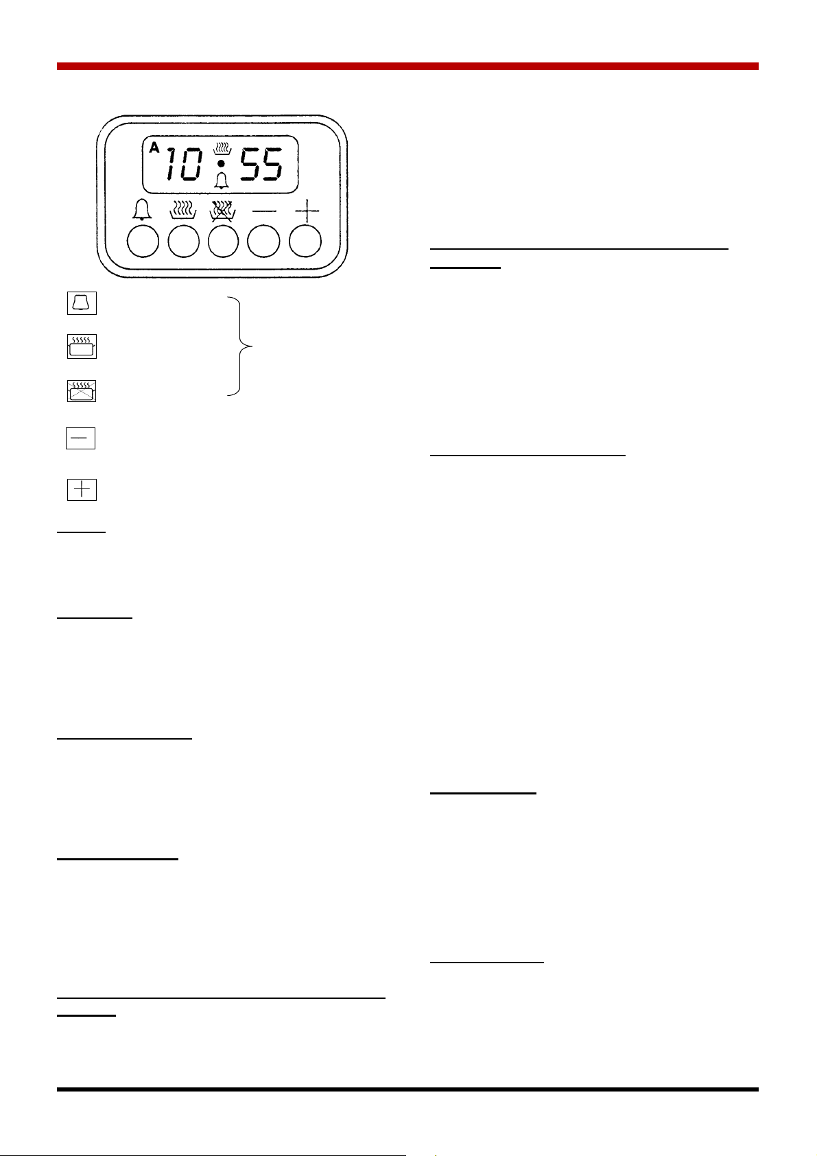
SWITCHING ON THE GRILL ELEMENT:
Press the corresponding switch marked with the
Grill symbol. This switches on the grill element, a
pilot light and the rotisserie motor.
The grill element can only be switched on with the
oven burner off. (A safety switch prevents the use
of the two different heat sources simultaneously).
CAUTION: When the grill is working the accessible
parts may become very hot. Keep children well
away.
CHANGING THE OVEN LAMP
-disconnect the appliance from the electrical
mains;
-unscrew the protective cap 0 which projects into
the oven;
-unscrew the lamp and replace it with another of
the same power and resistant to high tempera-
tures (300oC);
-replace the cap, fitting the notches in the tangs N,
and screw down (See Fig.17).
REMOVING THE OVEN DOOR
Open the oven door, on the hinge there is a hook,
rotate this hook towards the cooker as as much as
possible. Fig 18a shows the hook in the normal posi-
tion, Fig 18b shows the hook rotated for removing
the oven door. Partially close the door and pull
away from the cooker. To reassemble follow the
same procedure in the reverse order.
USING THE ROTISSERIE
Impale the food for cooking on the rotisserie spit,
taking care that it is secured between the two forks
(A and B), and balancing the weight to avoid forcing
the motor unnecessarily. (Fig.24)
HOBS (Gas burners and electric
hotplates)
To ignite the gas burners, follow the instructions
given in the HOB BURNERS section.
The electric hotplates are switched on by turning the
knob to the setting required. A diagram showing the
relations between the knobs and hotplates is screen
printed on the front panel beside each knob.
The hotplate switch has 5 positions:
- 0 - OFF position
- 1 - MINIMUM power setting
- 2 - MEDIUM-LOW power setting
- 3 - MEDIUM-HIGH power setting
- 4 - MAXIMUM power setting (Fig.25)
When switching on a hotplate for the first time, or if
it has been out of use for a long period, operate it
without a pan on setting 1 for 3 minutes to eliminate
any moisture absorbed by the insulation. To avoid
wasting energy, use flat bottomed pans and do not
use pans smaller in diameter than the hotplates.
(See Fig.26).

Setting
Select a function by pressing the function button and
set the required time with the +/- buttons.
+/- Buttons
Pressing the “+” button increases the time set,
pressing “-” decreases it. The count-up or count-
down speed increases the longer the button is held
in the appropriate position.
Setting Time of Day
Keep duration and end time buttons pressed while
setting time of day with +/- buttons. Any programme
which has been set is cancelled and the outputs
switched on.
Manual Operation
Press duration and endtime button together. The
relay contacts will switch on.
The “A” symbol will be erased, the pot symbol illumi-
nated.
Any programme which has been set is cancelled.
Semi-automatic Operation with Cooking
Duration
Select cooking duration function and set required
duration with the +/- button.
8
Minute Minder
Cooking Duration Function Buttons
Cooking end time
OPERATION OF MINIATURISED ELECTRONIC PROGRAMMER
"A" and cookpot symbols appear.
The relay output becomes active.
If time of day = cooking end time the relay out-
put and the cookpot symbol are switched off.
The audible signal sounds. The symbol "A"
blinks.
Semi-automatic Operation with Cooking
End Time
Select cooking end time function and set
required end time with the +/- button.
The "A" and cookpot symbols appear.
The relay output becomes active.
If time of day = cooking end time the relay out-
put and the cookpot symbol are switched off.
The audible signal sounds and "A" blinks.
Fully Automatic Operation
Select cooking duration function and set
required duration with the +/- button.
The "A" symbol appears. The relay is switched
on and the cookpot symbol appears.
Select cooking end time function and the earli-
est possible end time is displayed.
Set the required end time with the +/- button.
The relay and the cookpot symbol are
switched off.
The cookpot symbol appears again when time
of day = the calculated start time.
After the automatic programme has ended, the
symbol "A" blinks.
The audible signal is heard and the cookpot
symbol and the relay are switched off.
Minute Minder
Select minute minder button and set required
time with +/- button.
As the time set elapses the symbol bell symbol
is displayed.
After the time set has elapsed, the audible sig-
nal sounds.
Audible Signal
The audible signal (1 Hz interval) sounds at
the end of a minute minder cycle or of a cook-
ing programme for a period of 7 minute. The
signal can be cancelled by pressing any func-
tion button.

9
Pressing the "-" button without having previ-
ously selected a function the frequency of the
signal changes.
Aselection from 3 possibilities can be made.
The selected signal is audible as long as the
"-” button is pressed.
Programme Start and Verification
Aprogramme which has been set is carried
out after setting the time required.
The "time-to-run" can be verified at any time
by selecting the appropriate function.
Setting Error Identification
The setting is incorrect if time of day is in
between the calculated cooking start and end
times.
If an error has been made, this will be indicat-
ed by the audible signal and by the symbol "A"
flashing.
The faulty setting can be corrected by chang-
ing one or both functions.
Cancelling a Programme
Aprogramme can be cancelled by selecting
the manual function.
After a programme which has been set comes
to an end, it is automatically cancelled.

The electric oven is controlled by the switch com-
bined with the oven thermostat. As the knob is
turned clockwise, the following functions are
obtained in this order:
- Oven light switches on;
- 0...250- numerical indication of the temperature
which can be obtained in the oven (in this thermo-
stat-controlled function, the oven is heated by two
elements, one in the top and one in the bottom);
- top element only on;
- bottom element only on;
- grill element on. (See Fig.28)
The thermostat pilot light indicates the progress of
the thermostatically controlled cycles, switching on
and off accordingly.
USING THE ROTISSERIE:
The rotisserie is started by pressing the correspon-
ding switch. (See Fig.29).
10
ELECTRIC OVEN

11
- cakes (soft and thick)
- large quantities of foods
- cooking various dishes simultaneously
Characteristics of fan cooking:
- heat provided from all directions
- cooking possible on a number of shelves
- high moisture removal
- thawing is possible with or without heat emission.
CENTRAL GRILL
This cooking mode is used for small
amounts of food (low energy consumption)
DOUBLE GRILL
Used when the grill is required over a wide
area.
DOUBLE GRILL WITH FAN
Action of the fan combined with the power-
ful action of the two grill heating elements is
ideal for cooking large items.
BOTTOM ELEMENT WITH FAN
The heat from below is evenly distributed
over the oven, allowing slow, gentle
cooking.
CAUTION
THE OVEN DOOR MUST BE CLOSED
DURING COOKING IN ALL MODELS,
INCLUDING THOSE USING THE GRILL.
CAUTION
THE THERMOSTAT MUST ALWAYS BE
SET ON 250oC DURING COOKING
USING THE GRILL OR DOUBLE GRILL
WITH FAN.
COMMON PRECAUTIONS FOR GAS AND ELEC-
TRIC OVENS
- Before cooking, check that only the accessories
required are inside the oven.
-Before placing the food inside allow the oven to
preheat for about 15 minutes, turning the knob to
the temperature required.
-For excellent results, try to open the oven door as
little as possible.
-When grilling foods on a grating, always place
the fat collection tray on the runners immediately
below. (See Fig.30).
Thanks to the various heating elements controlled
by a switch and regulated by a thermostat, this oven
offers various cooking options:
- CONVENTIONAL STATIC
- FAN
- INFRARED (grill)
THERMOSTAT
allows the temperature of use to be
selected and set.
FUNCTION SELECTOR SWITCH
allows selection of the cooking mode.
SELECTOR SWITCH FUNCTIONS
OVEN LIGHT
The oven light and general pilot light come
on and will remain on as long as the oven
is in use.
DEFROSTING
The fan starts up but no heat is emitted.
This aids the thawing of foods, reducing
the time normally required by about 1/3.
STATIC OVEN
(conventional cooking)
The heat is provided from above and below.
The oven must be preheated before the foods are
placed inside. Static cooking provides optimum
results with:
- Cakes (dry and thin)
- pizzas
- bread
Characteristics of static cooking:
- heat provided from above and below
- cooking is possible on only one shelf
- low moisture removal.
FAN OVEN
The circular heating element and fan come
into operation and the heat is spread
evenly to all levels of use.
Various types of foods can be cooked on different
shelves, naturally with the appropriate cooking
times.
The oven must be preheated before the foods are
placed inside. Fan mode provides optimum results
with:
MULTIFUNCTION OVEN

NOTES:
The data given are guidelines.
Experience, eating habits and personal taste will suggest any variations required.
The times and temperatures indicated refer to average quantities of foods: 0.8/1.5kg).
On average, lower temperatures and shorter times are required when cooking using fan functions.
When cooking on more than one shelf at once (for multifunction ovens only) always place the containers in
the centre of the shelves.
COOKING GUIDELINES
COOKER TYPE
SINGLE OVEN DOUBLE OVEN
3
2
2
3
2
2
2
3
3
3
3
3
3
3
3
3
2
2
EFEF
TEMPERATURE
oC
TIME
(Minutes)
SHELF LEVEL SHELF LEVEL
SWEETS
Pastry
Sponge Cakes
Jam Tart
Fruit Cake
FISH
Fillets or slices
Roast
In foil
MEAT
Veal
Pork
Chicken
Turkey
Beef
Lamb
BREAD & PIZZA
Pizza
Muffins
Bread
BAKES
Vegetable Bake
Pasta Bake
2 (2/4)
2 (1/3)
2 (1/3)
2 (2/4)
2 (1/3)
2 (1/3)
2 (1/3)
2 (2/4)
2 (2/4)
2 (2/4)
2 (2/4)
3 (2/4)
2 (2/4)
2 (2/4)
2 (2/4)
3 (2/4)
2 (1/3)
2 (1/3)
4
3
3
4
3
3
3
4
4
4
4
4
4
4
4
4
3
3
2 (2/4)
2 (1/3)
2 (1/3)
2 (2/4)
2 (1/3)
1 (1/3)
2 (1/3)
2 (2/4)
2 (2/4)
2 (2/4)
2 (2/4)
2 (2/4)
2 (2/4)
2 (2/4)
2 (2/4)
2 (2/4)
2 (1/3)
2 (1/3)
180/200
190/210
190/210
180/200
160/180
180/200
190/210
180/200
180/200
190/210
190/210
200/220
200/220
190/210
180/200
210/230
170/190
180/200
30/40
30/40
30/40
30/40
20/30
25/35
25/35
60/70
60/70
80/90
80/90
70/80
80/90
20/30
20/30
30/40
30/40
30/40
FAN OVEN
ELECTRIC OVEN
CLEANING
Caution: before any cleaning or mainte-
nance work, always disconnect the power
supply to the appliance.
The burners and oven must be cleaned regularly to
avoid the build-up of grease which will produce
fumes, unpleasant smells and malfunctions over
time.
If parts are removed for cleaning, ensure that they
are carefully replaced.
Never use steel blades, powder detergents or abra-
sive sponges. Never use acid or chlorine based
products.
If no specific commercial products are available, use
soapy lukewarm water. All components washed
must be rinsed and dried thoroughly before use.
(Fig.31)
12

FIG.9
FIG.10
FIG.11
FIG.12
FIG.14
FIG.15
FIG.6
FIG.7
FIG.8
FIG.4
FIG.5
13
FIG.16
FIG.17
FIG.18
FIG.19
FIG.21
A
B
Hook in normal
position
Hook fully
rotated

FIG.25
FIG.30
FIG.26
FIG.28
FIG.24
14
FIG.31
FIG.32

15
We undertake to repair or replace, free of charge to you any part found to be faulty within the 2 year
period from the date of purchase provided that:-
*The fault is, in our opinion, caused by defective workmanship, or material and not by accident,
misuse, neglect or normal wear and tear.
*Any manufacturing defect is reported to the stockist from whom you bought the appliance within
2 years of the date of purchase.
*The Waterford appliance is installed to the Manufacturer’s recommendations and by a suitably
qualified person.
*The guarantee registration form is completed fully and returned to us within 30 days of the
purchase date.
IMPORTANT NOTICE: Any alteration to this appliance that is not approved in writing by Waterford Stanley
will render the guarantee void.
WARRANTY
Rev: 001 DP 040517
Waterford Stanley Ltd.,
Bilberry, Waterford, Ireland.
Tel: (051) 302300 Fax (051) 302375
This manual suits for next models
5
Table of contents