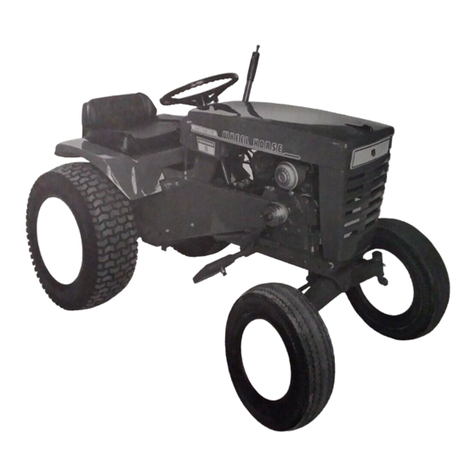
Wheel Horse RJ-58-59 User manual

I
I
I
I
I
I
I
I
I
I
I
I
I
I
I
I
I
I
I
I
I
I
I
I
WHEEL-HORSE
PRODUCTS
I
Copyright
1957
Wheel-Horse
Products,
Inc_
I
I
I
-
..
--
SOUTH
BEND,
INDIANA
www.MyWheelHorse.com

-
-,;'/
.
..../
---
----
--
,
am
speaking
directly
to
you
because
my
builders,
Wheel
Horse Products, Inc.,
felt
that
the
information
you'll
need
to
operate
and
maintain
me
should
come
straight
from
the
Wheel
Horse's
mouth.
(Their sense
of
humor
is
not
so hot,
but
they
sure
do
turn
out
a
mighty
fine
tractor
...
me,
that
is.)
Many
thanks
for
choosing me.
"m
flattered.
I assure
you
that
my
strength,
dependability
and
versatility
will
let
you
tackle
any
rough,
tough
job
around
your
grounds.
•
One
thing
we
"gotta"
get
settled
right
off
the
bat.
I
can't
feed
myself
so it's
up
to
you
to
supply
the
petroleum
products I require.
Actually,
I
need
very
little
attention,
and
if
you
provide
food,
shelter
and
doctor's care,
I'll
work
long
hours each
day
for
many
years
to
come.
A WHEEL-HORSE IS
BORN!
LEMME
OUT/
J
f:.
_ \)11
'-----...
-;f!l
::-----
•
...
To
protect
me
during
shipment,
I
arrived
at
your
dealer's
store
neat-
ly
and
completely
packed
into
one
sturdy
shipping
carton.
Your
dealer
has
probably
assembled
me
for
you.
If
not,
I
am
very
easy
to
set
up.
Following
is
a check list
of
my
parts
included
in
the
carton
unassembled
(to
make
a
smaller
and
more
compact
shipping
package),
which
must
be
installed
in
their
proper
places:
2 Rear Wheels
2 Front Wheels
I Muffler, Exhaust
I Exhaust Pipe
I Exhaust Pipe, 45°
elbow
I
lift
Hitch with pin
I Steering Wheel (under
the
seat)
2
3,4"
Snap
Ring (No. 1127)
I
1J4"
"U"
Bolt (No. 1240)
I
1J2
x 1
Carriage
Bolt
(No. 1106)
I
3/16
x
13/4
Roll
Pin (No. 1127)
I Clevis Pin (No. 1235)
6 Wheel Bolts (No. 1004)
Bolt
on
the
rear
wheels
with
my
tire
treads
pointing
forward
on
top,
my
rims
dished
out
and
my
valves
on
the
inside,
with
6
wheel
bolts
provided.
Arrows
on
the side
of
my
tires
point
the
proper
forward
direction
of
rotation.
Slip
on
my
two
front
wheels
and
secure
with
the
snap-rings
provided.
My
steering
wheel
has been
bolted
under
the
seat.
Remove
the
shipping
bolt
and
remove
the
steering
wheel.
Now
bolt
my
seat-gently
sir-to
the
seat
spring
with
the
carriage
bolt
provided,
in
either
the
forward
or
the
rear
hole
of
my
seat
spring,
depending
on
the
length
of
your
legs. Fasten
my
steering
wheel
to
the
steering
column
with
the
roll-pin
provided.
Install
my
draw
bar
hitch
behind
my
transmission
and
between
cover
plates
with
the
pin
provided.
(See
exploded
view.)
Connect
the
rear
end
of
my
lift
cable
to
my
draw
bar
hitch
with
the
clevis
pin
provided.
Screw
the
muffler
pipe
into
position
and
secure
with
the
V4"
"U"
bolt
provided.
(See
exploded
view.)
Screw
on
45
°
elbow
and
exhaust
muffler,
so
that
I can
blow
my
breath
(exhaust
gases)
out
from
under
my
hood,
45
°
from
straight
forward.
LET'S
GET
OILED!
Important:
There
is
no oil in
the
crank
case
of
my
engine
when
shipped
from
the
factory.
Before
starting
my
engine
be sure to
fill
my
crank
case
and
air-
cleaner
to
the
level
indicated
with
the
recommended
lubri-
cant, specified in
the
engine
manua
I.
Fur-
ther
instructions
per-
taining
to
my
engine,
its care
and
lubrica-
tion
are
contained
in
the
engine
manual.
SHOOT
THE
JU
ICE
TO
ME,
BRUCE!
You
had
better
read
these instructions
carefully,
Boss!
To insure a
longer
useful
life
for
me,
remember
that
I
require
the
same
type
of
proper
lubrication
as
the
family
automobile.
Refer
to
the
exploded
view
for
the
location
of
my
seven high-pressure grease
fittings,
and
www.MyWheelHorse.com

lubricate
each
grease
fitting
with
regular
pressure
gun
lubricant
approximately
every
eight
to
ten hours
of
operation.
Lubricate
all
the
rest
of
my
working
parts
periodically
with
light
oil
to
keep
my
joints
from
squeak-
ing.
You
don't
want
me
to
get
arthritis!
My
automotive-
type
sliding
gear
transmission,
reduction
gears
and
dif-
ferential
fit
compactly
into
one
oil-tight
case
and
all
of
my
gears
operate
in
an
oil
bath.
Oil
was
put
into
my
transmission
at
the
factory
before
it
was
tested
under
power
in
all
four
working
gears
and
this
oil
was
not
removed.
However,
do
not
attempt
to
operate
me
with-
out
at
least checking
the
oil
level in
my
transmission.
Loss
of
oil
might
occur
due
to
improper
handling
in
shipping.
Check
the
oil-level
in
my
transmission
by
removing
my
oil
check-plug,
located
on
the
right
side
of
the
transmission
just
below
the
axle,
making
sure
that
the
oil
is
up
to
this level.
If
necessary,
remove
filler
plug
(located on
top
of
the
transmission)
and
add
S.A.E.
No.
90
Gear
Lube. Check
oil
level
after
each
25
hours
of
operation.
My
belt-idler
is
a
grease
sealed
ball-bearing
and
requires
no
further
lubrication.
My
front
tires
have
been
filled
with
liquid
anti-freeze
ballast
at
the
factory
to
provide
additional
weight
in
my
front
end.
Do not check
the
pressure
of
my
front
wheels
as
the
ballast
contained
in
the
tires
is
harmful
to
the
ordinary
air-gauge,
and
some
ballast
will
be lost in
the
process.
My
rear
tires
should
be
inflated
to
six
to
eight
pounds
of
air-pressure.
My
rear
tires can
also
be
filled
with
a
liquid
ballast.
But this is
not
ordinarily
necessary as
the
weight
of
the
operator
adds
sufficient
weight
on
the
rear
tires
for
adequate
traction.
ALL
A
OA
D!
If
you
are
sure
my
engine
and
my
chassis
have
been
properly
serviced I
am
ready
to
go
to
work.
Refer
to
your
Engine Instruction
Manual
for
starting
and
running
my
engine.
Before
starting
my
engine,
make
sure
the
gear
shift
lever
is
in
the
neutral
position.
Flip
my
"On-
Off"
switch
to
the
"on"
position,
open
throttle
about
half-way
and
choke
if
the
engine
is cold
before
pulling
the
engine
over
with
my
retractable
starter.
To stop
the
engine,
simply
flip
my
"On-Off"
switch
to
the
"off"
position.
To
start
me
in
motion
depress
my
clutch
pedal
(located
on
the
left
side)
and
select
the
desired
speed
range,
(first,
second,
third
or
reverse)
by
manipulating
my
shift
stick
to
the
proper
position
as
shown
by
the
shift
instructions
printed
on
the
rear
of
the
hood.
My
gear
shift
lever
is
located
just
forward
of
my
seat. Do not
force
my
shift
lever
if
gears
do
not
immediately
mesh.
(Quickly
throw
clutch in
and
out,
then
shift
gears
again.)
Release
my
clutch
slowly
and
smoothly
to
avoid
jerky
starts. (I
don't
want
to
be
a
jerk!) Do
not
shift
my
gears
while
I
am
in
motion
without
depressing
my
clutch.
When
you
depress
my
clutch
pedal,
my
belt-idler
is
released
from
my
belt,
so
that
my
belt
cannot
drive.
When
my
clutch
pedal
is
released,
spring
LET'S
aO,JOE!
tension forces
my
belt
idler
down
on
my
belt
with
the
correct
amount
of
belt
tension
always
being
maintained.
I
am
unique
in
that
my
clutch
pedal
also
operates
my
brakes
when
it
is
depressed
all
the
way.
My
brake band,
located
on
the
left
side
of
my
transmission,
brakes
the
transmission,
which
in
turn
brakes
both
wheels.
Adjust
the
nuts
on
my
brake
rod
so
that,
when
you
depress
my
clutch
pedal,
my
brake
band
tightens
around
my
brake
drum,
just
before
my
idler
pulley
hits
the
top
of
my
belt
guard.
This
clutch-brake
pedal
combination
makes
it
very
simple
to
shift
gears
on
a
hillside
without
clashing
gears.
It
is
not
necessary
to
use
my
brakes
while
going
down
a
hill,
unless
you
wish
to
come
to
a
complete
stop,
because
my
gear
train
will
hold
me
back
and
keep me
from
running
away
down
the
hill.
When
leaving
me
parked
on
unlevel
ground,
leave
my
gear
shift
lever
in
the
low-gear
position.
This
will
act
as
an
emergency
brake
to
keep
me
from
rolling
away.
Give
me
the
same care
that
you
give
your
automobile
and
please,
don't
abuse
me
by
improper
handling.
Keep
me
sheltered
from
the
weather
when
not
in
use,
and
it's a
good
idea
to
visit
your
Wheel
Horse
dealer
from
time
to
time,
and
have
him
give
me a
thorough
checkup
for
longer
tractor
life
and
better
performance.
Sincerely yours,
YOUR WHE.EL-HORSE
DEALER
WILL
\(E~P
ME
IN
lOP
SHAPE!
+
www.MyWheelHorse.com

[~
~-
67
a 0 0 0 0
Cl
00 0
a 0
(
0'\
0 0
\00
~
I \
www.MyWheelHorse.com

Ref.
Port
No.
No.
1
3504
2
3509
3
3546
4
3579
5
3567
6
3552
7
3556
8
3410
3435
9
10 3401
11
3400
12
3456
13
3560
14
3538
15
3514
16
3577
17
3559
18
1146
19
3572
20
1782
21
1712
22
1656
23
1657
24
1514
1521
1709
25
1781
26
1779
27
1790
28
1158
3487
29
1159
3488
30
1160
3489
3490
31
1785
32
1789
33
1786
34
1192
35
1787
36
3467
37
3501
38
3503
39
3515
40
3516
41
3517
42
3518
43
3573
44
3519
45
3520
46
3521
47
3522
48
3523
49
3524
50
3525
51
3526
52
3527
53
3528
54
1813
55
3530
56
3531
57
3502
58
3533
59
3575
60
3532
61
3535
62
1611
63
3513
64
3550
65
3549
66
3438
67
3409
68
1014
69
3539
70
1000
p
No.
Description Req.
Right Transmission
Cover
..............
1
left
Transmission
Cover
...............
1
Frame
•..•..............•...•••••••..
1
Belt
Guard,
Attachment
...............
1
Clutch
Pedal
.........................
1
Idler Arm
........•..................
1
Clutch Arm
.......•.......•
•
..........
1
Tool
lift
lever
........................
1
Front
End
............................
1
Front
Spindle,
(Right)
..................
1
Front
Spindle,
(left)
...................
1
Tie Rod
.............................
1
Hitch,
Draw
Bar
......................
1
lever,
Shift
..........................
1
Collar, Shift
lever
....................
1
Boot, Shift
lever
.....................
1
Brake
Shaft
and
Gear
................
1
Wire, Remote
Stop
....................
1
Pin,
Draw
Bar Hitch
..................
1
Throttle Control Assembly
..............
1
Wheel,
Front
.........................
2
Tire, Front,
4:00
x 8
..................
2
Tube, Frant,
4:00
x 8
..................
2
Ball
Bearing
.................•........
4
Sintered
Iran
Bearing
.................
4
Front Tire
and
Wheel
Assembly
.........
2
Engine,
Clinton
.......................
1
Engine,
Kohler
........................
1
Fuel
line
............................
1
Nipple, Pipe, '/2 x
31f2
(Clinton only)
....
1
Nipple, Pipe,
3.4
Close (Kohler)
...
:.....
1
Nipple, Pipe, '/2 x 11'/2 (Clinton only)
...
1
Nipple, Pipe,
3.4
x 14'/2 (Kahler only)
....
1
45° Elbow x '/2 (Clinton only)
..........
2
90°
Elbow x
3.4
(Kohler only)
..........
1
45°
Elbow x
3.4
(Kohler only)
..........
1
Fuel Tank
with
cap
...................
1
Cap,
Fuel
Tank
.......................
1
Strainer
..............................
,1
Nipple, Close
........................
1
Connector,
Straight
Gas
line
...........
1
lock
Bar,
lift
lever
...................
1
Transmission Housing
..................
1
Shift
Fork
......................•.....
2
Shift Rail, Front
......................
1
Shift Rail,
Rear
......................
1
Ball,
Stop
.........•..................
2
Spring,
Shift
Stop
.....................
1
Pin,
Shift
Stop
..•.....................
1
Rev.
Idler
Pin
....................•.•.
1
Rev. Idler
Gear,
with
Bearing
..........
1
Spline
Shaft
.........................
1
Input
Gear
.......................•..
1
Hi
and
Second
Gear
...................
1
low
and
Reverse
Gear
................
1
Cluster
Gear
................•........
1
Splined
Pinion
..............••.•......
1
Cluster
Shaft
Reduction
Gear
...........
1
Cluster
Shaft
Reduction Pinion
..........
1
Tool Pin
........
"., . . . . . . . . . . . . . . . . . . . 1
Axle
Gear,
Differential
................
2
Spider
Gear,
Differential
.............•.
4
Differential
Case
and
Gear
............
1
Cluster
Shaft
.........................
1
Spacer,
Belt
Guard
...................
2
Axle
................................
2
Differential Pins
......................
4
Pulley, Transmission
...................
1
Wheel
Hub
...................••......
2
Clutcn
Rod
...........................
1
Belt
Guard,
Transmission
...............
1
Steering
Rod
..............•...•......
1
Steering
lug
•..........•.•...........
1
Tension
Spring
......•..•.............
1
lift
Coble
...........................
1
Rubber
Grip
..........••............•
1
RT
Price
List
$
8.40
8.40
17.24
.60
1.80
.92
.80
3.60
4.32
2.80
2.80
1.48
3.00
1.68
.60
.52
14.40
.40
.60
1.90
4.50
12.00
3.40
.85
.85
18.00
108.00
108.00
.90
.20
.20
.64
.80
.35
.35
.35
4.72
.40
1.44
.16
.12
.24
16.40
2.80
.76
.76
.04
.04
.08
.40
3.20
1.00
6.00
3.40
3.68
14.00
2.16
4.32
2.60
.32
3.80
1.80
14.50
.92
.20
1.80
.40
2.00
3.00
.88
2.05
1.96
.85
.40
2.50
.40
LI
T
Ref.
Pari
No. No.
71
3468
72
3578
73
1035-l
74
1085
75
1001
76
3415
77
3461
78 3441
79
2510
80
3537
80-A
3583
81
1650
82
1654
83
1700
84
1608
85
1567
86
3279
87
1869
88
3540
89
3543
90
3545
91
3536
92
1516
93 1504
94
1517
95
1503
96
1502
97
1519
98
1518
99
3542
100 1228
101 3541
102
1234
103
1232
104
3582
105
1237
106
1238
107
1092
108 1062
109 1028
110
1064
111 1003
112 1143
1131106
114
1042
115
1161
116
1239
117
1108
118
1013
119
1004
120
1150
121
1016
122
1010
123 1113
124
1045
125
1039
126
1067
127 1034
128 1119
129
1240
1301120
131 1122
132 1008
133 1002
134 1244
135 1242
136
1133
137
1134
138
1227
139 1081
140
1243
141 1235
142
1127
143
1030
No.
Description Req.
Plunger
Rod
..........................
1
Guide,
Plunger
.......................
1
Torsion
Spring
......................•.
1
Shaft
Collar
...........•......•......
2
Knob
................................
1
Steering
Wheel
.......................
1
Clevis Pin,
Steering
....................
2
Steering
link
.................
•
.......
1
Seat
. . . . . . . . . . . . . . . . . . . . . . . . . . . . . . . . 1
Seat
Spring
..........................
1
lug,
Coble-Clamping
..................
1
Tire
with
Tube, 6 x 12
................
2
Tube,
Inner
..........................
2
Rim
...
. .
...
.........................
2
Pulley, Engine
........................
2
Belt (Special Oil Proof) 29A
............
1
Stop
Switch
..........................
1
Hood
with
Strops
..............•......
1
Brake
Drum
.........•................
1
Brake
Band
with
liner
................
1
Brake
Rod
...........................
1
Gasket,
Transmission
..................
2
Bronze
Bearing,
'l2x%xl'/a
............
1
Bronze Bearing,
3.4x
7
/ax
3
.4
..............
2
Bronze Bearing, J3/ax11/2x1-7
/16
........
2
Bronze
Bearing,
1xl1/ax
1112
............
2
Ball Bearing,
3.4
x1
o/ax3fa
................
3
Ball
Bearing
(Ground),
~xl
¥ax5/16
.....
4
Needle
Bearing
..................•....
1
Idler Pulley
..........................
1
Cromcal
"Wheel
Horse"
...............
2
Cromcal
"Shift
Instructions"
............
1
Oil
Seal
.............................
2
Oil
Seal
(Axle)
.......................
2
Spring
Anchor
........................
1
Cap
Screw,
Hex
Head,
1/4-20xo/a
........
2
Cop
Screw,
Hex
Head,
5/16-18x¥a
......
19
Cap
Screw, Hex
Head,
5/16xI8xl~
.....
2
Cop
Screw,
Hex
Head,
3/a-16x1
.........
7
Cap
Screw,
Hex
Head,
3/
a-16x
11/4
........
6
Cap
Screw
, Hex
Head,
3/a·16x1'/2
........
1
Stove
Bolt,
Slotted,
R.D.,
3/16xl
........
2
Stove
Bolt,
Slotted,
R.D., 1/4x¥a
.........
5
Carriage
Bolt, '12·13x1
.................
1
Set
Screw,
Socket Hd.
Cup
Point,
5/16-18x5/16
......................
2
Set
Screw,
Cup
Point, 3/
a
·16x¥a
.........
2
Set
Screw,
Full Dog Point, 1/4-20x3.4
.....
1
Pipe
Plug,
Va'l
................•.......
1
Pipe Plug,
114"
........................
1
Wheel Bolts,
Toper
Head,
7/16-20x
3.4
....
6
Sheet
Metal
Screw,
No. 7x1/2
...
_.
. . . .
..
2
Nut, Hex, NC,
3A1-16
......•...•.....•.
14
Nut, Hex,
Castle
NF,
~-16
.............
1
lockwasher,
Spring,
114"
...............
9
lockwasher,
Spring,
5/16"
.............
2
l k h S·
31.
" 12
oc
was
er,
pring,
,a
..............
.
lockwasher,
External
Shakeproof,
'/4"
...
5
Nut,
Hex,
1/4-20
......................
3
Flat
Washer,
SAE, 1/4"
.................
1
U Bolt
with
nuts,
lf4xl-l/16xJ3.4
........
1
Key,
Square,
3/16
Sq. x 2
.............
1
Key,
Woodruff,
No.9.................
4
Key,
Woodruff,
No. 15
................
4
Cotter
Pin,
Vex
1
..................•...
Roll Pin,
1/ax
1
.......................
.
Roll Pin,
5/32xI3/16
.................
.
Roll Pin,
3/16xl
.....................
.
Roll Pin, 3/ 16xl1/4
...................
.
Roll Pin,
3/
16x
13/4
...................
.
Roll Pin,
lf4xl'l2
.....................
.
CUPI
Plug,
5/16"
.....................
.
Yoke Pin,
lf4x51/64"
.................
.
S R·
31."
nap
lng,
14
......•.••••.......••..
Grease
Fitting, 1/4-28
.................
.
8
3
1
6
1
3
2
1
2
7
5
Price
List
.60
.10
.12
.60
.32
8.00
.50
.65
3.84
3.24
.20
22.50
4.85
7.00
1.52
2.16
1.12
11.00
2.60
2.20
.40
.20
.40
.46
.88
.68
.92
2.28
1.16
2.88
N/C
.20
.36
.32
.20
.05
.05
.10
.10
.10
.10
.05
.08
.20
.16
.16
.16
.10
.10
.12
.05
.05
.25
.05
.05
.05
.05
.05
.05
.20
.10
.10
.10
.05
.10
.10
.10
.10
.10
.10
.05
.10
.10
.10
www.MyWheelHorse.com

CHOOSE
FROM
22
optional
attachments
...
•
,.-.--
...:
.
.i't-.:-~""'-
-
With
a
Wheel-
Horse
yard
and
garden
tractor
Fun-work
with
Wheel-Horse
the
year
'round_.
_
mowing
lawn,
plowing
snow,
hauling
fill
or
compost.
Only
Wheel-
Horse
has
automotive
gearing,
steering
and
2-wheel
brakes.
Power
and
traction
to
spare
even
on
sloping
ground.
WHEEL-
ORSE
PRODUCTS
SOUTH BEND,
INDIANA
litho
in
U.S.A.
www.MyWheelHorse.com
Table of contents
Other Wheel Horse Lawn Mower manuals

Wheel Horse
Wheel Horse 5-1421 User manual

Wheel Horse
Wheel Horse 1-7231 User manual

Wheel Horse
Wheel Horse Commando 8 User manual

Wheel Horse
Wheel Horse 1057 Operation manual

Wheel Horse
Wheel Horse 1-2631 User manual

Wheel Horse
Wheel Horse A-65 User manual

Wheel Horse
Wheel Horse RJ-58-59 User manual

Wheel Horse
Wheel Horse Ranger 33R Service manual

Wheel Horse
Wheel Horse REO Royale IV LL-217 User manual

Wheel Horse
Wheel Horse Work Horse LT series User manual