Whirlpool ImPress LFB2611L User manual

CONSUMER SERVICES TECHNICAL
EDUCATION GROUP PRESENTS
L-73
JOB AID
Part No. 8178203
Model LFB2611L
ImPress
IRONING STATION
All manuals and user guides at all-guides.com
all-guides.com

WHIRLPOOL CORPORATION assumes no responsibility for any repairs made
on our products by anyone other than Authorized ervice Technicians.
FORWARD
This Whirlpool Job Aid, “ImPress Ironing tation,” (Part No. 8178203), provides the technician
with information on the installation, operation, and service of the ImPress Ironing tation. It is
to be used as a training Job Aid and ervice Manual.
The Wiring Diagram used in this Job Aid is typical and should be used for training purposes only.
Always use the Wiring Diagram supplied with the product when servicing the unit.
GOALS AND OBJECTIVES
The goal of this Job Aid is to provide detailed information that will enable the service technician to
properly diagnose malfunctions and repair the Whirlpool ImPress Ironing tation.
The objectives of this Job Aid are to:
• Understand and follow proper safety precautions.
• uccessfully troubleshoot and diagnose malfunctions.
• uccessfully perform necessary repairs.
• uccessfully return the Ironing tation to its proper operational status.
Copyright © 2002, Whirlpool Corporation, Benton Harbor, MI 49022
- -
All manuals and user guides at all-guides.com

TABLE OF CONTENTS
GENERAL............................................................................................................................... 1-1
afety First......................................................................................................................... 1-1
Model & erial Number Designations ................................................................................ 1-2
Model & erial Number Label And Wiring Diagram Locations .......................................... 1-3
pecifications..................................................................................................................... 1-4
Whirlpool ImPress Ironing tation Warranty ...................................................................... 1-5
INSTALLATION INFORMATION ........................................................................................... 2-1
urface Mounting............................................................................................................... 2-1
PRODUCT OPERATION ........................................................................................................ 3-1
Adjusting The Board Height ............................................................................................... 3-1
Adjusting The wivel Tension............................................................................................ 3-1
The Work Light .................................................................................................................. 3-1
Using The Iron ................................................................................................................... 3-2
toring The Ironing Board.................................................................................................. 3-2
COMPONENT ACCESS ......................................................................................................... 4-1
Removing The Light ocket, Indicator Light, Timer,
AC Receptacle, & Cutoff witch ..................................................................................... 4-1
COMPONENT TESTING ........................................................................................................ 5-1
Timer.................................................................................................................................. 5-1
Cutoff witch...................................................................................................................... 5-2
WIRING DIAGRAM................................................................................................................. 6-1
Page
- -
All manuals and user guides at all-guides.com

- v -
— NOTES —
All manuals and user guides at all-guides.com

Electr cal Shock Hazard
Plug nto a grounded 3-prong outlet.
Do not remove ground prong.
Do not use an adapter.
Do not use an extens on cord.
Fa lure to follow these nstruct ons can
result n death, f re, or electr cal shock.
Electr cal Shock Hazard
D sconnect power before serv c ng.
Replace all parts and panels before
operat ng.
Fa lure to do so can result n death or
electr cal shock.
GENERAL
SAFETY FIRST
Your safety and the safety of others s very mportant.
We have provided many important safety messages in this Job Aid and on the appliance. Always
read and obey all safety messages.
This is the safety alert symbol.
This symbol alerts you to hazards that can kill or hurt you and others.
All safety messages will follow the safety alert symbol and either the word
“DANGER” or “WARNING.” These words mean:
DANGER
WARNING
All safety messages will tell you what the potential hazard is, tell you how to reduce the chance
of injury, and tell you what can happen if the instructions are not followed.
You can be k lled or ser ously njured f you don’t
mmed ately follow nstruct ons.
You can be k lled or ser ously njured f you don’t
follow nstruct ons.
ELECTRICAL POWER SUPPLY &
GROUNDING REQUIREMENTS
WARNING
WARNING
1-1
All manuals and user guides at all-guides.com

MODEL & SERIAL NUMBER DESIGNATIONS
MODEL NUMBER
SERIAL NUMBER
1-2
MODEL NUMBER L F B 26 1 1 L Q 0
INTERNATIONAL ALE IND.
OR MARKETING CHANNEL
IF PRE ENT
PRODUCT GROUP:
L = DOME TIC LAUNDRY
PRODUCT IDENTIFICATION:
F = FINI HING PRODUCT
FEATURE CODE 1:
B = BUILT-IN BOARD ONLY
FEATURE CODE 2:
FIRST DIGIT
2 = 1 TO 6 BOARD HEIGHT PO ITION
SECOND DIGIT
6 = 1 TO 6 WIVELING BOARD PO ITION
FEATURE CODE 3:
1 = LIGHT, HUTOFF TIMER
FEATURE CODE 4:
1 = 42″ BOARD LENGTH
YEAR OF INTRODUCTION:
L = 2002, M = 2003
COLOR CODE:
Q = WHITE-ON-WHITE
T = BI CUIT-ON-BI CUIT
ENGINEERING CHANGE (NUMERIC)
SERIAL NUMBER M B M 04 54321
DIVISION RESPONSIBILITY
M = MARION, OH
MANUFACTURING SOURCE
B = IRON-A-WAY, INC.
YEAR OF PRODUCTION:
M = 2002
WEEK OF PRODUCTION:
04 = 4th WEEK
PRODUCT SEQUENCE NUMBER
All manuals and user guides at all-guides.com
all-guides.com

MODEL & SERIAL NUMBER LABEL
AND WIRING DIAGRAM LOCATIONS
1-3
Model/ erial Number Label
Wiring Diagram (Located
Behind Panel)
All manuals and user guides at all-guides.com

SPECIFICATIONS
1-4
Model No. LFB2611LQ & T
Color Q = White, T = Biscuit
Ironing Board Dimensions:
Height 47-1/8″
Width 14-1/4″
General:
Electrical Rating 15 Amps Max Current Draw
Electrical Outlets One, 3-Prong, Grounded
Maximum Iron Rating 1400 Watts
Built-in Work Light One
Timer Shutoff, Settable Up To 60 Minutes,
With Indicator Li
g
ht When On
Ironing Board Swivel
Capacity
360°. Board Locks In 4 Positions
(
12:00, 1:30, 3:00, 4:30
)
Ironing Board Height Adjustable, 2 Positions (4 Inch Difference)
Board Dimensions 42″
All manuals and user guides at all-guides.com

WHIRLPOOL ImPress IRONING STATION WARRANTY
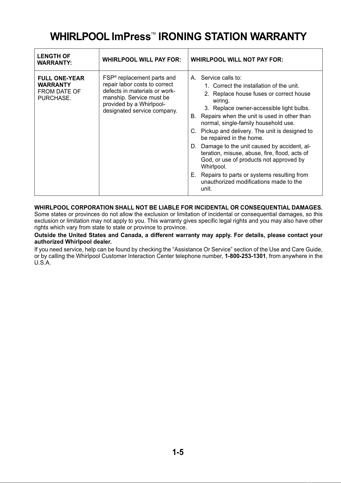
FULL ONE-YEAR
WARRANTY
FROM DATE OF
PURCHA E.
LENGTH OF
WARRANTY:
WHIRLPOOL CORPORATION SHALL NOT BE LIABLE FOR INCIDENTAL OR CONSEQUENTIAL DAMAGES.
ome states or provinces do not allow the exclusion or limitation of incidental or consequential damages, so this
exclusion or limitation may not apply to you. This warranty gives specific legal rights and you may also have other
rights which vary from state to state or province to province.
Outs de the Un ted States and Canada, a d fferent warranty may apply. For deta ls, please contact your
author zed Wh rlpool dealer.
If you need service, help can be found by checking the “Assistance Or ervice” section of the Use and Care Guide,
or by calling the Whirlpool Customer Interaction Center telephone number, 1-800-253-1301, from anywhere in the
U. .A.
WHIRLPOOL WILL NOT PAY FOR:
A. ervice calls to:
1. Correct the installation of the unit.
2. Replace house fuses or correct house
wiring.
3. Replace owner-accessible light bulbs.
B. Repairs when the unit is used in other than
normal, single-family household use.
C. Pickup and delivery. The unit is designed to
be repaired in the home.
D. Damage to the unit caused by accident, al-
teration, misuse, abuse, fire, flood, acts of
God, or use of products not approved by
Whirlpool.
E. Repairs to parts or systems resulting from
unauthorized modifications made to the
unit.
WHIRLPOOL WILL PAY FOR:
F P® replacement parts and
repair labor costs to correct
defects in materials or work-
manship. ervice must be
provided by a Whirlpool-
designated service company.
1-5
All manuals and user guides at all-guides.com

1-6
— NOTES —
All manuals and user guides at all-guides.com

1. Determine desired ironing board height
above the floor (see the Mounting Height
Chart below). NOTE: The ironing station
enclosure will extend approximately 11″
into the room.
NOTE: The user can adjust height of board
after the installation with a 4″ differential be-
tween a maximum and minimum height. Fig-
ures under the left column are for the normal
default position.
2. Locate the wall stud that will be used for
mounting the ironing station. The stud
should be located as close to the center of
the cabinet as possible.
3. Using a 3/16″ drill bit, predrill holes in the
upper and lower cabinet cross braces
where the lag screws will be located.
4. If installed, allow at least 16″ to the side of
the cabinet for the door swing.
5. Using a 3/16″ drill bit, predrill a pilot hole in
the wall stud where the cabinet will be
attached to the wall.
6. Attach the cabinet to the wall by inserting
the lag screws, (included with the ironing
station), through the predrilled holes in the
cabinet cross frames, or braces, and screw
them into the predrilled pilot holes in the
wall stud.
ELECTRICAL CONSIDERATIONS
All electrical work must be done in accordance
with all applicable electrical codes.
WARNING: Turn off the power at the serv ce
entrance before w r ng th s un t.
Pigtails are provided behind the control panel.
Use the strain relief provided.
4
3
1
INSTALLATION INFORMATION
SURFACE MOUNTING
Desired Board Height Mount Cabinet Above Floor
(Inches) (Inches)
38 30
37 29
36 28
35 27
34 26
33 25
32 2 4
31 2 3
30 22
29 21
28 20
2-1
Access Hole
All manuals and user guides at all-guides.com
all-guides.com

2-2
— NOTES —
All manuals and user guides at all-guides.com

PRODUCT OPERATION
ADJUSTING THE BOARD HEIGHT
1. Pull the top of the board forward several
inches.
2. To raise the board:
a) Grasp the top of the board frame, pull
the board forward an inch or so, and
lift the frame slightly to unlock the posi-
tioning rod.
b) Push the positioning rod in and slide it
to the back of the slots in the side brack-
ets.
c) Lift the positioning rod to the upper slot
position, then pull the rod forward as
far as the slot allows.
3. Rotate the front of the board down to its
ironing position.
ADJUSTING THE SWIVEL TENSION
The ironing board can be rotated 360° by
moving the front to the left or right. The tension
knob under the board may have to be loosened
to obtain a comfortable swivel tension. To
adjust the tension, turn the knob clockwise
(tighten), or counterclockwise (loosen).
Upper
Position
THE WORK LIGHT
A work light is activated when the ironing
board is placed in a horizontal position and
the timer is turned on.
Tension Knob
Lower
Position
3-1
Positioning Rod
Board Frame
Lift Frame
Pull Board
Out 1 to 2″
Work
Light
All manuals and user guides at all-guides.com

USING THE IRON
1. Lower the board to the ironing position.
2. Plug the iron cord into the grounded re-
ceptacle.
3. Rotate the timer knob clockwise to turn the
power to the iron on, and set the timer for
an approximate work time (5 to 50 min-
utes).
4. When ironing is completed, turn the timer
knob to the “0” position.
5. Place the iron in the hot iron storage
compartment in its upright position with
the bottom facing the metal heat shield.
STORING THE IRONING BOARD
1. If you swiveled the ironing board, return
it to the straight position.
2. Lift the front of the ironing board and return
it to the upright position.
NOTE: When moving the ironing board to the
upright position, the board will depress the
electrical circuit cutoff switch. At that time, the
indicator light and work light will go out, and
power to the AC receptacle will be shut off.
3-2
Timer
Ironing Board
Cutoff witch
AC Receptacle
All manuals and user guides at all-guides.com

COMPONENT ACCESS
REMOVING THE LIGHT SOCKET, INDICATOR LIGHT,
TIMER, AC RECEPTACLE, & CUTOFF SWITCH
Electr cal Shock Hazard
D sconnect power before serv c ng.
Replace all parts and panels before
operat ng.
Fa lure to do so can result n death or
electr cal shock.
WARNING
NOTE: harp edges may be present.
1. Disconnect the power to the ironing sta-
tion.
NOTE: The location of the components that are
serviced in this section are shown below:
Indicator Light
Timer
AC Receptacle
Cutoff witch
2. Lift and remove the iron storage wedge
from the unit.
Mounting crew
(1 of 3)
Component Cover
4-1
Cont nued on the next page.
Protective
Cover
Light Lens &
Light ocket
3. Lower the ironing board.
4. Place a towel or something similar on top
of the ironing board to protect it.
5. Remove the three mounting screws from
the component cover and remove the
cover from the bracket. Lay the compo-
nent cover on the protective ironing board
cover as shown below.
Iron torage Wedge
Iron torage Wedge
Component Cover
All manuals and user guides at all-guides.com

7. To remove the nd cator l ght:
a) Cut the two indicator wires near the
case, as shown.
4-2
b) Remove the nut from the light socket
and remove the socket from the mount-
ing hole.
6. To remove the l ght socket:
a) Remove the two screws from the light
lens and remove the lens, then remove
the light bulb from the socket. NOTE:
When you reinstall the light lens do not
overtighten the two screws.
Light Lens
crew crew
c) Cut the socket wires at the two loca-
tions shown below.
d) Remove 1/2″ of insulation from the cut
wire ends, and splice the light socket
wires to the wiring harness using two
twist-on wire nuts. Trim the wire
lengths, as necessary.
e) Wrap electrical tape around the wires
to hold them together.
Cut Here
Cut Here
Light ocket
Light
ocket
Nut
Twist-On
Wire Nut
Electrical
Tape
Cut 2 Indicator Wires Here
All manuals and user guides at all-guides.com
all-guides.com

Locking Arm
Timer Knob Timer crews
d) Cut the timer motor wire going to the
crimp-on connector at the indicated lo-
cation shown above.
e) plice the timer motor wire to the wir-
ing harness using a twist-on wire nut
(see steps 6d and 6e on the previous
page for the procedure).
Indicator
Light
4-3
b) Press in on the locking arms, and push
the indicator light out of the component
cover.
c) plice the indicator light wires to the
wiring harness using two twist-on wire
nuts (see steps 6d and 6e on the pre-
vious page for the procedure).
8. To remove the t mer:
a) Pull the knob off the timer shaft.
b) Remove the two screws and remove
the timer from the component cover.
c) Disconnect the three wires from the
timer terminals. The wires are con-
nected as follows:
Terminal 1 = cutoff switch wire
Terminal 2 = timer motor wire
Terminal 3 = AC (Black) wire
Timer
Cut Motor Wire Here
Terminals 1 2 3
Cont nued on the next page.
All manuals and user guides at all-guides.com

4-4
Electr cal Shock Hazard
Connect green ground w re to ground
screw.
Fa lure to do so can result n death or
electr cal shock.
WARNING
10. To remove the cutoff sw tch:
a) Remove the two wire connectors from
the switch terminals.
b) Push in on the two locking arms and
push the switch out of the cutout.
IMPORTANT REASSEMBLY NOTE: Be sure
to reconnect the green ground wire from the
AC receptacle to the component cover bracket.
Locking
Arm
Cutoff witch
9. To remove the AC receptacle:
a) Cut the black and white receptacle
wires at the indicated locations shown
below.
b) Press in on the locking spring, and push
the receptacle out of the component
cover.
c) Remove the screw from the eyelet at
the end of the green ground wire and
remove the wire from the component
cover bracket.
AC Receptacle
Locking pring
Cut Receptacle
Wires Here
d) plice the AC receptacle wires to the
wiring harness using two twist-on wire
nuts (see steps 6d and 6e on page 4-2
for the procedure).
Green Ground Wire
2 Wire Connectors
All manuals and user guides at all-guides.com

Before testing any of the components, perform
the following checks:
• The most common cause for control failure is
corrosion on connectors. Therefore, discon-
necting and reconnecting wires will be nec-
essary throughout test procedures.
• All tests/checks should be made with a VOM
or DVM having a sensitivity of 20,000 ohms-
per-volt DC, or greater.
COMPONENT TESTING
• Check all connections before replacing com-
ponents, looking for broken or loose wires,
failed terminals, or wires not pressed into
connectors far enough.
• Resistance checks must be made with power
cord unplugged from outlet, and with wiring
harness or connectors disconnected.
Refer to page 4-1 for the procedure for servic-
ing the timer.
1. Disconnect the power to the ironing sta-
tion.
2. Disconnect the timer motor connector from
terminal 2 of the timer.
TIMER
Motor
Wires
Terminals
3. et the ohmmeter to the R x 1K scale.
4. Touch one ohmmeter lead to the timer
motor wire terminal, and the other lead to
one of the white AC wires. The meter
should indicate between 2000 and 2400 Ω.
5. et the ohmmeter to the R x 1 scale.
6. et the timer to 0 (off).
7. Touch the ohmmeter leads to timer termi-
nals 1 and 3. The meter should indicate an
open (infinite) circuit.
8. Turn the timer knob to the 1 position.
9. Touch the ohmmeter leads to timer termi-
nals 1 and 3. The meter should indicate a
closed (0 Ω) circuit.
5-1
WARNING
Electr cal Shock Hazard
D sconnect power before serv c ng.
Replace all parts and panels before operat ng.
Fa lure to do so can result n death or electr cal shock.
All manuals and user guides at all-guides.com

CUTOFF SWITCH (N.C.)
WARNING
Electr cal Shock Hazard
D sconnect power before serv c ng.
Replace all parts and panels before operat ng.
Fa lure to do so can result n death or electr cal shock.
1. Disconnect the power to the ironing sta-
tion.
2. Disconnect one of the wires from the cutoff
switch terminals.
3. et the ohmmeter to the R x 1 scale.
4. Touch the ohmmeter leads to the N.C.
(normally-closed) and COM (common) ter-
minals. The meter should indicate a closed
(0 Ω) circuit.
5. With the meter connected to the switch
terminals, press in on the switch button.
The meter should indicate an open (infi-
nite) circuit.
5-2
Refer to page 4-1 for the procedure for servic-
ing the cutoff switch.
All manuals and user guides at all-guides.com
Other manuals for ImPress LFB2611L
1
Table of contents
Other Whirlpool Ironing Center manuals