Instruction Manual / DE0, DE1 and DE2
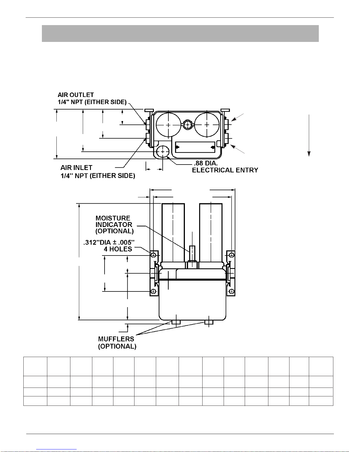
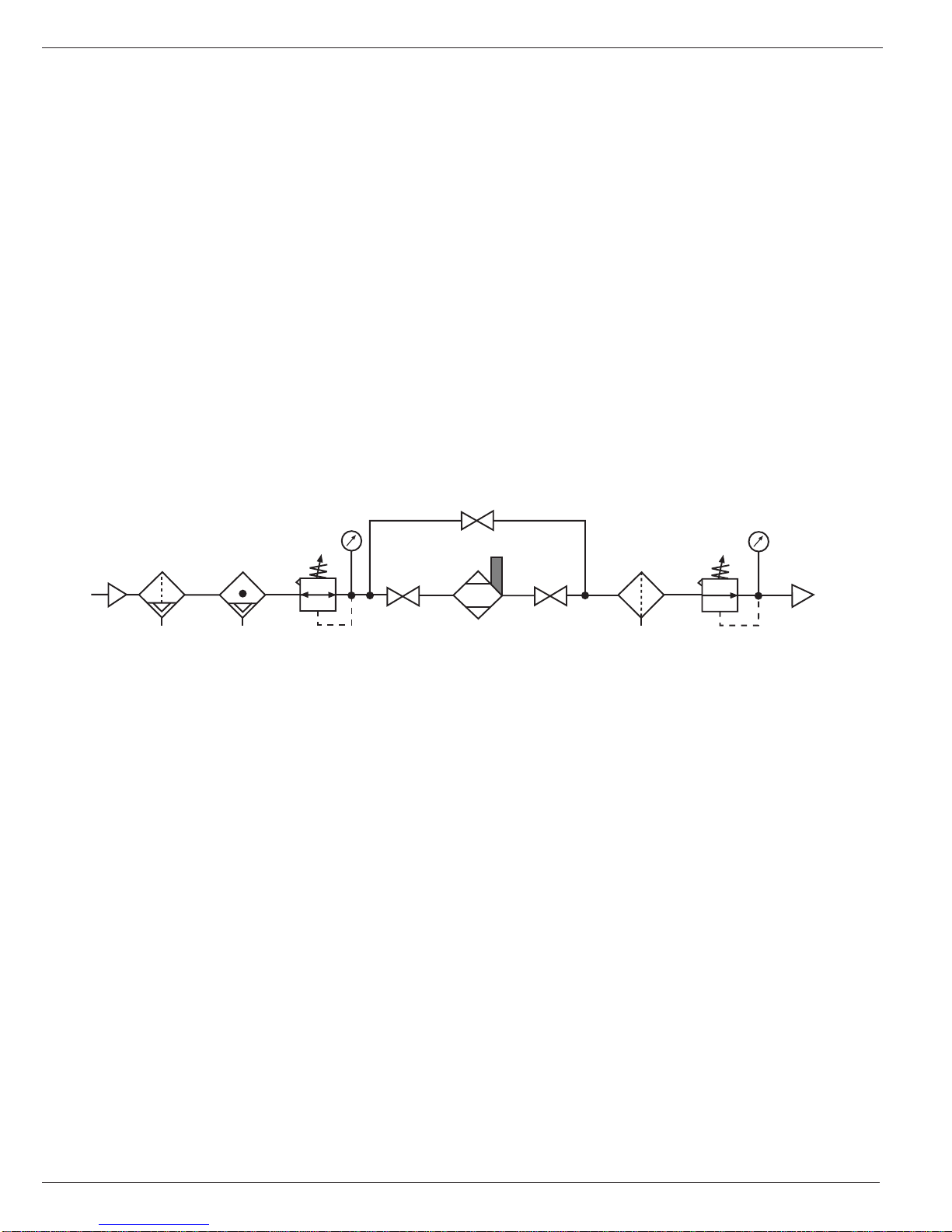
Wilkerson Compact Heatless Air Dryers
PARTS DESCRIPTION – WILKERSON HEATLESS DRYERS
ITEM NO. PART QTY. PER PART DESCRIPTION INCLUDES
NUMBER DRYER ITEMS
1 DRP-94-101 2 Desiccant Tower, 6" New, DE0 2
DRP-94-102 2 Desiccant Tower, 9" New, DE1 2
DRP-94-103 2 Desiccant Tower, 12" New, DE2 2
DRP-94-104 2 Desiccant Tower, 6" REPACK W/EXCHANGE, DE0 2
DRP-94-105 2 Desiccant Tower, 9" REPACK W/EXCHANGE, DE1 2
DRP-94-106 2 Desiccant Tower, 12" REPACK W/EXCHANGE, DE2 2
2 2 O-RING TOWER
3 2 O-RING, INNER ORIFICE
4* DRP-94-2XX 2 PURGE ORIFICE ASSY. (SPECIFY ORIFICE NUMBER) 3,5
5 2 O-RING, OUTER ORIFICE
6 DRP-94-161 2 BALL, VITON CHECK VALVE
7 DRP-94-163 1 HEX PLUG, INDICATOR PORT 8
8 1 O-RING, INDICATOR PORT
9 1 NAMEPLATE
10 2 DRIVE SCREW
11 6 SCREW, #10-24 X 5/8, PAN HD
12 DRP-94-164 2 PIPE PLUG, 1/4-18 SOCKET HD.
13 DRP-94-187 2 MOUNTING BRACKET
14 4 O-RING, BRACKET
15 DRP-94-166 1 MANIFOLD WITH BRACKETS 11, 13, 14
17 DRP-94-185 2 SOLENOID VALVE, 53 VDC (115 VAC DRYERS) 36-41
DRP-94-186 2 SOLENOID VALVE, 106 VDC (230 VAC DRYERS) 36-41
25 4 SCREW #6-32 X 3/8 PAN HD.
26 DRP-94-184 1 MANIFOLD COVER
27 DRP-94-181 1 TIMER, SOLID STATE (115 VAC DRYERS)
DRP-94-182 1 TIMER, SOLID STATE (230 VAC DRYERS)
28 2 NUT, KEPS 8-32
29 2 SCREW, 8-32 X 1" BH
30 2 SCREW, 8-32 X 1/4" BH
31 2 SCREW, 6-32 X 1/2" BH
32 1 PLATE, ADAPTER SS TIMER
33 1 BRACKET, MTG SS TIMER
34 1 COVER, TERMINAL
42 DRP-94-162 2 SPRING, CHECK VALVE
NOT DRP-94-151 1 O-RING KIT 2,3,5,8,14
SHOWN
NOT DRP-94-169 1 MOISTURE INDICATOR
SHOWN
NOT DRP-94-173 1 MAINTENANCE KIT, DRYER 2,3,5,6
SHOWN 17(REBUILD
PARTS ONLY), 42
NOT DRP-94-188 2 EXHAUST MUFFLER
SHOWN
When ordering parts, always state the dryer Model Number and Serial Number.
*Orifice number must be specified. This can be obtained from nameplate data.