3
MAXIM OUTDOORWOOD PELLET FURNACE • OWNER'S MANUAL
Use only chimneys listed to UL 103 HT for installation. The
chimney and ue pipe must be clean and in good condition.
Allow the outdoor furnace to thoroughly cool and completely
clean out the rebox before draining water from the outdoor
furnace. If the water in the outdoor furnace ever boils, be sure
to check the water level and restore to full. If water is added,
the proper level of MolyArmor 350 Corrosion Inhibitor (p/n
2900630) must be maintained.
When cleaning the outdoor furnace, be careful not to spill any
hot ash.
ALWAYS store ash in a covered non-combustible container.
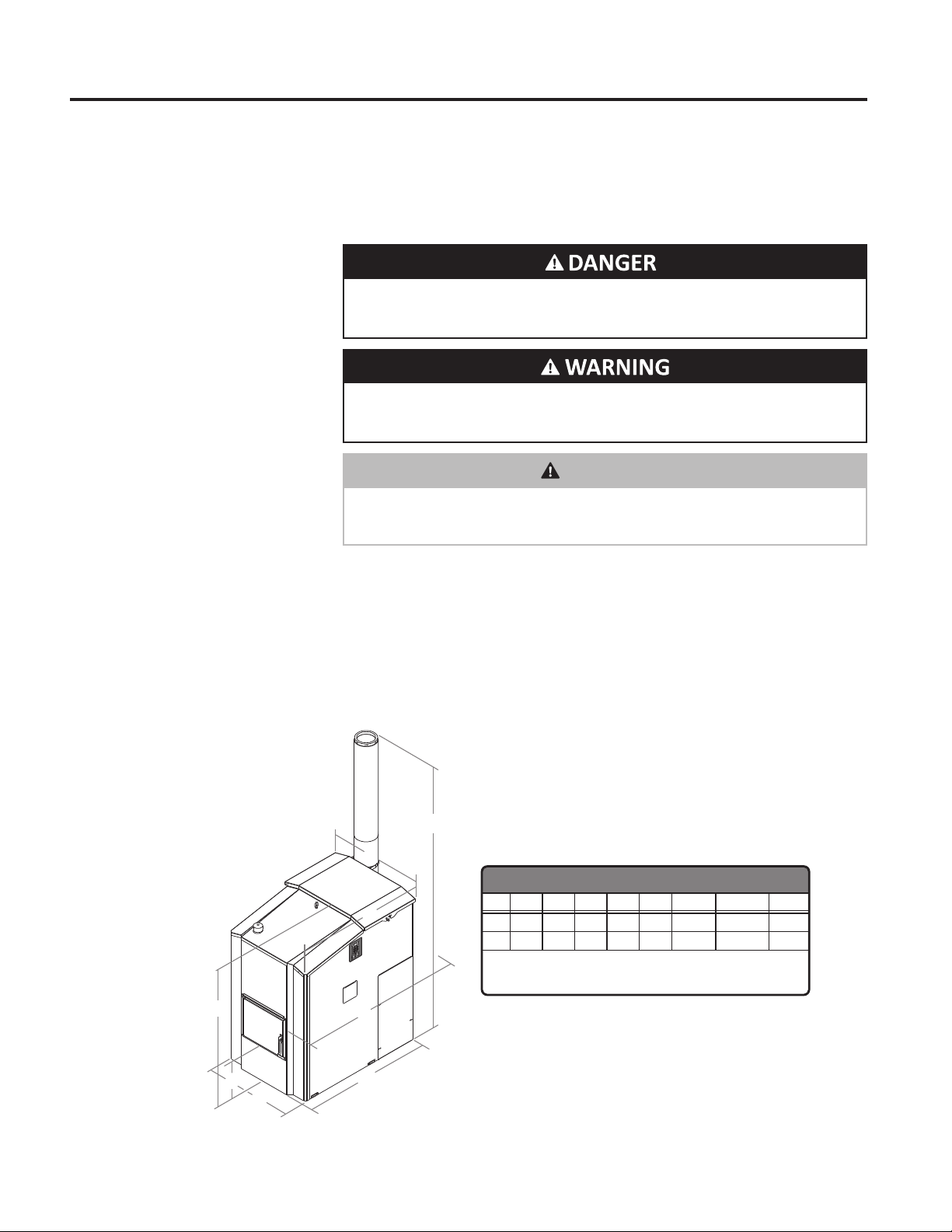
Maintain the following clearances from combustibles for the
furnace installation:
• 8" (20 cm) from the transition box
• 6" (15 cm) from the sides
• 48" (122 cm) from the front
• 8" (20 cm) from the chimney
• 27" (68.5 cm) from the top
• The foundation must be noncombustible
Do not allow combustible materials (straw, hay or wood) near
the outdoor furnace. Keep the perimeter of the outdoor furnace
clear and clean.
All covers must be maintained at all times except during
maintenance, inspection and service.
Never leave the rebox door or hopper lid open or ajar when
unattended.
This heater is designed to burn premium quality wood pellets
only.* Higher eciencies and lower emissions generally result
when burning premium quality wood pellets, as compared to
standard pellets. DO NOT BURN: unseasoned wood, garbage,
tires, lawn clippings, leaves, brush trimmings or general yard
waste, materials containing asbestos, materials containing
lead, mercury or other heavy toxic metals, materials containing
plastic,materialscontainingrubber, wastepetroleumproducts,
paints and paint thinners, asphalt products, chemicals, coal,
glossy or colored paper, construction and demolition debris,
plywood, particleboard, salt water driftwood and other
previously salt water saturated materials, manure, animal
carcasses and asphalt products. Burning these materials may
result in release of toxic fumes or render the heater ineective
and cause smoke.
Never use gasoline, gasoline-type lantern fuel, kerosene,
charcoal lighter uid, or similar liquids to start or ‘freshen up’a
re in this outdoor furnace. Keep all such liquids well away from
the outdoor furnace while it is in use.
Use only those listed fuels recommended by the manufacturer
of your unit. Never use the following: trash, plastics, gasoline,
rubber, naptha, household garbage, material treated with
petroleum products (particle board, railroad ties and pressure
treated wood), leaves, paper products, and cardboard.
NOTE: Chloride or sulfurous gases can be generated if plastic or
rubber is burned and will mix with the moisture from the wood
and form hydrochloric or sulfuric acids in the rebox, creating
corrosion.
Always wear the appropriate personal protective gear when
cleaning ash from the rebox.
CAUTION
Failure to maintain and clean heat exchangers properly can
result in the thermal valve activating.
NOTE: At least one circulation pump must run continuously to
ensure proper operation of the outdoor furnace.