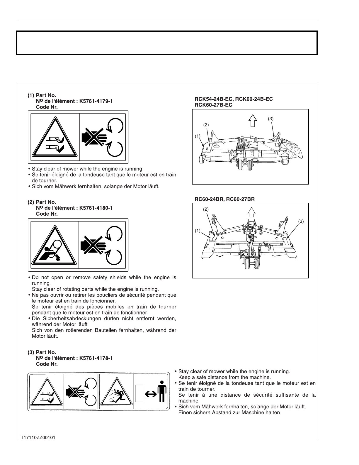
2
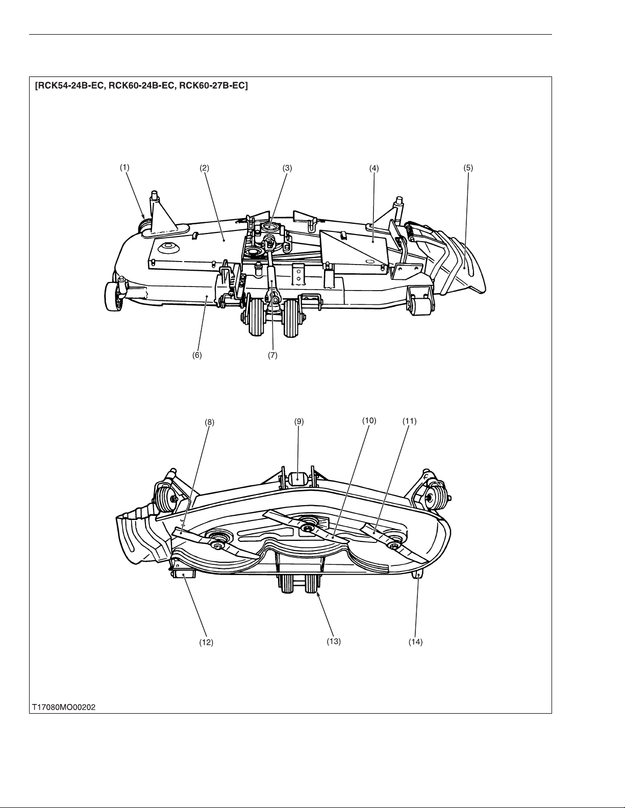
RCK54/60-24B-EC · RCK60-27B-EC · RC60-24/27BR, WSM SAFETY INSTRUCTIONS
SAFETY STARTING
• Do not start the engine by shorting across starter
terminals or bypassing the safety start switch.
• Do not alter or remove any part of machine safety
system.
• Before starting the engine, make sure that all shift
levers are in neutral positions or in disengaged
positions.
• Never start the engine while standing on ground.
Start the engine only from operator’s seat.
SAFETY WORKING
• Do not work on the machine while under the influence
of alcohol, medication, or other substances or while
fatigued.
• Wear close fitting clothing and safety equipment
appropriate to the job.
• Use tools appropriate to the work. Markshift tools,
parts, and procedures are not recommended.
• When servicing is performed together by two or more
persons, take care to perform all work safely.
• Do not work under the machine that is supported
solely by a jack. Always support the machine by
safety stands.
• Do not touch the rotating or hot parts while the engine
is running.
• Never remove the radiator cap while the engine is
running, or immediately after stopping. Otherwise, hot
water will spout out from radiator. Only remove
radiator cap when cool enough to touch with bare
hands. Slowly loosen the cap to first stop to relieve
pressure before removing completely.
• Escaping fluid (fuel or hydraulic oil) under pressure
can penetrate the skin causing serious injury. Relieve
pressure before disconnecting hydraulic or fuel lines.
Tighten all connections before applying pressure.
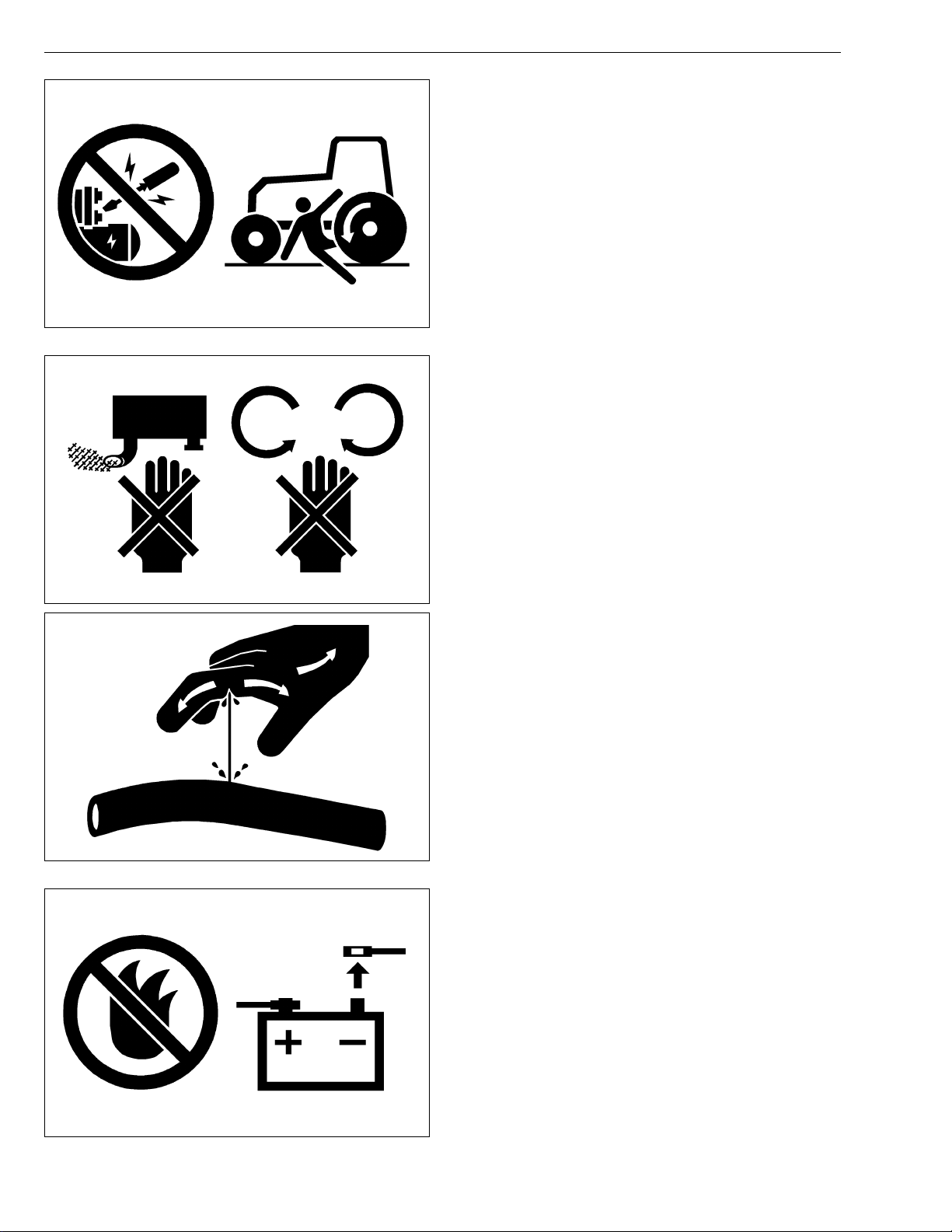
AVOID FIRES
• Fuel is extremely flammable and explosive under
certain conditions. Do not smoke or allow flames or
sparks in your working area.
• To avoid sparks from an accidental short circuit,
always disconnect the battery negative cable first and
connect it last.
• Battery gas can explode. Keep sparks and open
flame away from the top of battery, especially when
charging the battery.
• Mark sure that no fuel has been spilled on the engine.