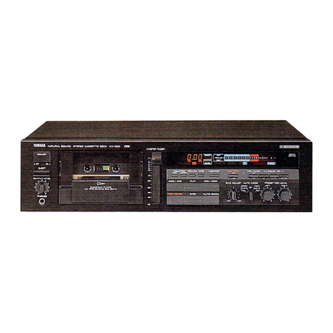
Yamaha KX-E300 User manual

SERVICE MANUAL
■ CONTENTS
TO SERVICE PERSONNEL . . . . . . . . . . . . . . . . . . . 2
REAR PANELS . . . . . . . . . . . . . . . . . . . . . . . . . . . 2–3
SPECIFICATIONS . . . . . . . . . . . . . . . . . . . . . . . . . . . 3
DIMENSIONS . . . . . . . . . . . . . . . . . . . . . . . . . . . . . . . 4
INTERNAL VIEW . . . . . . . . . . . . . . . . . . . . . . . . . . . . 4
DISASSEMBLY PROCEDURES/分解手順 . . . . . 5–7
ADJUSTMENTS/調整 . . . . . . . . . . . . . . . . . . . . 8–12
DISPLAY DATA . . . . . . . . . . . . . . . . . . . . . . . . . . . . 13
IC DATA . . . . . . . . . . . . . . . . . . . . . . . . . . . . . . . 14–15
BLOCK DIAGRAM . . . . . . . . . . . . . . . . . . . . . . . . . . 16
PRINTED CIRCUIT BOARD . . . . . . . . . . . . . . . 17–20
SCHEMATIC DIAGRAM . . . . . . . . . . . . . . . . . . . . . 21
PARTS LIST . . . . . . . . . . . . . . . . . . . . . . . . . . . . 23–33
PARTS LIST FOR CARBON RESISTORS . . . . . . . 34
This manual has been provided for the use of authorized YAMAHA Retailers and their service personnel.
It has been assumed that basic service procedures inherent to the industry, and more specifically YAMAHA Products, are already known and understood by the users,
and have therefore not been restated.
WARNING: Failure to follow appropriate service and safety procedures when servicing this product may result in personal injury, destruction of expensive
components, and failure of the product to perform as specified. For these reasons, we advise all YAMAHA product owners that any service
required should be performed by an authorized YAMAHA Retailer or the appointed service representative.
IMPORTANT: The presentation or sale of this manual to any individual or firm does not constitute authorization, certification or recognition of any applicable
technical capabilities, or establish a principle-agent relationship of any form.
The data provided is believed to be accurate and applicable to the unit(s) indicated on the cover. The research, engineering, and service departments of YAMAHA
are continually striving to improve YAMAHA products. Modifications are, therefore, inevitable and specifications are subject to change without notice or obligation
to retrofit. Should any discrepancy appear to exist, please contact the distributor's Service Division.
WARNING: Static discharges can destroy expensive components. Discharge any static electricity your body may have accumulated by grounding yourself to
the ground buss in the unit (heavy gauge black wires connect to this buss).
IMPORTANT: Turn the unit OFF during disassembly and part replacement. Recheck all work before you apply power to the unit.
IMPORTANT NOTICE
100807
SERVICE MANUAL
KX-E300
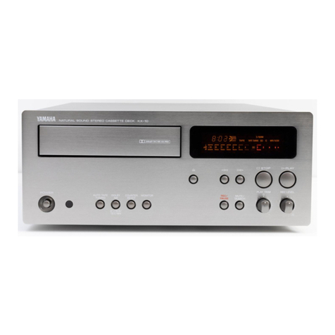
STEREO CASSETTE DECK
KX-E300
For the system operation of KX-E300, please refer to Service Manual #100805 for the CRX-E300/NX-E300.
本機の「システム動作」については、CRX-E300/NX-E300のサービスマニュアル100805をご覧ください。
KX-E300
KX-E300
2
■ TO SERVICE PERSONNEL
1. Critical Components Information
Components having special characteristics are marked Z
and must be replaced with parts having specifications equal
to those originally installed.
2. Leakage Current Measurement (For 120V Models Only)
When service has been completed, it is imperative to verify
that all exposed conductive surfaces are properly insulated
from supply circuits.
●Meter impedance should be equivalent to 1500 ohm shunted
by 0.15µF.
●Leakage current must not exceed 0.5mA.
●Be sure to test for leakage with the AC plug in both
polarities.
AC LEAKAGE
TESTER OR
EQUIVALENT
EQUIPMENT
UNDER TEST
INSULATING
TABLE
WALL
OUTLET
WARNING: CHEMICAL CONTENT NOTICE!
The solder used in the production of this product contains LEAD. In addition, other electrical/electronic and/or
plastic (where applicable) components may also contain traces of chemicals found by the California Health and
Welfare Agency (and possibly other entities) to cause cancer and/or birth defects or other reproductive harm.
DO NOT PLACE SOLDER, ELECTRICAL/ELECTRONIC OR PLASTIC COMPONENTS IN YOUR MOUTH FOR
ANY REASON WHATSOEVER!
Avoid prolonged, unprotected contact between solder and your skin! When soldering, do not inhale solder fumes
or expose eyes to solder/flux vapor!
If you come in contact with solder or components located inside the enclosure of this product, wash your hands
before handling food.
■REAR PANELS
▼ U, C models
▼ B, G models

KX-E300
KX-E300
3
▼ J model
Type /型式
Auto Reverse
4-Track 2-Channel Playback/Recording
Stereo Cassette Deck
Heads /ヘッド
REC/PB Hard permalloy
Erase Double Gap Ferrite
Motors /モーター
Main DC servo motor
Tray Loading DC motor
Wow & Flutter /ワウフラッター
W.PEAK (EIAJ) ±0.19 %
W.RMS 0.09 %
Fast Winding Time /早巻時間
about 100 seconds (C-60 tape)
Frequency Response /総合周波数特性
Type I (Normal) 30 –15,000 Hz ±3 dB
Type II (CrO2) 30 –16,000 Hz ±3 dB
Type IV (Metal) 30 –18,000 Hz ±3 dB
S/N Ratio /SN比
U, C, B, G models
(S : 3rd harmonic distortion 3 %, N : Weighted)
NR off 58 dB
Dolby B NR on 66 dB
Dolby C NR on 74 dB
J model (S : 0 dB, N : Weighted)
NR off 54 dB
Dolby B NR on 62 dB
Dolby C NR on 70 dB
Harmonic Distortion /歪率
1.0 %
Channel Separation /セパレーション
40 dB or more
Crosstalk (125 Hz) /クロストーク
55 dB or more
Input Sensitivity/Impedance /入力端子
Line 100 mV/30 kΩ
Output Level /出力端子
Line 570 mV/3.0 kΩ
Power Requirements /電源電圧
U, C models AC120 V, 60 Hz
B, G models AC230 V, 50 Hz
J model AC100 V, 50/60 Hz
Power Consumption /消費電力
U, C, B, G models 12 W (Standby 3W)
J model 9 W (Standby 3W)
Dimensions (W x H x D) /寸法(幅 X高さX 奥行)
217 x 88 x 291 mm
(8-9/16" x 3-7/16" x 11-7/16")
Weight /重量
3.0 kg (6 lbs 10 oz.)
Finish /仕上げ
Silver color U, C, B, G, J models
Gold color U, C, G models
Accessories /付属品
Audio Pin Cable x 2, System Control Cable x 1
* Specifications are subject to change without notice.
U ........ U.S.A. model
C ........ Canadian model
B ........ British model
G........ European model
J........ Japanese model
■SPECIFICATIONS
Dolby noise reduction manufactured under license from Dolby
Laboratories Licensing Corporation.
“DOLBY”and the double-D symbol Vare trademarks of Dolby
Laboratories Licensing Corporation.
VDOLBY B-C NR
V

KX-E300
KX-E300
4
■DIMENSIONS
■INTERNAL VIEW
qMAIN P.C.B. (4)
wCassette Mechanism Unit
eMAIN P.C.B. (1)
rMAIN P.C.B. (2)
tMAIN P.C.B. (3)
Unit : mm (inch)
217 (8-9/16")
8
(5/16")
80 (3-1/8")
88 (3-7/16")
6
(3/16")
10
(3/8")
275 (10-13/16")
291 (11-7/16")
qe
r
t
w

KX-E300
KX-E300
5
■DISASSEMBLY PROCEDURES/分解手順
Remove parts in disassembly order as numbered.
1. Removal of Top Cover
a. Remove 4 screws (q) and 4 screws (w) in Fig. 1.
b. Lift the Top Cover at the rear and move it rearward
slantingly.
2. Removal of Front Panel
a. Disconnect 2 connectors (CB201 and CB209) in Fig. 2.
b. Remove 2 screws (e) and 2 screws (r) in Fig. 1.
c. Detach the 2 hooks in Fig. 1 and then pull the Front
Panel forward.
3. Removal of Cassette Mechanism Unit
a. Remove 4 screws (t) in Fig. 1.
b. Disconnect 3 connectors (CB1, CB2 and CB3) in Fig. 3.
c. Remove the Cassette Mechanism Unit in Fig. 1.
1. トップカバーの外し方
qw
2. フロントパネルの外し方
er
3. カセットメカユニットの外し方
t
(番号順に取り外しを行ってください。)
e
e
r
t
t
q
Cassette Mechanism Unit
Hook
Front Panel
Hook
Top Cover
w
q
Fig. 1
Fig. 2
CB201
CB209

KX-E300
KX-E300
6
4. Removal of Cassette Mechanism
a. Remove 4 screws (y) in Fig. 3.
b. Detach the hook in Fig. 3 and then pull out the
Cassette Mechanism.
5. Removal of Main Motor
Remove 2 screws (u) in Fig. 3.
6. Removal of Pinch Roller
Detach the hook and then remove the Pinch Roller in
Fig. 4.
7. Removal of Head Ass’y
a. Remove 1 screw (i) and then remove the Relay
P.C.B. in Fig. 4.
b. Remove 2 screws (o) and then remove the Head
Ass’y in Fig. 4.
* Perform the azimuth adjustment after installing the
Head Ass’y.
CB3
CB2 CB1
F/R Belt
Main
Belt
Main
Motor
Hook
yy
y
y
uu
Hook
Relay P.C.B
Hook
Pinch Roller (R)
Pinch Roller (L)
Head Ass'y
oio
Fig. 3
Fig. 4
4. カセットメカの外し方
y
5. メインモーターの外し方
u
6. ピンチローラーの外し方
7. ヘッドの外し方
i
o

KX-E300
KX-E300
7
●サービスポジション
!0
!1
!2 !3
●Service Position
a. Remove 3 screws (!0) in Fig. 5.
b. Remove 1 screw (!1) in Fig. 6.
c. Remove 2 screws (!2) and 1 screw (!3) in Fig. 7.
d. Remove the Main P.C.B.
e. Place the Main P.C.B. as shown in Fig. 8 and check
them for operation.
Fig. 5
Fig. 7
Fig. 6 Fig. 8
MAIN (2)
MAIN (1)
!0
!0
!1
!2
!2
!3
Cloth

KX-E300
KX-E300
8
1.Before adjustment
●Since head magnetization, dust accumulations, etc.
are likely to introduce error in the various characteris-
tics, it is very important that the heads are properly
demagnetized and cleaned.
●Make adjustments of mechanical system, playback
system and recording system in that order.
●Except for azimuth adjustment, adjust in the forward
direction.
2.Instruments required
●Audio frequency oscillator
●ACVM or dual channel (ACVM)
●DCVM
●Wow/flutter meter
●Oscilloscope
●Frequency counter
●Torque meter
TW-2111A (TX911580) ....Take up/back tension (FWD)
TW-2121A (TX911570) .....Take up/back tension (RVS)
CT-160L (TX911120) ...................................... FF/REW
3.Test tape required
●MTT-111N (TX911650) ... Normal speed
●MTT-114N (TX911680) ... Azimuth
●MTT-212N (TX911660) ... Playback level
●MTT-256 (TX911300)...... Playback frequency re-
sponse (Normal)
●MTT-356 (TX911310)...... Playback frequency re-
sponse (CrO2)
●Reference tape
Type I/Normal (LH) ............... TDK AC225 (VU167200)
Type II/High (CrO2) ............... TDK AC514 (VU167300)
Type IV/METAL ..................... TDK AC713 (VU167400)
■ADJUSTMENTS/調整
1. 調整の前に
2. 使用測定器
●
●
●
●
●
●
●
3. テストテープ
●
●
●
●
●
●

KX-E300
KX-E300
9
TEST MODE (Operation and Display Check)
Enter the TEST MODE by pressing the STANDBY/ON
button while pressing the STOP button and rbutton
when the power is OFF.
テストモード(動作・ディスプレイチェック)
r
DISPLAY (Light all segment) /ディスプレイ全灯 DISPLAY CHECK (Light a segment of each grid)
/ディスプレイ表示チェック(各グリッドの1ヶ所を点灯)
1 PLAY PLAY Playback mode without the cassette tape. (Head cleaning mode)
2 STOP STOP To stop the playback mode.
3 DIRECTION DIRECTION To change the playback direction in the playback mode.
4rDIMMER
To change concentration of the display in the photograph mode at each pressing of the rbutton (6 steps).
5ePHOTO MODE Photograph mode. Same display as No.4 but without concentration change.
6 DOLBY NR All display segments lit.
7 REC/PAUSE Version To display the program version and date when pressing the REC/PAUSE button.
8 MODE Display grid and segments short/open check. (Fig. A is OK)
9 COUNTER RESET EXIT To exit the TEST MODE and return to the normal mode.
10 STANDBY/ON EXIT To exit the TEST MODE and power off.
NO. BUTTON FUNCTION ACTION
● TEST POINT
MAIN (1)
VR203VR204
R
RLL
VR201VR202
VR101 VR103
L
RVR104
MAIN (2)
TAPE SPEED ADJ.
RECORDING BIAS ADJ.
PLAYBACK LEVEL ADJ.
RECORDING LEVEL ADJ.
Azimuth adjustment
screw. (REVERSE)
Azimuth adjustment
screw. (FORWARD)
Rec out L: ch 1
Rec out R: ch 2
DC input, X-Y (Resurge) mode
NG
OK
0.2V
0.2V
Fig. A
Fig. B

KX-E300
KX-E300
10
“MECHANICAL ADJUSTMENT”
Item to be
Adjusted
Check each
torque
Check FF, REW
take up time
Azimuth
Tape Speed
Wow/Flutter
Tape
CT-160L (FF, REW)
TW-2111A (FWD)
TW-2121A (RVS)
AC-514 (C-60)
MTT-114N
10kHz, –10dB
MTT-111N
3kHz, –10dB
MTT-111N
3kHz, –10dB
Step
1
2
3
4
5
Mode
FF REW
PLAY
FF REW
PLAY
PLAY
PLAY
Rating
FF, REW torque : within 70—150g/cm.
Take up torque : 30—70g/cm.
Back tension : 1.5—6g/cm.
80 to 120 seconds.
Playback output of L and R is maxi-
mum and phase difference should
be minimum both directions. (Fig. B)
*3000 Hz
Less than 0.19% (WRMS)
Remarks
After the adjustment
make sure to apply
screw lock paint.
Take measurement at
about the center of the
test tape. Perform ad-
justment in the forward
direction and check the
tape speed in the re-
verse direction.
Take measurement at
about the center of the
test tape.
Instrument
required
Torque
meter
ACVM
Oscilloscope
Frequency
counter
Wow/flutter
meter
Adjustment
part
Azimuth
adjustment
screw. (Fig. B)
VR101
メカ調整
調整項目
各トルクの確認
FF、REW時
間の確認
アジマス
テープスピード
ワウ・フラッター
の確認
テストテープ
CT-160L(FF,REW)
TW-2111A(FWD)
TW-2121A(RVS)
AC-514(C-60)
MTT-114N
10kHz,−10dB
MTT-111N
3kHz,−10dB
MTT-111N
3kHz,−10dB
Step
1
2
3
4
5
モード
FFREW
PLAY
FFREW
PLAY
PLAY
PLAY
調整方法&規格
FF、REWトルク:70〜150g/cm
テイクアップ:30〜 70g/cm
バックテンション:1.5〜6g/cm
80〜120秒
再生レベルが最大で左右の位相
差が最小となるように調整す
る。(Fig.B)
*3000Hz
0.19%(WRMS)以下
備考
調整後、必ずネジ
ロックを施すこと。
テストテープの中央
付近で測定すること。
フォワード方向で調整し、
リバース方向でテープス
ピードを確認すること。
テストテープの中央
付近で測定すること。
測定器
トルクメー
ター
ACVM
オシロスコープ
周波数
カウンター
ワウ・フラッ
ターメーター
調整箇所
アジマス
調整ネジ
(Fig.B)
VR101
+ 30
- 15
+30
-15
*モーターまたはカセットメカ交換後は、モーターの初期特性を補うために 2980Hz に設定します。
+30
-15
* After replacing the motor or cassette mechanism, perform adjustment in the rating of 2980 Hz to compensate the motor’s initial
characteristic.
+ 30
- 15

KX-E300
KX-E300
11
“ELECTRICAL ADJUSTMENT”
●Use 560 mV (250 nwb/m) for 0 dB as the standard level of the unit.
0dB = 250 nwb/m (315 Hz) = –7 dBV (Rec out level)
Item to be
Adjusted
Playback
level (315Hz)
Confirmation of
playback frequency
response
Step
1
2
Rating
–5 dBV ±0.3 dBV
Check that the 10kHz playback
level is within 0 ±3 dB of the
1kHz playback level. (Fig. C)
Adjustment
parts
VR201 (L ch)
VR202 (R ch)
Tape
MTT-212N
315Hz,
250nwb/m
Test tape for frequency check.
3180µs + 120µs (LH) (MTT-256)
3180µs+70µs (CrO2) (MTT-356)
Points of
measurement
LINE OUT
LINE OUT
Mode
PLAY
PLAY
Instrument
required
ACVM
ACVM
Oscilloscope
< Playback section >
Fig. C
±4dB ±3.5dB
1k
±3dB
±3dB
3k 10kHz31525050 12.5kHz
●PLAYBACK FREQUENCY RESPONSE
<Recording section >
Rating
Adjust for equal record and
playback levels.
(–25 dBV ±0.3 dBV)
Adjust for equal record and
playback levels.
(–25 dBV ±0.5 dBV)
Perform recording/playback
and confirm that the fre-
quency response shown in
Fig. D is obtained.
If not, perform adjustment
again at High (CrO2) so that
the frequency response in
Fig. D is obtained.
Perform recording/playback
and confirm that there is no
output level difference.
(–25 dBV ±0.5 dBV)
If the value is not as speci-
fied, perform adjustment
again according to Steps 1
and 2.
Item to be
Adjusted
Recording
level
Recording
bias
(Total
frequency
response)
Confirmation
of recorded
level
Step
1
2
3
Points of
measurement
LINE OUT
LINE OUT
LINE OUT
Mode
REC
PLAY
REC
PLAY
REC
PLAY
Instrument
required
ACVM
Audio
frequency
oscillator
ACVM
Audio
frequency
oscillator
ACVM
Audio
frequency
oscillator
Measurement
conditions
Input 315 Hz Signal
to LINE IN from Audio
Frequency Oscillator.
Adjust output level of
Audio Frequency Os-
cillator so that the
voltage of LINE OUT
becomes –25 dBV.
Input 12.5 kHz Signal
to LINE IN from Audio
Frequency Oscillator.
Adjust output level of
Audio Frequency Os-
cillator so that the
voltage of LINE OUT
becomes –25 dBV.
Tape
AC-514
High
(CrO2)
AC-514
High
(CrO2)
AC-225
Normal
(LH)
AC-514
High
(CrO2)
Adjustment
parts
VR203 (L ch)
VR204 (R ch)
VR103 (L ch)
VR104 (R ch)
●TOTAL FREQUENCY RESPONSE ( –20 dBV)
Dolby NR OFF / B on / C on
Type I(Normal) / Type II (High) / Type IV (METAL)
Fig. D
±4dB ±4dB
1k
±3dB
±3dB
3k 10kHz31525050 12.5kHz

KX-E300
KX-E300
12
〈録音系の調整〉
調整方法& 規格
録音/再生を行い、出力レ
ベル差がないようにする。
(ー25dBV± 0.3dBV)
録音/再生を行い、出力レ
ベル差がないようにする。
(ー25dBV± 0.5dBV)
録音/再生を行い、FigDの
規格を満足することを確認
する。
満足しない場合は、再度
High(CrO2)で調整を行
い、FigDの規格を満足する
こと。
録音/再生を行い、出力レ
ベル差がないことを確認す
る。(ー25dBV±0.3dBV)
規格値外の場合は、ステッ
プ1、2を再調整する。
調整項目
録音レベル
録音バイア
ス
録・再周波
数特性
録音レベル
の確認
Step
1
2
3
測定箇所
LINEOUT
LINEOUT
LINEOUT
モード
REC
PLAY
REC
PLAY
REC
PLAY
測定器
ACVM
周波数カウン
ター
ACVM
周波数カウン
ター
ACVM
周波数カウン
ター
測定条件
LINEINに 315Hzの
信号を加え、LINE
OUT の出力レベル
が‐25dBVとなるよ
うに発振器の出力レ
ベルを調整する。
LINEINに12.5kHz
の信号を加え、LINE
OUT の出力レベル
が‐25dBVとなるよ
うに発振器の出力レ
ベルを調整する。
テープ
AC-514
High
(CrO2)
AC-514
High
(CrO2)
AC-225
Normal
(LH)
AC-514
High
(CrO2)
調整箇所
VR203(Lch)
VR204(Rch)
VR103(Lch)
VR102(Rch)
Fig. C
±4dB ±3.5dB
1k
±3dB
±3dB
3k 10kHz31525050 12.5kHz
● 再生周波数特性 ●録再周波数特性(-20dBV)
Dolby NR OFF / B on / C on
Type I(Normal) / Type II (High) / Type IV (METAL)
Fig. D
±4dB ±4dB
1k
±3dB
±3dB
3k 10kHz31525050 12.5kHz
電気系調整
〈再生系の調整〉
調整項目
再生レベル
(315Hz)
再生周波数
特性の確認
Step
1
2
規格
-5dBV±0.3dBV
Fig.Cの規格を満足すること。
調整箇所
VR201(Lch)
VR202(Rch)
テープ
MTT-212N
315Hz,
250nwb/m
3180μs + 120μs(LH)(MTT-256)
3180μs + 70μs(CrO
2
)(MTT-356)
測定箇所
LINEOUT
LINEOUT
モード
PLAY
PLAY
測定器
ACVM
ACVM
オシロスコープ

KX-E300
KX-E300
13
■ DISPLAY DATA
PATTERN AREA
11018 31
●V301: BJ707GNK (V358690)
●PIN CONNECTION
●GRID ASSIGNMENT
●ANODE CONNECTION
Pin No. 12345678910111213141516171819202122232425262728293031
F1 F1 NP P1 P2 P3 P4 P5 P6 P7 NX NX NX NX NX NX NX 1G 2G 3G 4G 5G 6G 7G 8G 9G
10G 11G
NP F2 F2
Connection
Note : 1) F1, F2 ..... Filament 2) NP ..... No pin 3) NX ..... No extended pin 4) 1G ~ 11G ..... Grid
1G 2G 3G 4G 5G 6G 7G 8G 9G 10G 11G
P1aaaa S1S1S1S1
P2bbbb B1B1B1B1
P3cccc B2B2B2B2
P4dddd B3B3B3B3
P5eeee –B4 B4 B4 B4
P6ffff –B5 B5 B5 B5
P7gggg––B6 B6 B6 B6

KX-E300
KX-E300
14
■ IC DATA
A-D Convert
(10 bit x 12 ch)
Serial I/O
Serial I/O 2 (Clock
synchronization/UART)
Serial I/O 1 (Clock synchronization)
(256 byte automatic transmission)
Buzzer output
Watch dog timer
Port P0 (8)
8
ROM
RAM
Interrupt controller
LCD display
40 Control terminals
(36 register port)
PWM1 (8 bit)
PWM0 (14 bit)
Timer System clock
Timer X (16 bit)
Timer 1 (8 bit)
Timer 2 (8 bit)
Timer 3 (8 bit)
Timer 4 (8 bit)
Timer 5 (8 bit)
Timer 6 (8 bit)
X
IN
- X
OUT
(Main clock)
X
CIN
- X
COUT
(Sub clock)
Internal peripheral function
I/O Port
CPU core
Memory
Port P5 (8)
8
Port P6 (6)
6
Port P7 (8)
8
Port P8 (8)
8
Port P9 (2)
2
Port P1 (8)
8
Port P2 (8)
8
Port P3 (8)
8
Port P4 (8)
7
1
64 P2
0
/Buz
02
/FLD
0
63 P2
1
/FLD
1
62 P2
2
/FLD
2
61 P2
3
/FLD
3
60 P2
4
/FLD
4
59 P2
5
/FLD
5
58 P2
6
/FLD
6
57 P2
7
/FLD
7
56 P0
0
/FLD
8
55 P0
1
/FLD
9
54 P0
2
/FLD
10
53 P0
3
/FLD
11
52 P0
4
/FLD
12
51 P0
5
/FLD
13
50 P0
6
/FLD
14
49 P0
7
/FLD
15
48 P1
0
/FLD
16
47 P1
1
/FLD
17
46 P1
2
/FLD
18
45 P1
3
/FLD
19
44 P1
4
/FLD
20
43 P1
5
/FLD
21
42 P1
6
/FLD
22
41 P1
7
/FLD
23
40 P3
0
/FLD
24
39 P3
1
/FLD
25
38 P3
2
/FLD
26
37 P3
3
/FLD
27
36 P3
4
/FLD
28
35 P3
5
/FLD
29
34 P3
6
/FLD
30
33 P3
7
/FLD
31
32 P8
0
/FLD
32
31 P8
1
/FLD
33
30 P8
2
/FLD
34
29 P8
3
/FLD
35
28 V
EE
27 P8
4
/FLD
36
26 P8
5
/RTP
0
/FLD
37
25 P8
6
/RTP
1
/FLD
38
P5
7
/S
RDV2
/S
CLK22
P5
6
/S
CLK21
P5
5
/TxD
P5
4
/RxD
P5
3
/S
CLK12
P5
2
/S
CLK11
P5
1
/S
OUT1
P5
0
/S
IN1
AV
SS
V
REF
P6
5
/S
STB1
/AN
11
P6
4
/INT
4
/S
BUSY1
/AN
10
P6
3
/AN
0
P6
2
/S
RDY1
/AN
8
P7
7
/AN
7
P7
6
/AN
6
65
66
67
68
69
70
71
72
73
74
75
76
77
78
79
80
P7
5
/AN
5
P7
4
/AN
4
P7
3
/AN
3
P7
2
/AN
2
P7
1
/AN
1
P7
0
/AN
0
P6
1
/CNTR
0
/CNTR
2
P6
0
/CNTR
1
P4
7
/INT
2
RESET
P9
1
/X
COUT
P9
0
/X
CIN
V
SS
X
IN
X
OUT
V
CC
P4
6
/T
SOUT
P4
5
/T
1OUT
P4
4
/PWM
1
P4
3
/B
UZ01
P4
2
/INT
3
P4
1
/INT
1
P4
0
/INT
0
P8
7
/PWM
0
/FLD
39
1
2
3
4
5
6
7
8
9
10
11
12
13
14
15
16
17
18
19
20
21
22
23
24
IC205 : M38B57M6-143FP (XW379B00)

KX-E300
KX-E300
15
Pin No.
PORT I/O IN OUT
RESISTOR
1 P75/AN5 I Mecha SW1 AD(PLAY, Half) PU
2 P74/AN4 I Loading SW AD(IN,OUT) PU
3 P73/AN3 I Meter L AD(-30 –+6)
4 P72/AN2 I Meter R AD(-30 –+6)
5 P71/AN1 I Operation 2
AD(FF,REW,REC,COU,EJ)
PU
6 P70/AN0 I Operation 1
AD(ST,PL,DIR,DOL,MOD)
PU
7 P61/CN0,2 O DOLBY-B B : H
8 P60/CN1 O DOLBY-OFF OFF : H PU
9 P47/INT2 I AC Pulse
10 RESET I Reset Reset : L PU
11 P91/XCO O METAL METAL : H
12 P90/XCI O HIGH HIGH : H
13 VSS GND
14 XIN 4MHz
15 XOUT 4MHz
16 VCC Vu
17-22 P41-P46 I (Pull down) PD
23 P40/INT0 I Power SW ON : L PU
24 P87/PWM O REC MUTE ON : L (PWMControl)
25-27 P84-P86 I (Pull down) PD
28 VEE -22V
29 P83/FL35 I Power ON ON : H
30 P82/FL34 O FL-DIG11 ON : H PD
31 P81/FL33 O FL-DIG10 ON : H PD
32 P80/FL32 O FL-DIG9 ON : H PD
33 P37/FL31 O FL-DIG8 ON : H
34 P36/FL30 O FL-DIG7 ON : H
35 P35/FL29 O FL-DIG6 ON : H
36 P34/FL28 O FL-DIG5 ON : H
37 P33/FL27 O FL-DIG4 ON : H
Pin No.
PORT I/O IN OUT
RESISTOR
38 P32/FL26 O FL-DIG3 ON : H
39 P31/FL25 O FL-DIG2 ON : H
40 P30/FL24 O FL-DIG1 ON : H
41-48 P10-P17 O (Open)
49 P07/FL15 I (Open)
50 P06/FL14 O FL-SEG7 ON : H
51 P05/FL13 O FL-SEG6 ON : H
52 P04/FL12 O FL-SEG5 ON : H
53 P03/FL11 O FL-SEG4 ON : H
54 P02/FL10 O FL-SEG3 ON : H
55 P01/FL9 O FL-SEG2 ON : H
56 P00/FL8 O FL-SEG1 ON : H
57-64 P20-P27 I (Pull down) PD
65 P57/SC22 I SYS-IN
66 P56/SC21 O SYS-OUT
67 P55/TD I Reel pulse
68 P54/RD O Solenoid ON : H PD
69 P53/SC12 O Main motor ON : H PD
70 P52/SC11 O Loading IN : H PD
71 P51/SO1 O Loading+ OUT : H PD
72 P50/SI1 O N/H/M NOR:L,HIGH:M,MET:H
73 AVSS GND
74 VREF +5V
75 P65/AN11 O BIAS ON : L PU
76 P64/AN10 O REC/PB PB : L PD
77 P63/AN9 I (Pull down) PD
78 P62/AN8 O LINE MUTE ON : L PD
79 P77/AN7 I Mecha SW3
AD(Error erase F,Error erase R)
PU
80 P76/AN6 I Mecha SW2 AD(70,METAL) PU
AD INPUT PORT
PIN NAME VOLTAGE AREA STANDARD VOLTAGE MODE
6 AN0 (ope 1) 4.58 –5.00 5.00 OFF
3.75 –4.58 4.17 –
2.92 –3.75 3.34 MODE
2.10 –2.92 2.51 DOLBY
1.25 –2.10 1.67 DIREC.
0.41 –1.25 0.83 PLAY
0.00 –0.41 0.00 STOP
5 AN1 (ope 2) 4.58 –5.00 5.00 OFF
3.75 –4.58 4.17 –
2.92 –3.75 3.34 EJECT
2.10 –2.92 2.51 COUN.
1.25 –2.10 1.67 REC
0.41 –1.25 0.83 REW
0.00 –0.41 0.00 FF
IC205 : M38B57M6-143FP (XW379B00)

KX-E300
KX-E300
16
T401
POWER ON
(Q115, 116)
FILAMENT
POWER ON
TAPE SELECTOR
(Q108,109)
POWER ON
POWER
SUPPLY
IC103
IC104
Q117
Q120
-22V
VU5
+12V
VA
FL DISPLAY
M
M
MAIN MOTOR
SOLENOID
LOADING MOTOR
CASSETTE
MECHA
LOADING
UNIT
DOLBY B/C NR
(IC203)
OPERATION
SWITCH
(SW301~311)
µCOM
IC205
LOADING
CONTROL
(IC101)
MECHA CONTROL
(VR101, Q101,104)
MECHA SENSOR
SYSTEM
CONNECTOR
(JK101)
REEL PULSE
RESET
A/D
AC PULSE
METER LEVEL
TAPE SELECTOR
DOLBY CONT
er
ty@3
!1!2&2
o
@9
!0
ui
BIAS ON/OFF &5
REC MUTE @4
LINE MUTE &8
R/P CONT &6
^7
w
&0&1
e@0
e
t
i
o
r
!3
q
u
q&9*0
^8^9
#0~$0
%0~%6
REC LEVEL
(VR301)
REC LEVEL
(VR203,204)
BIAS ADJ.
(VR103,104)
PB LEVEL
(VR201,202)
MPX
(FI201,202)
PB AMP.
(IC202)
REC AMP.
(IC204)
EQ
R/P CONT
(IC201)
LINE IN LINE OUT
R/P HEAD
REC IN
w@1 o!4
t!8 !3 !0r!9
PB IN REC OUT
y!7
LINE OUT
ERASE
HEAD
r
METER DRIVER
(IC102)
METER LEVEL
70µON/OFF
(Q201,202)
LINE MUTE
(Q113,114)
R/P CONT (Q203,204)
TAPE SELECTOR
BIAS ON/OFF
(Q112,122)
REC MUTE
DOLBY CONT (Q205,206)
105kHz
(FI203,204)
!5 w!4!6
BIAS OSC
L101, Q106,107
y
w
i
^5 ^6
■ BLOCK DIAGRAM

ABCDE FGH
1
2
3
4
5
6
KX-E300
17
■PRINTED CIRCUIT BOARD (Foil side)
●Semiconductor Location
Ref. No. Location
D108 E4
D115 F4
D116 F4
D117 F4
D118 F4
Q101 C2
Q102 C2
Q103 C3
Q104 C3
Q105 C3
Q106 C3
Q107 C3
Q108 E3
Q109 E3
Q110 D3
Q111 E3
Q112 D2
Q113 F3
Q114 F3
Q115 E3
Q116 E3
Q117 E4
Q118 E3
Q119 E3
Q120 E3
Q121 E3
Q122 D2
IC101 E4
IC102 E3
IC103 E3
IC104 F3
P.C.B. MAIN (1) (Lead Type Devices)
Vu5
SYN
GU
LM
LIR
LIL
GA
VA
LOR
LOL
INOUT
SYSTEM
CONNECTOR
AC3
AC4
AC5
AC6
F1
F2
From : MAIN (4)
LIS
GM
LOS
L-
L+
TAPE SPEED ADJ. RECORDING BIAS ADJ
To/From : CASSETTE MECHA
RRS
MES
FRS
HS
70S
SO
RP
+5V
PLS
MO
GM
MB
MA
q
F1
F2
-22V
REP
SOL
MOT
LO-
LO+
BIAS
MSW3
MSW2
MSW1
LSW
MR
ML
P-ON
ACP
+5V
HIGH
MET
ER
GE
RR
PL
GB
To/From : MAIN (2)
To : MAIN (2)
w
Point q(Both end of C105) REC mode
V : 20V/div H : 5 µsec/div
DC range 1 : 1 probe
0V
Point w
CH1 : Pin 10 of IC205
CH2 : OUT of IC103
V : 2V/div (CH1) V : 5V/div (CH2)
H : 0.5 sec/div DC range 1 : 1 probe
CH 1
CH 2
*
AC POWER ON
*
AC POWER OFF

ABCDE FGH
1
2
3
4
5
6
KX-E300
18
■PRINTED CIRCUIT BOARD (Foil side)
●Semiconductor Location
Ref. No. Location
D101 C2
D102 B2
D103 E3
D104 E2
D105 E3
D106 E3
D107 F3
D109 E2
D110 F2
D111 F3
D112 F3
D113 F3
D114 F3
D119 F2
P.C.B. MAIN (1) (Surface Mount Devices)
P.C.B. MAIN (4) (Lead Type Devices)
F2
F1
AC6
AC5
AC4
AC3
To : MAIN (1)

ABCDE FGH
1
2
3
4
5
6
KX-E300
19
■PRINTED CIRCUIT BOARD (Foil side)
●Semiconductor Location
Ref. No. Location
D201 D4
D202 D4
D203 D4
D204 D4
D205 D4
D206 D4
D207 D4
D208 F4
D209 D4
IC205 C4
●Semiconductor Location
Ref. No. Location
Q201 E2
Q202 E2
Q203 D2
Q204 D2
Q205 D2
Q206 D2
Q209 D2
Q211 D2
Q212 D2
IC201 E2
IC202 D2
IC203 F2
IC204 G2
P.C.B. MAIN (2) (Lead Type Devices)
P.C.B. MAIN (2) (Surface Mount Devices)
we
To : MAIN (3)
F2
F1 S1
S2 S3
S4 S5
S6 S7
D1 D2
D3 Gu
D4 D5
D6 D7
D8 D9
D10 D11
PSW OPE1
OPE2 Gu
To/From : MAIN (3)
LIR
DIR
GA
DIL
LIL
PLAYBACK LEVEL ADJ.
To/From : R/P & ER HEADS
RECORDING LEVEL ADJ.
Vu5
SYN
GU
LM
LIR
LIL
GA
VA
LOR
LOL
To/From : MAIN (1)
ER
GE
RR
PL
GB
From : MAIN (1)
F1
F2
-22V
REP
SOL
MOT
LO-
LO+
BIAS
MSW3
MSW2
MSW1
LSW
MR
ML
P-ON
ACP
+5V
HIGH
MET
PL
RL
GA
RR
PR
GE
ER
Point e(Pin 15 of C205) REC mode
V : 2V/div H : 0.1 µsec/div
DC range 1 : 1 probe
0V
Point w
CH1 : Pin 10 of IC205
CH2 : OUT of IC103
V : 2V/div (CH1) V : 5V/div (CH2)
H : 0.5 sec/div DC range 1 : 1 probe
CH 1
CH 2
*
AC POWER ON
*
AC POWER OFF

ABCDE FGH
1
2
3
4
5
6
KX-E300
20
■PRINTED CIRCUIT BOARD (Foil side)
P.C.B. MAIN (3) (Lead Type Devices)
P.C.B. MAIN (3) (Surface Mount Devices)
From : MAIN (2)
Gu
OPE2 OPE1
PSW D11
D10 D9
D8 D7
D6 D5
D4 Gu
D3 D2
D1 S7
S6 S5
S4 S3
S2 S1
F1 F2
To/From : MAIN (2)
LIR
DIR
GA
DIL
LIL
STANDBY/ON
COUNTER
RESET
MODE
31
1
REC/
PAUSE
DOLBY NR
REC LEVEL DIRECTION
Other manuals for KX-E300
1
Table of contents
Other Yamaha Cassette Player manuals

Yamaha
Yamaha MT100II User manual

Yamaha
Yamaha KX-W602 User manual

Yamaha
Yamaha MT2X User manual

Yamaha
Yamaha KX-690 User manual

Yamaha
Yamaha K-1020 User manual

Yamaha
Yamaha KX-E100 User manual

Yamaha
Yamaha KX-230 User manual

Yamaha
Yamaha KX-W302 User manual

Yamaha
Yamaha KX-E300 User manual

Yamaha
Yamaha MT50 User manual

Yamaha
Yamaha K-540 User manual

Yamaha
Yamaha MT3X User manual

Yamaha
Yamaha MT44 User manual

Yamaha
Yamaha KX-500A User manual

Yamaha
Yamaha KX-W382 User manual

Yamaha
Yamaha KX-650 RS User manual

Yamaha
Yamaha K-1020 User manual

Yamaha
Yamaha K-1020 User manual

Yamaha
Yamaha K-220 User manual

Yamaha
Yamaha K-98 User manual