manuals.online logo
Brands
  1. Home
  2. •
  3. Brands
  4. •
  5. Yamaha
  6. •
  7. Stereo System
  8. •
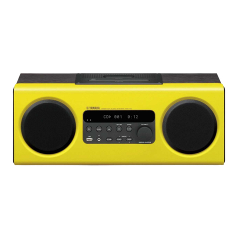
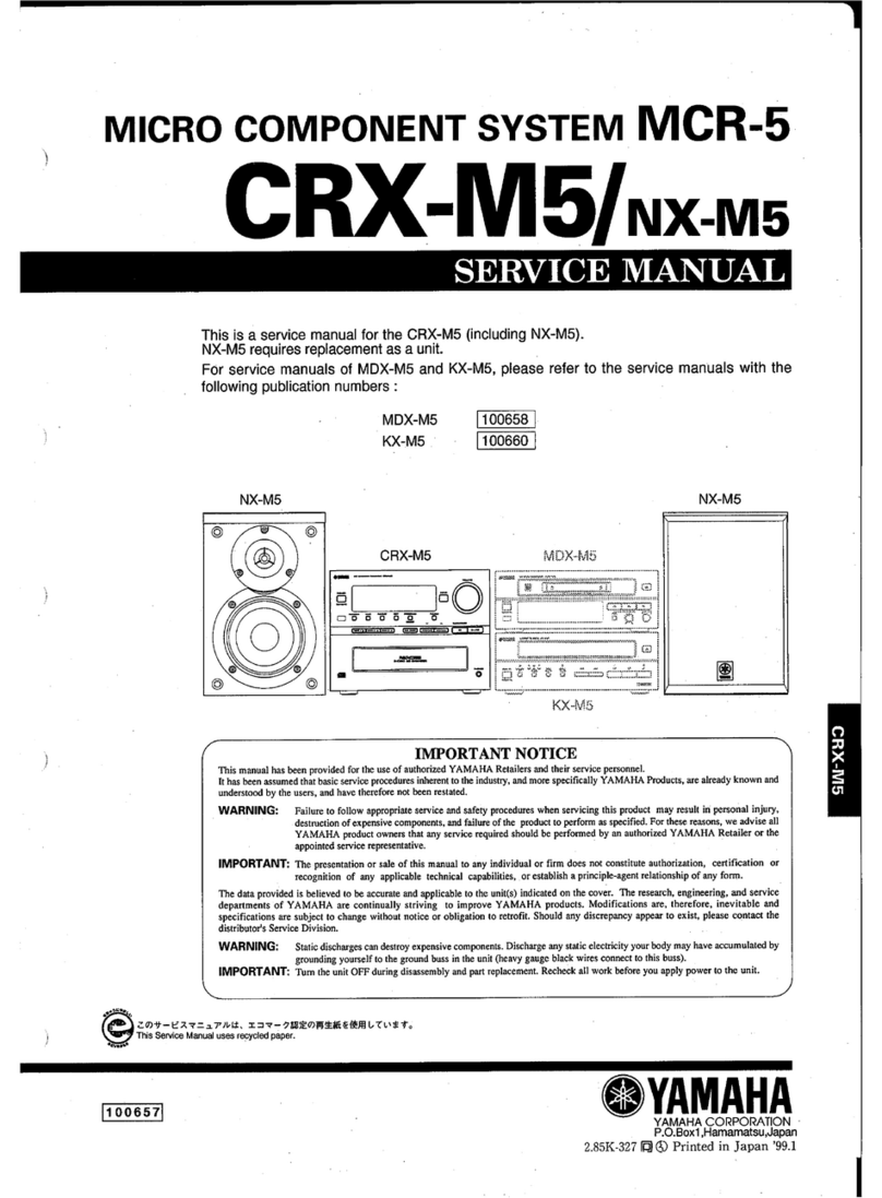
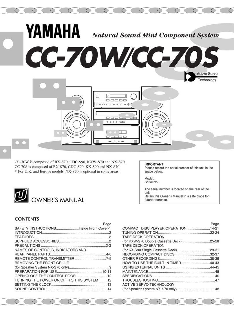
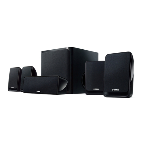
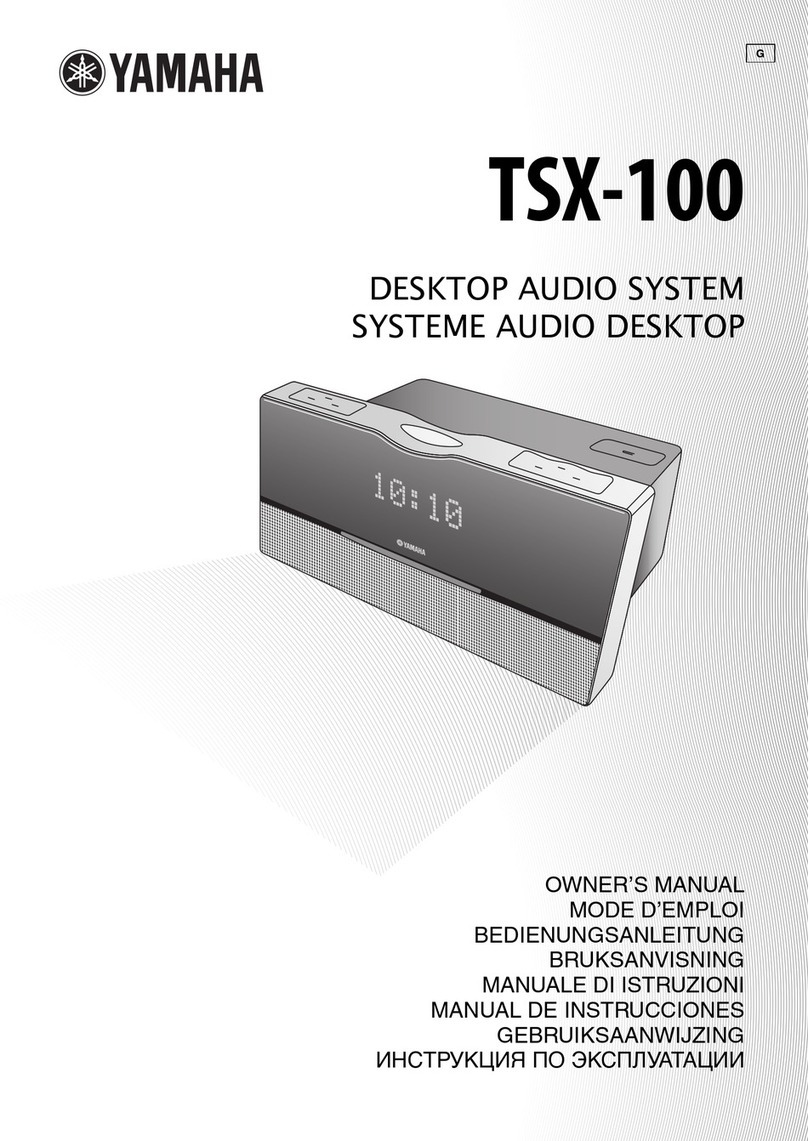
  9. Yamaha TSX-10 User manual

Yamaha TSX-10 User manual

E
\f\\\\I"HA
illll\llii:illll:~~t~'O
(~15
'$.'J.;.;
..
~.~~.{,.;:i./.:%i.Z£,'.!!,.·.".:!.if.:M:.;,.!!,.'.f'.{~,.'.f
.•
',;.f,.:
.•,
.•..
i.
"'\"
...
~o
i!!f!i;;JJ!W"~
/!//:",:oi,j'/:.-i;·.---.··
TABLETOP
STEREO,.nl
SYSTEM
HIFI
TABl,lmi
OWNER'S
MODE;P'~
BEDIENUNGSANE.",i.·,E.f
..
,.·.,.·
....
~ilni.
BRUKSAN'VISr
MANUALE
DI
IS"F
..
'
MANUAL
DE
INSTRU
GEBRUIKS
CAUTION
Use of controls or adjustments or performance of
procedures other than those specified herein may
result in hazardous radiation exposure.
ATTENTION
Cemploi de commandes, de reglages ou un choix
de procedures differents des specifications de cette
brochure peut entrainer une exposition a
d’eventuelles radiations pouvant etre dangereses.
ACHTUNG
Die Verwendung von Bedienungselementen oder
Einstellungen oder die Durchfuhrung von
Bedienungsvorgangen, die nicht in dieser Anleitung
aufgefijhrt sind, kann zu einem Kontakt mit
gefahrlichen Laserstrahlen fuhren.
OBSERVERA
Anvandning av kontroller och justeringar eller
genomfdrande av andra procedurer an de som
specificeras i denna bok kan resultera i att du
utsatter dig for farlig straining.
ATTENZIONE
Uso di controlli o regolazioni o procedure non
specificamente descritte puo causare I’esposizione
a radiazioni di livello pericoloso.
PFlECAUCldN
El uso de 10scontroles o 10sprocedimientos de
ajuste o utilization diferentes de 10sespecificados
en este manual pueden causal una exposition
peligrosa a la radiation.
VOORZICHTIG
Gebruik van bedieningsorganen of instellingen, of
uitvoeren van handelingen anders dan staan
beschreven in deze handleiding kunnen leiden tot
blootstelling aan gevaarlijke stralen.
VARO!
AVATTAESSA JA SUOJALUKITUS
OHITETTAESSA OLET ALTTIINA
NiiKYMiiTToMiiLLE LASERSiiTEILYLLE. iiLii
KATSO SLiTEESEEN.
VARNING!
OSYNLIG LASERSTRALNING NliR DENNA DEL
AR~PPNAD~CHSPARRENARURK~PPLAD.
BETRAKTA EJ STRALEN.
*: This label alsoshowsthe model number,required
voltage andpower consumption of this unit, andother
cautions,etc.
ARNN
S
N\.
I)!lil
.."
=n
CE:
®
==
I"
..
..
Z
IQ
Q
Z
II.:::::~~.
II.~
......
-.
CLASS
1
LASER
PRODUCT
LASER
KIASSE
1
PRODUKT
LUOKAN
1
LASERLAITE
KLASS
1
LASER
APPARAT
,-
.~
RGYGH/RYG
RR
G"R
[EljNA
00.
All
lmWl00i
SPARRAR
All
lJlKllPPlAIE.
s
RAwJ
All
ARL
.
ARC
!AA
AE5SA.v.
SOOJALlJ(
us
DH
E
AE5SA
IU
AL
NA
~
IW.E
JA
A
~
AO
IW.E
LASERSll
EL
1.1£.
lI1Jl
KA
so
slI
EESEEN.
CAUI1lJ'J
•
V9IIlE
ANDI
R RR IMi P
R K F
)(Jl
R M
*:
This label also shows the model number, required
voltage and power consumption
of
this unit, and other
cautions, etc.
CAUTION
Use of controls or adjustments or performance of
procedures other than those specified herein may
result
in
hazardous radiation exposure.
ATTENTION
L'emploi de commandes, de reglages
ou
un choix
de procedures differents des specifications de cette
brochure peut entrainer une exposition a
d'eventuelles radiations pouvant etre dangereses.
ACHTUNG
Die Verwendung von Bedienungselementen oder
Einstellungen oder die DurchfOhrung von
Bedienungsvorgangen, die nicht
in
dieser Anleitung
aufgefOhrt sind, kann
zu
einem Kontakt mit
gefahrlichen Laserstrahlen
fOhren.
OBSERVERA
Anvandning av kontroller och justeringar eller
genomforande av andra procedurer
an
de som
specificeras idenna bok kan resultera iatt du
utsatter dig for farlig straining.
ATTENZIONE
Uso di controlli 0regolazioni 0procedure non
specificamente descritte
pUb
causare I'esposizione
aradiazioni di Iivello pericoloso.
PRECAUCION
EI
uso de los controles 0los procedimientos de
ajuste 0utilizaci6n diferentes de los especificados
en
este manual pueden causar una exposici6n
peligrosa a
la
radiaci6n.
VOORZICHTIG
Gebruik van bedieningsorganen of instellingen, of
uitvoeren van handelingen anders dan staan
beschreven
in
deze handleiding kunnen leiden tot
blootstelling aan gevaarlijke stralen.
VAROI
AVATTAESSA JA SUOJALUKITUS
OHITETTAESSA OLET ALTTIINA
NAKYMATTOMALLE LASERSATEILYLLE. ALA
KATSO SATEESEEN.
VARNING!
OSYNLlG LASERSTRALNING NAR DENNA DEL
AR OPPNAD OCH SPARREN AR URKOPPLAD.
BETRAKTA
EJ
STRALEN.
Thank you for purchasingthis YAMAHA product. We
hopeit will give you many yearsof trouble-free
enjoyment. For thebestperformance,readthis manual
carefully. It will guide you in operating your YAMAHA
product.
This owner’s manualcoversthreepackagesTSX-10,
TSX- 15andTSX-20.
Pleasecheck thepackagenumberof your product andits
componentsby refering to thefollowing table.
Package number Components
CD receiver Speaker system
TSX-10 CRX-TS 10 NX-TS 10
TSX-15 CRX-TS20 NX-TS 10
TSX-20 CRX-TS20 NX-TS20
l
Output Powe Channel
18
W + 18 W ( R, 1 kHz, 10% THD)
l
Installation-free design
l
Full Operation Remote Control
l
Multi-Function Timer/Sleep Timer
l
SUBWOOFER Output Terminal
Tuner
l
40-Station FM/AM Preset Tuning
l
Multi-Function RDS Reception
CD Player
l
S-bit DAC and 8fs Digital Filter
l
Optical Digital Output
l
Random and Repeat Play
Speakers
l
2-Way Bass-Reflex Speaker System
Magnetic Shielding Type
After unpacking,checkthatthefollowing partsareincluded.
l
Remote control
l
AM loop antenna
l
Stand x 3
l
Indoor FM antenna
l
Battery (CR2025)
Q
I
l
Speakercable x 2
l
Mounting bracket
0
.
\
0
0
l
Screw x 9
CY
+
l
Paperpattern
ic;’
l
Non-slip pad x 4
1
ENGLISH
INTRODUCTION
Thank you for purchasing this YAMAHA product. We
hope it will give you many years
of
trouble-free
enjoyment. For the best performance, read this manual
carefully.
It
will guide you in operating your YAMAHA
product.
This owner's manual covers three packages TSX-lO,
TSX-15 and TSX-20.
Please check the package number
of
your product and its
components by refering to the following table.
Package number Components
CD receiver Speaker system
TSX-IO CRX-TSIO NX-TSIO
TSX-15 CRX-TS20 NX-TSIO
TSX-20 CRX-TS20 NX-TS20
FEATURES
•Output Powe Channel
18 W+18 WI
0,
1kHz, 10% THD)
•Installation-free design
•
Full
Operation Remote Control
•Multi-Function Timer/Sleep Timer
•SUBWOOFER Output Terminal
Tuner
•40-Station
FM/AM
Preset Tuning
•Multi-Function
RDS
Reception
CD
Player
•S-bit
DAC
and 8fs Digital Filter
•Optical Digital Output
•Random and Repeat Play
Speakers
•2-Way Bass-Reflex Speaker System
Magnetic Shielding Type
SUPPLIED ACCESSORIES
After unpacking, check that the following parts
are
included.
•Remote control •AM loop antenna •Stand x 3 • Screw x 9
1
•Paper pattern
•Mounting bracket
•Non-slip pad x 4
•Indoor FM antenna
•Speaker cable x 2
@YAMAHA
•Battery (CR2025)
Front panel ..........................................................
.4
Display.. ..............................................................
.4
Remote control ....................................................
5
Connections .........................................................
6
Installation ...........................................................
8
CD preventive care ............................................10
Remote control ..................................................11
Setting the clock ................................................12
Adjusting the brightness of the display .............12
CD play.. ............................................................14
Selecting the time display.. ................................15
Random-sequenceplay ......................................15
Repeatplay ........................................................16
Listening to the radio.. .......................................17
Presetting stations..............................................18
Receiving RDS data ..........................................19
PTY SEEK mode..............................................
.20
Optional settings for RDS functions ................
.21
Timer play ........................................................
.22
Sleeptimer.. ......................................................
.23
Troubleshooting .................................................
24
Specifications ...................................................
.26
When not using the stands
When using the stands
50mm
2l
Set up this system by allowing spacesspecified in the figure or more around and behind the main unit to assure good ventilation.
To prevent the ventilation holes from being obstructed, be sure not to place another unit or any object on top of the main unit.
Otherwise, it may cause fire or damage to the main unit.
Cautions
l
If the main unit is put inside a rack, the front of it must be fully open.
l
When mounting this system on the wall, allow spaces specified in the figure around the system as well, however,
the space between the system and the wall is determined by the mounting bracket and screws used.
l
When mounting this system on the wall, make sure that there is no metalic projection on the wall. If a metallic
projection get into an opening of the main unit, it may cause fire or an electric shock to the user.
2
CONTENTS
INTRODUCTION 1
FEATURES 1
SUPPLIED ACCESSORIES 1
SETTING UP THIS SYSTEM 2
PRECAUTIONS 3
NAMES
OF
BUTTONS
AND
CONTROLS
Front panel 4
Display 4
Remote control 5
GETTING STARTED
Connections 6
Installation 8
CD preventive care
~
10
Remote control
11
Setting the clock
12
Adjusting the brightness
of
the display 12
LISTENING TO ASOURCE
13
SETTING UP THIS SYSTEM
When not using the stands
COMPACT DISC PLAYER OPERATIONS
CD play 14
Selecting the time display
15
Random-sequence play
15
Repeat play 16
TUNER OPERATIONS
Listening to the radio
17
Presetting stations 18
RECEIVING RDS STATIONS
Receiving RDS data 19
PTY SEEK mode 20
Optional settings for RDS functions
21
USING THE BUILT-IN TIMER
Timer play 22
Sleep timer 23
ADDITIONAL
INFORMATION
Troubleshooting 24
Specifications 26
When using the stands
400mm
....----.100mm
SWd
10mm
50mm
400mm
Set up this system by allowing spaces specified
in
the figure or more around and behind the main unit to assure good ventilation.
To prevent the ventilation holes from being obstructed, be sure not to place another unit or any object on top
of
the main unit.
Otherwise, it may cause fire or damage to the main unit.
Cautions
•If the main
unit
is put inside arack, the front
of
it
must be fUlly open.
•When mounting
this
system on the wall, allow spaces specified in the figure around the system as well, however,
the space between the system and the wall is determined by the mounting bracket and screws used.
•When mounting this system on the wall, make sure that there is no metalic projection on the wall. If ametallic
projection get into
an
opening
of
the main unit,
it
may cause fire
or
an electric shock
to
the user.
2
1
2
3
4
5
6
7
8
9
10
11
12
13
14
To assurethe best performance, please read this manual
carefully. Keep it in a safe place for future reference.
To avoid humming sounds, position this system away
from other electrical appliances, motors and
transformers. To prevent fire or electrical shock, do not
place this system where it may get exposed to rain or
any kind of liquid.
Avoid extreme temperature fluctuations or excessive use
of a humidifier in the room where this system is
installed to prevent condensation inside this system,
which may cause an electrical shock, fire damage to this
unit, and/or personal injury.
In order not to obstruct heat radiation, do not cover the
main unit with a newspaper, a tablecloth, a curtain, etc.
If the temperature inside the main unit rises, it may
cause fire, damage to the main unit and/or personal
injury.
Avoid installing this system in a place where foreign
objects and liquid might fall. It might causea fire,
damage to this system and/or personal injury. Do not
place the following objects on this system:
l
Other components,asthey may causedamageand/or
discolor the surfaceof this system.
l
Burning objects (i.e., candles),asthey may causefire,
damageto this systemand/or personalinjury.
l
Containers with liquid in them, asthey may causean
electrical shock to the userand/or
damage
to
thissystem.
Do not use force on switches, controls or connection
cables. Never pull the cables when disconnecting them.
Only the voltage specified on the main unit must be
used. Using this system with a higher voltage than
specified is dangerous and may result in fire or other
accidents. YAMAHA will not be held responsible for
any damage resulting from the use of this system with a
voltage
otherthanthatspecified.
Placing the speakers on the same shelf or rack asthe
turntablecanresultin howling.
Secureplacementor installationis theowner’s
responsibility.
YAMAHA shall not be liable for any accident caused by
improper placement or installation of this system.
Any
timeyounotedistortion,
reduce the volume to a
lower setting. Never allow the amplifier to be driven
into “clipping”. Otherwise the speakersmay be
damaged.
Do not attempt to clean this system with chemical
solvents;
thismight damagethefinish.Use
a clean, dry
cloth.
Disconnect the power cord from the wall outlet when
not planning to use this system for a long period of time,
or
duringanelectricalstorm,asit couldbedamagedby
lightning.
Do notattemptto modify or fix this systemyourself.
Contact qualified YAMAHA service personnel when
any service is needed. The cabinet should never be
opened for any reason.
Be sure
toreadthe“Troubleshooting”sectionregarding
common operating errors before concluding that this
system is faulty.
The main unit is not disconnectedfrom the AC power
sourceaslong asit is connectedto thewall outlet, even
if the unit itself is turned off. This stateis called the
standbymode.In this state,theunit is designedto
consumea very small quantity of power.
CAUTION FORCARRYING THE MAIN UNIT
Before carrying the main unit, first remove thedisc
from theunit, press
STANDBY/ON
to turn the unit
off, thendisconnectthe AC power plug from the
wall outlet.
SPECIAL INSTRUCTIONS FOR U.K. MODEL
IMPORTANT:
The wires in the mains leadarecoloured in accordance
with the following code:
Blue: NEUTRAL
Brown: LIVE
As thecolours of the wires in the mainsleadof this
apparatusmay not correspondwith thecoloured
markings identifying the terminals in your plug,
proceedasfollows: The wire which is coloured BLUE
must beconnectedto the terminal which is marked
with the letter N or coloured BLACK. The wire which
is coloured BROWN must beconnectedto the terminal
which is marked with the letter L or colouredRED.
Making surethat neither core is connectedto theearth
terminal of thethreepin plug.
For U.K. customers
If the socketoutlets in thehome arenot suitablefor the
plug supplied with this appliance,it shouldbecut off and
anappropriate3 pin plug fitted. For details, refer to the
instructions describedabove.
Note:
The plug severedfrom the mainsleadmust be
destroyed,asaplug with baredflexible cord is hazardous
if engagedin a live socketoutlet.
CAUTION
Useof controls or adjustmentsor performanceof
proceduresother than thosespecified herein may
result in hazardousradiation exposure.
CLASS 1 LASER PRODUCT
ASER KIASSE 1 PRODUKT
LUOKAN 1 LA!iiERLAlTE
KLA!Zi 1 LASER APPARAT
This compactdisc
player is classified asa
CLASS 1LASER
product.
The CLASS 1LASER
PRODUCT label is
locatedon therear
panel.
The lasercomponentin this product is capableof
emitting radiation exceedingthe limit for Class 1.
3
PRECAUTIONS: READ THIS BEFORE OPERATING THIS SYSTEM
CAUTION
This compact disc
player is classified as a
CLASS I
LASER
product.
The CLASS I
LASER
PRODUCT
label is
located on the rear
panel.
CLASS
1
LASER
PRODUCT
LASER
KLASSE
1
PRODUKT
LUOKAN
1
LASERLAITE
KLASS
1
LASER
APPARAT
Use
of
controls
or
adjustments
or
performance
of
procedures other than those specified herein may
result in hazardous radiation exposure.
IMPORTANT:
The
wires in the mains lead are coloured in accordance
with the following code:
The
main unit is not disconnected from the AC
power
source as long as it is connected to the wall outlet, even
if
the unit itselfis turned off. This state is called the
standby mode. In this state, the unit is designed to
consume avery small quantity
of
power.
CAUTION
FOR
CARRYING
THE
MAIN
UNIT
Before carrying the main unit, first remove the disc
from the unit, press STANDBY/ON to turn the unit
off, then disconnect
the
AC
power
plug from the
wall outlet.
SPECIAL
INSTRUCTIONS
FOR
U.K. MODEL
As
the colours
of
the wires in the mains lead
of
this
apparatus may not correspond with the coloured
markings identifying the terminals in your plug,
proceed as follows:
The
wire which is coloured
BLUE
must be connected to the terminal which is marked
with the letter N
or
coloured BLACK. The wire which
is coloured
BROWN
must
be
connected to the terminal
which is marked with the letter L
or
coloured RED.
Making sure that neither core is connected to the earth
terminal
of
the three
pin
plug.
Blue:
NEUTRAL
Brown:
LIVE
For
U.K.
customers
If
the socket outlets in the
home
are not suitable for the
plug supplied with this appliance, it should be cut
off
and
an appropriate 3pin plug fitted.
For
details, refer to the
instructions described above.
Note: The plug severed from the mains lead must
be
destroyed, as aplug with bared flexible cord is hazardous
if
engaged in alive socket outlet.
1
To
assure the best performance, please read this manual
carefully. Keep
it
in
asafe place for future reference.
2
To
avoid humming sounds, position this system away
from other electrical appliances, motors and
transformers.
To
prevent fire or electrical shock, do not
place this system where
it
may get exposed
to
rain or
any kind
of
liquid.
3Avoid extreme temperature fluctuations or excessive use
of
ahumidifier in the room where this system
is
installed to prevent condensation inside this system,
which may cause
an
electrical shock, fire damage
to
this
unit, and/or personal injury.
4In order not
to
obstruct heat radiation,
do
not cover the
main unit with anewspaper, atablecloth, acurtain, etc.
If
the temperature inside the main unit rises,
it
may
cause fire, damage
to
the main unit and/or personal
injury.
5Avoid installing this system
in
aplace where foreign
objects and liquid might fall.
It
might cause afire,
damage
to
this system and/or personal injury. Do not
place the following objects on this system:
•Other components,
as
they
may
cause damage and/or
discolor
the
surface of
this
system.
•Buming objects (i.e., candles),
as
they
may
cause
fire,
damage
to
this
system and/or personal
injury.
•Containers
with
liquid
in
them,
as
they
may
cause
an
electrical shock
to
the
user and/or
damage
to
this
system.
6Do not use force on switches, controls or connection
cables. Never pull the cables when disconnecting them.
7Only the voltage specified on the main unit must
be
used. Using this system with ahigher voltage than
specified
is
dangerous and may result
in
fire or other
accidents. YAMAHA will not be held responsible for
any damage resulting from the use
of
this system with a
voltage other than that specified.
8Placing the speakers on the same shelfor rack
as
the
turntable can result
in
howling.
9Secure placement or installation
is
the owner's
responsibility.
YAMAHA shall not be liable for any accident caused by
improper placement or installation
of
this system.
10
Any time you note distortion, reduce the volume
to
a
lower setting. Never allow the amplifier
to
be
driven
into "clipping". Otherwise the speakers may be
damaged.
11
Do not attempt to clean this system with chemical
solvents; this might damage the finish. Use aclean, dry
cloth.
12 Disconnect the power cord from the wall outlet when
not planning to use this system for along period
of
time,
or during
an
electrical storm,
as
it
could
be
damaged by
lightning.
13 Do not attempt
to
modify or
fix
this system yourself.
Contact qualified YAMAHA service personnel when
any service is needed. The cabinet should never be
opened for any reason.
14 Be sure
to
read the "Troubleshooting" section regarding
common operating errors before concluding that this
system is faulty.
The laser component in this product is capable
of
emitting radiation exceeding the limit for Class
1.
3
PRECAUTIONS: READ THIS BEFORE OPERATING THIS SYSTEM
CAUTION
This compact disc
player is classified as a
CLASS I
LASER
product.
The CLASS I
LASER
PRODUCT
label is
located on the rear
panel.
CLASS
1
LASER
PRODUCT
LASER
KLASSE
1
PRODUKT
LUOKAN
1
LASERLAITE
KLASS
1
LASER
APPARAT
Use
of
controls
or
adjustments
or
performance
of
procedures other than those specified herein may
result in hazardous radiation exposure.
IMPORTANT:
The
wires in the mains lead are coloured in accordance
with the following code:
The
main unit is not disconnected from the AC
power
source as long as it is connected to the wall outlet, even
if
the unit itselfis turned off. This state is called the
standby mode. In this state, the unit is designed to
consume avery small quantity
of
power.
CAUTION
FOR
CARRYING
THE
MAIN
UNIT
Before carrying the main unit, first remove the disc
from the unit, press STANDBY/ON to turn the unit
off, then disconnect
the
AC
power
plug from the
wall outlet.
SPECIAL
INSTRUCTIONS
FOR
U.K. MODEL
As
the colours
of
the wires in the mains lead
of
this
apparatus may not correspond with the coloured
markings identifying the terminals in your plug,
proceed as follows:
The
wire which is coloured
BLUE
must be connected to the terminal which is marked
with the letter N
or
coloured BLACK. The wire which
is coloured
BROWN
must
be
connected to the terminal
which is marked with the letter L
or
coloured RED.
Making sure that neither core is connected to the earth
terminal
of
the three
pin
plug.
Blue:
NEUTRAL
Brown:
LIVE
For
U.K.
customers
If
the socket outlets in the
home
are not suitable for the
plug supplied with this appliance, it should be cut
off
and
an appropriate 3pin plug fitted.
For
details, refer to the
instructions described above.
Note: The plug severed from the mains lead must
be
destroyed, as aplug with bared flexible cord is hazardous
if
engaged in alive socket outlet.
1
To
assure the best performance, please read this manual
carefully. Keep
it
in
asafe place for future reference.
2
To
avoid humming sounds, position this system away
from other electrical appliances, motors and
transformers.
To
prevent fire or electrical shock, do not
place this system where
it
may get exposed
to
rain or
any kind
of
liquid.
3Avoid extreme temperature fluctuations or excessive use
of
ahumidifier in the room where this system
is
installed to prevent condensation inside this system,
which may cause
an
electrical shock, fire damage
to
this
unit, and/or personal injury.
4In order not
to
obstruct heat radiation,
do
not cover the
main unit with anewspaper, atablecloth, acurtain, etc.
If
the temperature inside the main unit rises,
it
may
cause fire, damage
to
the main unit and/or personal
injury.
5Avoid installing this system
in
aplace where foreign
objects and liquid might fall.
It
might cause afire,
damage
to
this system and/or personal injury. Do not
place the following objects on this system:
•Other components,
as
they
may
cause damage and/or
discolor
the
surface of
this
system.
•Buming objects (i.e., candles),
as
they
may
cause
fire,
damage
to
this
system and/or personal
injury.
•Containers
with
liquid
in
them,
as
they
may
cause
an
electrical shock
to
the
user and/or
damage
to
this
system.
6Do not use force on switches, controls or connection
cables. Never pull the cables when disconnecting them.
7Only the voltage specified on the main unit must
be
used. Using this system with ahigher voltage than
specified
is
dangerous and may result
in
fire or other
accidents. YAMAHA will not be held responsible for
any damage resulting from the use
of
this system with a
voltage other than that specified.
8Placing the speakers on the same shelfor rack
as
the
turntable can result
in
howling.
9Secure placement or installation
is
the owner's
responsibility.
YAMAHA shall not be liable for any accident caused by
improper placement or installation
of
this system.
10
Any time you note distortion, reduce the volume
to
a
lower setting. Never allow the amplifier
to
be
driven
into "clipping". Otherwise the speakers may be
damaged.
11
Do not attempt to clean this system with chemical
solvents; this might damage the finish. Use aclean, dry
cloth.
12 Disconnect the power cord from the wall outlet when
not planning to use this system for along period
of
time,
or during
an
electrical storm,
as
it
could
be
damaged by
lightning.
13 Do not attempt
to
modify or
fix
this system yourself.
Contact qualified YAMAHA service personnel when
any service is needed. The cabinet should never be
opened for any reason.
14 Be sure
to
read the "Troubleshooting" section regarding
common operating errors before concluding that this
system is faulty.
The laser component in this product is capable
of
emitting radiation exceeding the limit for Class
1.
3
- -TANDBY/ON (P.13)
- -HONES (P.13)
- ‘lEMORY/TIME ADJ (P.12, 18)
- - UTO/MAN’L/TIMER (P.17,22)
- -LEEP (P.23)
- A.OPEN/CLOSE (P.14)
- ‘ISPLAY (P.12,22)
- -RESET/BAND (P.17)
- - isplay (P.4)
0 PRESET/TUNING V/A (P.17)
When
TT TNER is elected as an
input
I- - c
DI>I (P.14)
ICD is selectedasan input source
100(Play/Pause)(P.14)
- “OLUME (P.13)
- “JPUT/SNOOZE (P.8,23)
@ A/B/C/D/E (P.18)
When TUNER is selectedasan input
--vrce
q
(Stop) (P.14)
When CD is selectedasan input source
- 1lulti information display
- ‘RESET indicator (P.18)
- ^TEREO indicator (P.17)
- - UT0 indicator (P.17)
- -DS indicator (P.19)
- - DS mode indicators (P.19)
- -LEEP indicator (P.23)
- -1EMORY indicator (P.18)
- ‘UNED indicator (P.17)
Q REP S/F (repeatsingle/full) indicator
‘-‘.16)
- ‘ANDOM indicator (P.15)
- -. BOOST (Bassboost) indicator (P.13)
(D TONE indicator (P.13)
4
NAMES
OF BUTTONS
AND
CONTROLS
--TANDBY/ON (P.13)
--HONES (P.13)
-·lEMORYITIME
ADJ
(P.12, 18)
-.UTO/MAN'LlTIMER (P.I?, 22)
-
-lEEP
(P.23)
-A;OPEN/ClOSE(P.14)
-
-ISPlAY
(P.12, 22)
--RESET/BAND (P.I?)
-
-isplay
(PA)
C&
PRESETITUNING v /A(P.1?)
Whpn TT
TNFR
j,;;
,;;plected
as an input
rl>l>l (P.14)
ICD
is
selected as an input source
.
100
(Play/Pause) (P.14)
- .'OlUME (P.13)
-··IPUT/SNOOZE (P.8, 23)
•AlB/C/D/E (P.18)
When TUNER
is
selected
as
an input
o(Stop) (P.14)
When CD
is
selected as an input source
4
- - lulti information display
--RESETindicator (P.18)
--TEREO indicator (P.I?)
-.UTO indicator
(P.I?)
-
-OS
indicator (P.19)
-
-DS
mode indicators (P.19)
-
-TY
HOLD indicator (P.20)
-
-OTAl
indicator (P.IS)
_.
(Play) indicator (P.14)
-
-IMER
indicator (P.22)
-
-lEEP
indicator (P.23)
-·lEMORY indicator (P.18)
-
-UNED
indicator (P.I?)
•
REP
S/F (repeat single/full) indicator
'").16)
--ANDOM indicator (P.IS)
-
-.
BOOST (Bass boost) indicator (P.13)
•TONE indicator (P.13)
- -TANDBY/ON (P.13)
- -LEEP (P.23)
- -. BOOST (Bassboost) (P.13)
0
LL
0
@
- -ASS/TREBLE (P.13)
- ’ EVEL +/- (P.13)
- ‘REWRDS (P.19)
- “TY SEEK MODE/START (P.20,21)
- - /B/C/D/E (P.18)
@ PRESET v /A (P.18)
@
D/O0
(Play/Pause)(P.14)
@ REP (Repeat) (P.16)
@ RANDOM (Random) (P.15)
@ INPUT (P.13)
@ lc-4 da&D DDI (P.14)
@ TIME (P.15)
@ A (Open/Close) (P.14)
@ Cl(Stop) (P.14)
@ MUTE (P.13)
@ DISPLAY (P.12,22)
@ VOL (Volume) +/- (P.13)
5
r:
SLEEP
STANDBY/~
0
-~
(000-3
II
B.
BOOST <!>/I
.
~
II
BASS/TREBLE
-LEVEL-
-
-c::=)
C0
L:.J
II
II
fRll/RiS
-R!SIE-
•
-II
MODE
~l1lRT
.......
"'111\1
ER
II PRBB"
AB~OE
PRBB"
• V
"'-
III
:=::!1%)t--l
•
e
li~(~j
f~llG5
--'I
•
-~G))I:
~
~'
@YAMAHA
NAMES
OF BUTTONS
AND
CONTROLS
-TANDBY/ON (PoI3)
-LEEP (Po23)
-
-.
BOOST (Bass boost)
(Po
13)
-
-ASSITREBLE
(PoI3)
-.EVEL
+1-
(PoI3)
--REQ/RDS (PoI9)
-"'TY SEEK MODE/START (P020, 21)
-alBICIDIE (PolS)
.,
PRESET v
/A
(P.1S)
0)
1>/00
(PlaylPause)
(P.l4)
•REP (Repeat) (P.16)
•RANDOM (Random) (PolS)
•INPUT (PoI3)
•
I<J<]
<]<]/[>t>
l>t>I (P
014)
•TIME (P.1S)
•
~
(Open/Close) (P.14)
.0
(Stop)
(P.l4)
•MUTE (P.13)
I>
DISPLAY (PoI2, 22)
@)
VOL (Volume)
+1-
(PoI3)
5
Never plug the AC power cord into the wall outlet until all connections are
completed.
Follow the stepsasshown below to connectthe systemusing the suppliedcablesandaccessories.
Right speaker
c_--___-_-___ \
NX-TSPO ;
--
NX-TSlO 1
:
_--__-----
Indoor
FM antenna AM loop antenna
cl
II2 3
3
To wall outlet I I
‘I ’
Left speaker
c__--__--__--
I \
I
NX-TSPO I
I
NX-TSlO I
I
c--_---__---_ :
1
Connecting speakers
Connectthespeakersto the SPEAKERS terminals of themain unit by using the speakercables.Make surethat the
polarity of the speakercablesis correct, i.e. the+ and- markings areobserved. If thesecablesarereversed,the soundwill
be unnaturalandlack bass.
On the main unit On the speakers (NX-TSZO)
Red: positive (+)
Black: negative(-)
‘ressthetab.
@ Removeapprox. 10mm
/ / (3/V) of insulation from
On the speakers
(NX-TSIO)
eachof the speaker
cablesandinsert the bare
iire into theterminal.
@ Releasethetab and
securethe cable.
Jnscrewtheknob.
@ Removeapprox. 10mm
(3%‘) of insulation from
eachof the speaker
cablesandinsert thebare
direinto the terminal.
@ Tighten theknob to
securethe cable.
Caution
Do not let the bare speaker wires touch each
other as this could damage the main unit and/or
speakers.
6
GETTING STARTED
Never plug
the
AC
power
cord into the wall
outlet
until all connections are
completed.
Follow the steps
as
shown below to connect the system using the supplied cables and accessories.
Right speaker
,..
-- - - - - - - --
--\
NX-TS20
NX·TS10
1Connecting speakers
Indoor
FM antenna
Q
1
B
AM loop antenna
o
Left speaker
NX-TS20
NX·TS10 :
I
....
'
Connect the speakers to the SPEAKERS terminals of the main unit by using the speaker cables. Make sure that the
polarity of the speaker cables
is
correct, i.e. the +and -markings are observed.
If
these cables are reversed, the sound will
be unnatural and lack bass.
On the main unit On
the
speakers (NX-1520)
Caution
Do not let the bare speaker wires touch each
other as this could damage the main unit and/or
speakers.
On
the
speakers
(NX-TS10)
6
Red: positive (+)
Black: negative
(-)
'ress the tab.
®Remove approx.
10
mm
(3/8")
of
insulation from
each
of
the speaker
cables and insert the bare
,ire into the terminal.
@Release the tab and
secure the cable.
Red: positive (+)
Black: negative
(-)
Jnscrew the knob.
®Remove approx.
10
mm
(3/8")
of
insulation from
each
of
the speaker
cables and insert the bare
,ire into the terminal.
@Tighten the knob to
secure the cable.
2
Connecting antennas To enhance your system
AM loop antenna
Setup the AM loop antenna,thenconnectit.
A.
To connect a Subwoofer (optional)
You canreinforce the bassfrequenciesby adding a
subwoofer (optional).
Connect the
SUBWOOFER OUT terminal of themain
unit to theINPUT terminal of the subwoofer.
B.
To connect an external component
l
An external audio/video componentcanbeconnectedto
the LINE OUT (output) and/or IN (input) mini-jack
terminals of themain unit.
l
Digital-to-digital recording is possible from aCD
played on this systemto anMD (or tape)on anexternal
MD (or DAT) recorderby connecting the CD
DIGITAL OUT (OPTICAL) terminal on therear of the
main unit to the MD (or DAT) recorder.
3 Connecting to the wall outlet
Indoor FM antenna After all connectionsarefinished, connecttheAC power
cord to a wall outlet.
Notes
l
Useexternal FM/AM antennasif you needbetter reception.
Consult your dealer.
l
The AM loop antennashould beplaced apart from the main
unit. The antennamay be hung on a wall.
7
,GETTING STARTED
2Connecting antennas
AM loop antenna
Set up the AM loop antenna, then connect it.
GNO-AM
faa
t t
lb-
Indoor
FM
antenna
Notes
•Use external FM/AM antennas
if
you need better reception.
Consult your dealer.
•The AM loop antenna should be placed apart from the main
unit. The antenna may be hung on awall.
To enhance your system
A.
To connect aSubwoofer (optional)
You can reinforce the bass frequencies by adding a
subwoofer (optional).
Connect the SUBWOOFER OUT terminal
of
the main
unit
to
the INPUT terminal
of
the subwoofer.
B.
To connect an external component
•An external audio/video component can be connected to
the LINE OUT (output) and/or
IN
(input) mini-jack
terminals
of
the main unit.
•Digital-to-digital recording is possible from aCD
played on this system
to
an MD (or tape) on an external
MD (or DAT) recorder by connecting the CD
DIGITAL OUT (OPTICAL) terminal on the rear
of
the
main unit to the MD (or DAT) recorder.
3Connecting
to
the
wall outlet
After
all
connections are finished, connect the AC power
cord to awall outlet.
7
You caninstall this systemin various ways to fit neatly into your listening room (Except for theNX-TS20 speakers).
n
Mounting the system on the wall
* The suppliedpaperpattern helpsyou to align themain unit with the speakersproperly.
1
Attach thebracket on the main unit with the screws.
2 Mark whereto fastenthe screwson thewall using the
paperpattern.
c-- c--
-il
--__ -
-w -_
Paperpattern ---I3
-‘w
l
Wall mounting screwsarenot supplied with this
system.Use screwssuitablefor the wall material.
Also, selectthe screwsof appropriatesizefor the
holes’ sizeasillustrated below.
5mm
+B
IOmm
3 Drive the screwsinto the wall.
4 Hang themain unit and/or the speakersusing the
holeson theback on theprotruding screws.
*Make surethat the screwssecurelyconnectwith the
narrow partsof the holes,
Main unit
2mm
Speaker
L
Important
4mm
l
To avoid dropping and possible injury, be extremely
careful when mounting the system on the wall.
l
Check if the wall is strong enough to carry the
weight of the unit (refer to the “Specifications”page).
vYhen in doubt, consult qualified service personnel.
0 Confirm that all screws are fastened tightly and the
wall mounting screws are properly fitted into the
holes of the bracket and the speakers.
0 To avoid accidents resulting from tripping over loose
speaker cables, fix them to the wall.
0 YAMAHA shall not be liable for any accident caused
by improper installation.
8
GETTING STARTED
You
can install this system in various ways
to
fit neatly into your listening room (Except for the NX-TS20 speakers).
•Mounting the system
on
the wall
*The supplied paper pattern helps you to align the main unit with the speakers properly.
1Attach the bracket on the main unit with the screws.
o
2Mark where to fasten the screws
on
the wall using the
paper pattern.
4Hang the main unit and/or the speakers using the
holes on the back on the protruding screws.
*Make sure that the screws securely connect with the
narrow parts
of
the holes.
Main unit
~
~
2mm
Paper pattern Speaker
•Wall mounting screws are not supplied with this
system. Use screws suitable for the wall material.
Also, select the screws
of
appropriate size for the
holes' size as illustrated below.
ft-smm
BIOmm
3Drive the screws into the wall.
8
~I
~
4mm
Important
•To avoid dropping and possible injury, be extremely
~areful
when mounting the system on the wall.
•Check if the wall is strong enough to carry the
weight of the unit (refer to the "Specifications"page).
When in doubt, consult qualified service personnel.
•Confirm that all screws are fastened tightly and the
wall mounting screws are properly fitted into the
,",oles
of
the bracket and the speakers.
•To avoid accidents resulting from tripping over loose
~peaker
cables, fix them to the wall.
•YAMAHA shall not be liable for any accident caused
by improper installation.
n
Standing the main unit and/or speakers on a surface
You canstandthe main unit and/orthe speakerson a hardsurfaceatanangleof 45 degreesor 70 degreesusing the .
supplied stands.
1
Peeloff thesealsof thenon-slip padsandapply them
to thebottom of the main unit andthestands. *The standinganglecanbe selectedas45 or 70 I
degreesby attachingthe standsupside-down.
2
Main unit
Stand
Attach thestandto themain unit and/orthe speakers
with the screws.
Main unit
3
70 degrees / 45 degrees
Fine adjustmentcanbe madeby sliding theposition
of ascrewwithin arectangularhole sothat you can
align themain unit andthe speakers.
Note
Changethesettingof theremotecontrolsensorswitchsothatthe
main unit canreceivetheremote control signal
properly;
l
When the switch is set to the HRIZ position, the sensorA is
active.
l
When the switch is set to the OTHER position, the sensor B
is active.
Remotecontrolsensorswitch
9
GETTING STARTED
•Standing the main unit
and/or
speakers on asurface
You
can stand the main unit and/or the speakers on ahard surface at an angle
of
45 degrees or 70 degrees using the
supplied stands.
1Peel offthe seals
of
the non-slip pads and apply them
to the bottom
of
the main unit and the stands. *The standing angle can be selected as 45 or 70
degrees by attaching the stands upside-down.
3Fine adjustment can be made by sliding the position
of
ascrew within arectangular hole so that you can
align the main unit and the speakers.
45 degrees
70
degrees
Non-slip pad
Main
unit
Main
unit
Speaker
HRIZ
Jr
OTHER
Remote control sensor switch
o0
[j]
Note
Change the setting
of
the remote control sensor switch so that the
main unit can receive the remote control signal properly;
•When the switch
is
set to the HRIZ position, the sensorAis
active.
•When the switch is set to the OTHER position, the sensor B
is active.
2Attach the stand to the main unit and/or the speakers
with the screws.
9
n Removing the front cover of the speakers
The front cover is fastenedto the enclosureatfour points andcanberemoved if desired.To remove thecover, hold on to
both sidesandslowly pull straight away from the speaker.To reattach,line up thefour holes on theinner surfaceof the
cover with thefour correspondingpegson thespeakerandpushgently.
Note
When the cover is removed, be surenot to touch the speakerunits with your handsor to exert excessiveforce on them.
NX-TS20 NX-TSIO
l
This compactdisc player is designedfor usewith the
following typesof discsonly. Never attemptto load any
other type of disc
into the unit. The unit can also play
&cm (3-inch) compact discs.
DIGITAL AUDIO DIGITAL AUDIO
DIGilALAUDlO
l
Be sureto useonly CD-R andCD-RW discsmadeby
reliable manufacturers.
l
Compact discsarenot subjectedto wear during play,
but damageto thedisc surfacewhen thedisc is being
handledcanadverselyaffect disc play.
l
Do not usecleaning discsor warpeddiscs.All of these
could damagethe unit.
To prevent malfunction of this unit
l
Do not useany non-standardshapedCD (heart,etc.)
available on the market, becauseit may damagethe
unit.
l
Do not useaCD with tape,seals,or pasteon it, because
damageto theunit may result.
Compact discsarenot affected by small particles of
dust or fingerprints on their playing surface,but even so
they shouldbekept clean.Wipe by using aclean,dry
cloth. Do not wipe with acircular motion; wipe straight
outward from thecenter.
Do not try to cleanthedisc’s surfaceby using any type
of disc cleaner,record spray,antistatic sprayor liquid,
or anyother chemical-basedliquid, becausesuch
substancesmight irreparably damagethe disc’s surface.
Do not exposediscs to direct sunlight, high temperature
or high humidity for along period of time, because
thesemight warp or otherwise damagethedisc.
10
GETTING STARTED
•Removing
the
front cover
of
the speakers
The front cover
is
fastened to the enclosure at four points and can be removed
if
desired. To remove the cover, hold on to
both sides and slowly pull straight away from the speaker. To reattach, line up the four holes on the inner surface
of
the
cover with the four corresponding pegs on the speaker and push gently.
Note
When the cover
is
removed, be sure not to touch the speaker units with your hands or to exert excessive force on them.
NX-TS20 NX-TS10
•Be sure to use only CD-R and CD-RW discs made by
reliable manufacturers.
To prevent malfunction
of
this unit
•Do not use any non-standard shaped CD (heart, etc.)
available on the market, because it may damage the
unit.
•This compact disc player
is
designed for use with the
following types
of
discs only. Never attempt to load any
other type
of
disc into the unit. The unit can also play
8-cm (3-inch) compact discs.
•Compact discs are not affected by small particles
of
dust or fingerprints on their playing surface, but even so
they should be kept clean. Wipe by using aclean, dry
cloth. Do not wipe with acircular motion; wipe straight
outward from the center.
•Do not try to clean the disc's surface by using any type
of
disc cleaner, record spray, antistatic spray or liquid,
or any other chemical-based liquid, because such
substances might irreparably damage the disc's surface.
•Do not expose discs to direct sunlight, high temperature
or high humidity for along period
of
time, because
these might warp or otherwise damage the disc.
[illo§1m
DIGITAL
AUDID
IAeWritablel
illJo§i
DIGITAL
AUDID
'4.)ill1l1
[Q]o§@
DIGITAL
AUDIO
•Compact discs are not subjected to wear during play,
but damage
to
the disc surface when the disc
is
being
handled can adversely affect disc play.
•Do not use cleaning discs or warped discs. All
of
these
could damage the unit.
•Do not use aCD with tape, seals, or paste on it, because
damage to the unit may result.
No!
10
n Loading the battery for the remote
control
1 Slide out thebattery holder from theremotecontrol
by pushing into thehole in the holder with aball-point
pen,etc.
2 Placethebattery in theholder, positive sideupward.
3 Slide theholder into the remote control.
n Battery replacement
If you find that theremotecontrol must be usedcloserto
the main unit thanusual,thebattery is weak. Replacethe
battery with new one.
W Notes on the lithium battery
Pleasetakecarewhen using the lithium battery asit may
exnlodeif mistreated.
l
Never abuseor disassemblethebattery.
l
Be surethebattery polarity is correct. If it is not
installed correctly, it may causefire or explosion.
l
Avoid placing thelithium battery andalsotheremote
control with thebattery installed, in high temperature
suchasdirect sunlight.
l
Do not rechargethebattery.
l
When replacing thebattery,makesureto only usea
CR2025 battery.
l
Keepthebattery out of reachof children. If swallowed,
qetimmediate medical help.
l
When disposing of thebattery,insulate it with tape,etc.
Never disposeof it in fire. Also, disposeof thebattery
according to local regulations.
l
If thebattery leaks,disposeof it immediately. Avoid
touching theleakedmaterial or letting it comein
contact with clothing, etc. Skin contactmay causeburn.
If it occurs,washwith water promptly andgetmedical
attention.
n Remote control operation range
When theunit is hung on the wall, or installed with the
stands,settheremote control sensorswitch to the
OTHER position. When using the unit installed
horizontally, setthe switch to the HRIZ position.
Remotecontrolsensorswitch
In the OTHER position I In the HRIZ position
Withinapproximately
Nntes
Thereshouldbenolargeobstaclesbetweentheremotecontrol
andthemainunit.
If theremotecontrolsensorisdirectlyilluminatedbystrong
lighting(especiallyaninvertertypeof fluorescentlamp,etc.),
it mightcausetheremotecontrolnottoworkcorrectly.In this
case,repositionthemainunittoavoiddirectlighting.
If youinstalltheunithorizontallyandoperatewiththeremote
controlfromahigherpositionthantheunit,settingtheremote
controlsensorswitchto
OTHER
mayimprovetheresponse.
11
GETTING STARTED
•Remote control operation range
When the unit
is
hung on the wall, or installed with the
stands, set the remote control sensor switch to the
OTHER
position. When using the unit installed
horizontally, set the switch to the
HRIZ
position.
HRIZ
J[OTHER
Remote control sensor switch
•Loading
the
battery for the remote
control
11
o0
[OC]
In
the HRIZ position
In
the OTHER position
Nntes
•There should be no large obstacles between the remote control
"nd the main unit.
•
If
the remote control sensor is directly illuminated by strong
lighting (especially an inverter type
of
fluorescent lamp, etc.),
it might cause the remote control not to work correctly. In this
rase,
reposition the main unit to avoid direct lighting.
•
If
you install the unit horizontally and operate with the remote
control from ahigher position than the unit, setting the remote
control sensor switch to OTHER may improve the response.
2Place the battery in the holder, positive side upward.
3Slide the holder into the remote control.
•Battery replacement
If
you find that the remote control must be used closer to
the main unit than usual, the battery
is
weak. Replace the
battery with new one.
1Slide out the battery holder from the remote control
by pushing into the hole in the holder with aball-point
pen, etc.
• Notes
on
the lithium battery
Please take care when using the lithium battery
as
it may
exnlode
if
mistreated.
•Never abuse or disassemble the battery.
•Be sure the battery polarity
is
correct.
If
it
is
not
installed correctly, it may cause fire or explosion.
•Avoid placing the lithium battery and also the remote
control with the battery installed, in high temperature
such
as
direct sunlight.
•Do not recharge the battery.
•When replacing the battery, make sure to only use a
CR2025 battery.
•Keep the battery out
of
reach
of
children.
If
swallowed,
get immediate medical help.
•When disposing
of
the battery, insulate it with tape, etc.
Never dispose
of
it in fire. Also, dispose
of
the battery
according
to
local regulations.
•
If
the battery leaks, dispose
of
it immediately. Avoid
touching the leaked material or letting it come in
contact with clothing, etc. Skin contact may cause burn.
If
it occurs, wash with water promptly and get medical
attention.
You must setthe clock before you usethe timer functions.
The clock is basedon the 12-hoursystemfor U.S.A. and
Canadamodels,andthe 24-hour systemfor Europe,U.K.,
Australia andChina models.
HOUR - HOUR +
You canadjust thebrightnessof thedisplay not only
when theunit is turned on but alsoin the standbymode.
The adjustmentcanbe madeindividually.
TIME ADJ DISPLAY MIN - MIN +
1
While thepower is on, pressDISPLAY to display
thetime.
2
While holding TIME ADJ, pressHOUR + to setthe
hour.
l
If you want to move thetime in the reverse
direction, pressHOUR - while holding TIME
ADJ.
3
While holding TIME ADJ, pressMIN + to setthe
minutes.
l
If you want to move thetime in the reverse
direction, pressMIN - while holding TIME ADJ.
To display the clock
PressDISPLAY.
First “Clock Time” appearsandthenthecurrent time is
displayed for about 8 seconds.Then the normal display
returns.
Note
l
In the event of apower failure or when the AC power cord is
disconnectedfor more than five minutes, “Set Clock” may
appearonthedisplayinsteadof thecurrenttime.In
that case,
you needto resetthe clock.
DISPLAY VOLUME
Pressandhold DISPLAY for abouttwo secondssothat
“Dimmer +O” appearson the display. While holding
DISPLAY, turn VOLUME clockwise to increaseor
counterclockwise to decreasebrightness.
Control Range:+Oto -6 (Presetvalue: &O)
Note
l
During the standbymode, the display is not asbright asthe
onewhen the
unitison.
You
canfurtherdecreasethe
brightnessin the standbymode sothat the light doesnot
disturb in adark ambience.
12
GETTING STARTED
You must set the clock before you use the timer functions.
The clock is based on the l2-hour system for U.S.A. and
Canada models, and the 24-hour system for Europe, U.K.,
Australia and China models.
HOUR-
HOUR+
You can adjust the brightness
of
the display not only
when the unit is turned on
but
also in the standby mode.
The adjustment can be made individually.
TIME
ADJ
DISPLAY
MIN-
MIN +
DISPLAY VOLUME
1While the power is on, press DISPLAY to display
the time.
2While holding TIME ADJ, press HOUR +
to
set the
hour.
•
If
you want to move the time in the reverse
direction, press HOUR -while holding TIME
ADJ.
3While holding TIME ADJ, press MIN +to set the
minutes.
•If you want to move the time in the reverse
direction, press MIN -while holding TIME ADJ.
To display
the
clock
Press DISPLAY.
First "Clock Time" appears and then the current time
is
displayed for about 8seconds. Then the normal display
returns.
Note
•
In
the event
of
apower failure or when the AC power cord is
disconnected for more than five minutes, "Set Clock" may
appear on the display instead
of
the current time.
In
that case,
you need
to
reset the clock.
12
Press and hold DISPLAY for about two seconds so that
"Dimmer
±O"
appears on the display. While holding
DISPLAY, turn VOLUME clockwise to increase or
counterclockwise to decrease bri.e;htness.
Control Range:
±O
to
-6
(Preset value:
±O)
Note
•During the standby mode, the display is not as bright as the
one when the unit is on. You can further decrease the
brightness in the standby mode so that the light does not
disturb in adark ambience.
This chapterexplains thebasic operationscommon to
tuning, playing CDs andother connectedcomponents.
STANDBY/ON VOLUME
PHONES INPUT
STANDBY/ON
LEVEL-/+
INPUT
MUTE VOLUME +/-
1
2
3
4
Turn on thepower by pressingSTANDBY/ON.
Selectthedesiredinput sourceby pressingINPUT
l
repeatedlyuntil the sourceappearson thedisplay.
l
When you operatethecomponentconnectedto the
LINE IN terminal, selectAUX. I
Play thesource.(Refer to theinstructions of each
selectedcomponent.)
Adjust thevolume level by turning VOLUME on the
main unit or pressingVOLUME +/- on theremote
control.
n Sound controls
You canperform various soundcontrols using theremote
control. Thesecontrols andVOLUME adjustmenthaveno
effect on thematerial being recordedwith the component
connectedto the LINE OUT terminal.
MUTE:
You canmute the sound.
PressMUTE.
l
“Mute” appearson thedisplay.
Pressingthebutton againcancelsthis feature.
BASS/TREBLE:
You canadjustthelevel of low frequency response
(BASS) andhigh frequency response(TREBLE).
1 ;BASS/TREE eatedly until “BASS
_’OdB” or “TREBL + OdB” appearson the
display.
2 PressLEVEL -/+ to adjust thelevel.
The valueincreasesor decreasesin stepsof n ‘_
Control range:-1OdB to +lOdB (Presetvalu +OdB)
B. BOOST (Bassboost):
You canreinforce thebassfrequency response.
PressB.BOOST.
l
The “B.BOOST” indicator lights up on thedisplay.
Pressingthebutton againcancelsthis feature.
H When you use headphones
Connecttheheadphonesto the PHONES jack. You can
listen to thesoundto beoutput from the speakersthrough
+bPheadphones.
n
When you have finished using this
unit
PressSTANDBY/ON to setthis unit to the standbymode.
l
The brightnessof the display decreases.
13
LISTENING
TO
ASOURCE
This chapter explains the basic operations common to
tuning, playing CDs and other connected components.
STANDBY/ON
PHONES
B.
BOOST
BASS/
TREBLE
MUTE
VOLUME
INPUT
STANDBY/ON
LEVEL
-/+
INPUT
VOLUME
+/-
1Turn on the power by pressing STANDBY/ON.
2Select the desired input source by pressing INPUT
repeatedly until the source appears on the display.
•When you operate the component connected
to
the
LINE IN terminal, select AUX.
3Play the source. (Refer to the instructions
of
each
selected component.)
4Adjust the volume level by turning VOLUME on the
main unit or pressing VOLUME
+/-
on the remote
r;ontrol.
•Sound controls
You
can perform various sound controls using the remote
control. These controls and VOLUME adjustment have no
effect on the material being recorded with the component
connected
to
the LINE OUT terminal.
MUTE:
You
can mute the sound.
Press MUTE.
•"Mute" appears on the display.
Pressing the button again cancels this feature.
BASSITREBLE:
You
can adjust the level
of
low frequency response
(BASS) and high frequency response (TREBLE).
1 ;BASSITREE eatedly until "BASS
±
OdB"
or
"TREBl
±
OdB"
appears on the
display.
2Press LEVEL
-/+
to adjust the level.
The value increases or decreases in steps
of
~
Control range:
-lOdB
to +lOdB (Preset valu ±OdB)
B. BOOST (Bass boost):
You
can reinforce the bass frequency response.
Press B.BOOST.
•The "B.BOOST" indicator lights up on the display.
Pressing the button again cancels this feature.
•
When
you
use
headphones
Connect the headphones to the PHONESjack. You can
listen to the sound to be output from the speakers through
thp hpadphones.
•
When
you have finished using this
unit
Press STANDBY/ON
to
set this unit to the standby mode.
•The brightness
of
the display decreases.
13
Never touch or look directly at the laser
pickup lens when the cover is open.
STANDBY/ON +
INPUT
D/O0 II
STANDBY/ON
- INPUT
-PDDl
--n
To play CDs
1
PressSTANDBY/ON to turn on this unit.
2
PressINPUT repeatedlyuntil “CD’ appears
on the
display.
14
3
Press
& to openthe cover, andplace aCD with the
label sideupward on the CD holder.
* Pressdown the CD until theholder clicks.
4
PI A ’ lose thecover.
5
Pl
D/ 00
to startplay.
This unit startsplay.
T( Play
PI
D/00.
To resumeplay, PI
D/
00again.
To -a--- play
Pres 0.
To remove the CD
Press e
to openthecover,andremovetheCD from the
holder.
TI . cific track .. [Skip)
PI t
DDI to skip forwarc 1- G-Uto skip
backward. Pressoncefor eachtrack to beskipped.
Notes
l
This operation canAlanhe n+rfnm~A 5lrh-nthe unit is in the
pauseor stopmol
l
During stopmode t DD ‘r w is pressed,the
track number successivelychangesto higher numbers(or
lower numbers).
To advance or reverse playback rapidly
(Search) L
DDI to advanceplayback rapidly, and
I- uu to reverseplayback rapidly.
Note
l
This unit cannotplay aCD-R or CD-RW disc unlessthe disc
hasbeenfinalized. Pleasemake sureto finalize the disc on the
CD recorder before playing it on this unit.
COMPACT DISC PLAYER OPERATIONS
Never touch
or
look directly
at
the
laser
pickup lens
when
the
cover
is
open.
~
.'
..
'
..
,
lose the cover.
A.
PI
1>/00
to start play.
This unit starts play.
Holder
4
PI
5
Tl
play
PI
1>/00.
To resume play,
pI
1>/00
again.
3Press
~
to open the cover, and place aCD with the
label side upward on the CD holder.
*Press down the CD until the holder clicks.
D
1>/00
<l<l
INPUT
STANDBY/ON
L:o.
To
play
CDs
1Press STANDBY/ON to turn on this unit.
2Press INPUT repeatedly until "CD" appears on the
display.
To advance
or
reverse playback rapidly
(Search)
To remove
the
CD
Press ~to open the cover, and remove the CD from the
holder.
(Skip)
dfic track
To
..
""-- play
Pres
D.
PI
[
l>l>l
to skip forwarl r<J<l to skip
backward. Press once for each track to be skipped.
Notes
•This operation can
"kro
hp
nprfro""p,J
mhpn
the unit is in the
pause or stop
mOl
•During stop modt [
[>{>
r<l<l is pressed, the
track number successively changes to higher numbers (or
lower numbers).
[
I>l>l
to advance playback rapidly, and
r<J<l
to
reverse playback rapidly.
Note
•This unit cannot
playa
CD-R or CD-RW disc unless the disc
has been finalized. Please make sure to finalize the disc on the
CD recorder before playing it on this unit.
INPUT
l>t>
l>t>I
STANDBY/ON
D
1>/00
i<J<l
<I<J
14
You canselectany of four time displays by pressing
TIME.
TIME
Eachtime you pressTIME, the display changesas
follows:
Current track number
The unit canplay all the tracks in arandom sequence.
RANDOM
PressRANDOM.
. “RANDOM” indicator lights up on thedisplay.
The unit startsrandom sequenceplay.
To cancel the random-sequence play
mode
Pres
q
or RANDOM.
l
“RANDOM” disappearsfrom thedisplay.
r
. I
- iqpressedduringrandom-sequenceplay,thenext
grammedtrackwill beplayed.
t cu ispressed,
play will return to the beginning of the
currenttrack.
l
The
totalremainingtimeonthediscwill notbedisplayed
duringrandom-sequenceplay.
15
You can select any
of
four time displays by pressing
TIME.
COMPACT
DISC PLAYER OPERATIONS
The unit can play all the tracks
in
arandom sequence.
TIME
I<l<l <1<l
RANDOM
[>I>
1>1>I
o
Elapsed time
of
the
current track
Each time you press TIME, the display changes
as
follows:
Current track number
r_l
I~i_:
_0_:::_1>--1
Press RANDOM.
•"RANDOM" indicator lights
up
on the display.
The unit starts random sequence play.
To cancel
the
random-sequence play
mode
Remaining time
of
the
current track
Pres 0or RANDOM.
•"RANDOM" disappears from the display.
1
45:23
!
1>[
1>[
Total disc play time
Total remaining time
of
the disc
N'>I
i<
pressed during random-sequence play, the next
grammed track will be played.
~
<1<l is pressed, play win return to the beginning
of
the
current track.
•The total remaining time on the disc will not be displayed
during random-sequence play.
15
!>;:
,a
You canplay any desiredtrack or disc repeatedly.
Press
REP
to selecttherepeatmode.
REP
SINGLE REPEAT
The current track is played repeatedly.
.... *...*
i 2: ..* .a. - .:
D
::**:.J
i ..i :: ‘i
::.*::: *:, j,
REP
FULL REPEAT
The current disc is played repeatedly.
l
In random-sequenceplay mode,all randomly
sequencedtracks areplayed repeatedly,but eachtime in
different order.
To cancel the repeat play mode
PressREP successivelyuntil “REP F” disappearsfrom
thedisplay.
16
COMPACT DISC PLAYER OPERATIONS
You can play any desired track or disc repeatedly.
Press REP to select the repeat mode.
REP
SINGLE
REPEAT
The current track is played repeatedly.
REP
S
~I
FULL
REPEAT
The current disc is played repeatedly.
•
In
random-sequence play mode, all randomly
sequenced tracks are played repeatedly, but each time in
different order.
REP
F
~I
To
cancel
the
repeat play mode
Press REP successively until "REP F" disappears from
the display.
16
Manual tuning
1
Follow steps1and2 describedin “Automatic
tuning.”
2
PressAUTO/MAN’L sothat “AUTO” disappears
from thedisplay.
3
PressPRESET/TUNING A (for ahigher
frequency) or V (for alower frequency) to selectthe
desiredstation.
l
Eachtime you pressPRESET/TUNING A or
V, thefrequency changesin small steps.
You canfind radio stationsautomatically andmanually.
PRESET/TUNING v/r\
AUTO/MAN’L PRESET/BAND INPUT
Automatic tuning
1
SelectTUNER by pressingINPUT repeatedlyuntil
thefrequency of aradio station appearsin the
display.
2
PressPRESET/BAND to selecttheAM or FM
receptionband.Do not selectthepresettuning mode
(in which “PRESET” appearson thedisplay).
3
PressAUTO/MAN’L sothat “AUTO” appearsin the
display.
4
PressPRESET/TUNING A (for ahigher
frequency) or v (for a lower frequency).
5
The unit startssearchingfor a station.
i”” :,,: , *...*:.... :....
)... ::: ‘1 i**.:..... .....
. ii *:, *...:a...::: m...: MHZ
STEREOAUTO
TUNED
When theunit finds a station, theunit stopssearching
and“TUNED’ appearson thedisplay.
6
If thelocated station is not theoneyou want, repeat
steps4 and5 until a station you want is tunedin.
Notes
l
If automatictuningsearchdoesnotfindthedesiredstation,try
manualtuningasdescribednext.
l
WhenanFM stereobroadcastwithsufficientsignalstrengthis
received,“STEREO”appearsonthedisplayandyoucanlisten
tostereosound.
17
You can find radio stations automatically and manually.
PRESET/TUNING
VIA
TUNER OPERATIONS
Manual tuning
1Follow steps 1and 2described in "Automatic
tuning."
2Press AUTO/MAN'L so that "AUTO" disappears
from the display.
3Press PRESETITUNING A(for ahigher
frequency) or V(for alower frequency) to select the
desired station.
•Each time you press PRESETITUNING Aor
V,
the frequency changes in small steps.
AUTO/MAN'L
PRESET/BAND INPUT
Automatic tuning
1Select TUNER by pressing INPUT repeatedly until
the frequency
of
aradio station appears in the
display.
2Press PRESET/BAND to select the AM or FM
reception band. Do not select the preset tuning mode
(in which "PRESET" appears on the display).
3Press AUTO/MAN'L so that "AUTO" appears in the
display.
4Press PRESETITUNING A(for ahigher
frequency) or V(for alower frequency).
5The unit starts searching for astation.
STEREO
AUTO
TUNED
:
....
.....
....
:
MHz
When the unit finds astation, the unit stops searching
and "TUNED" appears on the display.
6
If
the located station is not the one you want, repeat
steps 4and 5until astation you want is tuned in.
Notes
•
If
automatic tuning search does not find the desired station, try
manual tuning as described next.
•When
an
FM stereo broadcast with sufficient signal strength is
received, "STEREO" appears on the display and you can listen
to stereo sound.
17
The unit canpresetstationfrequenciesselectedby
Automatic tuning or Manual tuning. Up to 40 stationscan
be stored.With this function, you canselectanydesired
stationby pressingthe correspondingpresetstation
number.
3
4
Before “MEMORY” goesout, pressA/B/C/D/E
repeatedlyto selectthe desiredgroup (A to E) of
presetstations.
Before “MEMORY” goesout, usePRESET/
TUNING V/r\ to selectadesiredpresetnumber (1
to 8).
PRESET/TUNING v/A Group Preset number
MEMORY PRESET/BAND INPUT AIBICIDIE
ABCDE
PRESETVI/\
INPUT
To preset stations manually
1
Tune in adesiredstation.
(Refer to theprevious pagefor the tuning procedure.)
2
PressMEMORY.
. “MEMORY” and “PRESET” flash on thedisplay
for about5 seconds.
5
6
PressMEMORY.
. “MEMORY”, “PRESET”, andthepresetnumber
appearson thedisplay.
The arrow appears for one second when
the displayed station is preset successfully.
Repeatsteps1to 5 until all desiredstationsare
preset.
Notes
l
A newstationcanbepresetin placeof apreviousone.
l
Thepresetstationsareretainedforaweekafteryoudisconnect
theACpowercordorif apowerfailureoccurs.
To preset stations automatically
1
2
SelectTUNER asthe input sourceby pressing
INPUT.
PressMEMORY for about 2 seconds.
l
The unit startspresetting stations,“AUTO” and
“MEMORY” flash on thedisplay.
Receivedstationsarestoredto Al, A2...A8 sequentially.
After 40 stationsor all FM andAM stationsarestored,the
display will show the stationpreseton Al.
To recall a preset station
1
2
3
SelectTUNER asthe input spurce.
If “PRESET” is not lit on thedisplay, press
PRESET/BAND to light it.
Selectthedesiredpresetstation number by using Al
B/C/D/E and PRESET/TUNING V/r\ on themain
unit (or ABCDE and PRESET V/A on theremote
control).
18
TUNER OPERATIONS
The unit can preset station frequencies selected by
Automatic tuning or Manual tuning. Up to 40 stations can
be stored. With this function, you can select any desired
station by pressing the corresponding preset station
number.
PRESETITUNING
VIA
3Before "MEMORY" goes out, press AlBICIDIE
repeatedly
to
select the desired group (A to E)
of
preset stations.
4Before "MEMORY" goes out, use PRESETI
TUNING
VIA
to select adesired preset number
(1
to 8).
Group Preset number
~~'l":"i
.·i,
..
;
...
:~.N
...
:·
.•
l.
,::::
:"""i
.:.
i:
i
::
....
:
11Hz
"/
-PRESET-5rEREQ I /
/
I"
-MEMORV-lUNEO
/,,
5Press MEMORY.
•"MEMORY", "PRESET", and the preset number
appears on the display.
The arrow appears for one second
when
the
displayed station
is
preset successfully.
\
:.:
....
:;
II
PRESET
STEREO
MEMORY
TUNED
To
preset stations manually
1Tune
in
adesired station.
(Refer
to
the previous page for the tuning procedure.)
2Press MEMORY.
•"MEMORY" and "PRESET" flash on the display
for about 5seconds.
MEMORY
PRESETIBAND
INPUT
ABCDE
AlBIC/DIE
PRESET
VIA
INPUT
6Repeat steps Ito 5until all desired stations are
preset.
Notes
• A new station can be preset in place
of
aprevious one.
•The preset stations are retained for aweek after you disconnect
the AC power cord or
if
apower failure occurs.
To
preset stations automatically
1Select TUNER as the input source by pressing
INPUT.
2Press MEMORY for about 2seconds.
•The unit starts presetting stations, "AUTO" and
"MEMORY" flash on the display.
Received stations are stored to
AI,
A2...A8 sequentially.
After 40 stations or all FM and AM stations are stored, the
display will show the station preset on
AI.
To
recall apreset station
1Select TUNER as the input spurce.
2
If
"PRESET"
is
not lit on the display, press
PRESETIBAND to light it.
3Select the desired preset station number by using AI
BICIDIE and PRESETITUNING
vI
Aon the main
unit (or ABCDE and PRESET
VIA
on the remote
control).
18

Other manuals for TSX-10

3

This manual suits for next models

6

Other Yamaha Stereo System manuals

Yamaha TSX-14 User manual

Yamaha

Yamaha TSX-14 User manual

Yamaha CDX-E400 User manual

Yamaha

Yamaha CDX-E400 User manual

Yamaha GX-505RDS User manual

Yamaha

Yamaha GX-505RDS User manual

Yamaha CC-70W User manual

Yamaha

Yamaha CC-70W User manual

Yamaha Relit LSX-700 User manual

Yamaha

Yamaha Relit LSX-700 User manual

Yamaha GX-505 User manual

Yamaha

Yamaha GX-505 User manual

Yamaha TSX-140 User manual

Yamaha

Yamaha TSX-140 User manual

Yamaha RESTIO ISX-18 D User manual

Yamaha

Yamaha RESTIO ISX-18 D User manual

Yamaha GX-500 User manual

Yamaha

Yamaha GX-500 User manual

Yamaha TSX-100 User manual

Yamaha

Yamaha TSX-100 User manual

Yamaha GX-700 User manual

Yamaha

Yamaha GX-700 User manual

Yamaha TSX-10 User manual

Yamaha

Yamaha TSX-10 User manual

Yamaha RESTIO ISX-18 Installation guide

Yamaha

Yamaha RESTIO ISX-18 Installation guide

Yamaha TSX-80 User manual

Yamaha

Yamaha TSX-80 User manual

Yamaha MusicCAT MCX-A10 User manual

Yamaha

Yamaha MusicCAT MCX-A10 User manual

Yamaha MCR-040 User manual

Yamaha

Yamaha MCR-040 User manual

Yamaha Relit LSX-700 User manual

Yamaha

Yamaha Relit LSX-700 User manual

Yamaha MCR-B142 User manual

Yamaha

Yamaha MCR-B142 User manual

Yamaha GX-707 User manual

Yamaha

Yamaha GX-707 User manual

Yamaha CRX-E200 User manual

Yamaha

Yamaha CRX-E200 User manual

Yamaha LSX-170 User manual

Yamaha

Yamaha LSX-170 User manual

Yamaha CBX-D5 User manual

Yamaha

Yamaha CBX-D5 User manual

Yamaha TSX-B15 User manual

Yamaha

Yamaha TSX-B15 User manual

Yamaha PianoCraft DRX-730 User manual

Yamaha

Yamaha PianoCraft DRX-730 User manual

Popular Stereo System manuals by other brands

Aiwa XR-M700 Service manual

Aiwa

Aiwa XR-M700 Service manual

Aiwa CX-JT7 Service manual

Aiwa

Aiwa CX-JT7 Service manual

Aiwa NSX-A508 operating instructions

Aiwa

Aiwa NSX-A508 operating instructions

Logitech Squeezebox Radio instructions

Logitech

Logitech Squeezebox Radio instructions

JVC LVT1266-001A instructions

JVC

JVC LVT1266-001A instructions

Philips FWP3200D user manual

Philips

Philips FWP3200D user manual

Kenwood RXD-M505USB-B Service manual

Kenwood

Kenwood RXD-M505USB-B Service manual

Magnavox AS305 user manual

Magnavox

Magnavox AS305 user manual

APART MASK4C(T) instruction manual

APART

APART MASK4C(T) instruction manual

Hyundai H-MS1118 instruction manual

Hyundai

Hyundai H-MS1118 instruction manual

Sony MHC-V3 operating instructions

Sony

Sony MHC-V3 operating instructions

Panasonic SA-AK343P Simplified service manual

Panasonic

Panasonic SA-AK343P Simplified service manual

AEG MC 4407 CD/MP3 Instruction manual & guarantee

AEG

AEG MC 4407 CD/MP3 Instruction manual & guarantee

Sony MHC-EC55 Specification sheet

Sony

Sony MHC-EC55 Specification sheet

Crestron Sonnex SWAMP-24X8 Operation guide

Crestron

Crestron Sonnex SWAMP-24X8 Operation guide

Sony LBT-GPX55 operating instructions

Sony

Sony LBT-GPX55 operating instructions

Samsung MX-T50 Full manual

Samsung

Samsung MX-T50 Full manual

Philips FWD792/98 Quick use guide

Philips

Philips FWD792/98 Quick use guide

manuals.online logo
manuals.online logoBrands
  • About & Mission
  • Contact us
  • Privacy Policy
  • Terms and Conditions

Copyright 2025 Manuals.Online. All Rights Reserved.