ZCS Ambrogio 4.0 basic User manual


Original instructions
Istruzioni originali
IT
EN
FR
DE
NL
DA
SV
T
8040BA0 - Ambrogio robot 4.0 Basic

1User’s manual
EN
TABLE OF CONTENTS
General information. ................................................................................................................................................................... 2
Purpose of the manual................................................................................................................................................................ 2
............................................................................................................................ 3
Safety information....................................................................................................................................................................... 3
Safety regulations. ...................................................................................................................................................................... 3
............................................................................................................................................................................ 4
Safety signals.............................................................................................................................................................................. 5
Technical information. ................................................................................................................................................................ 6
.............................................................................................................................................................. 6
.......................................................................................................................................... 7
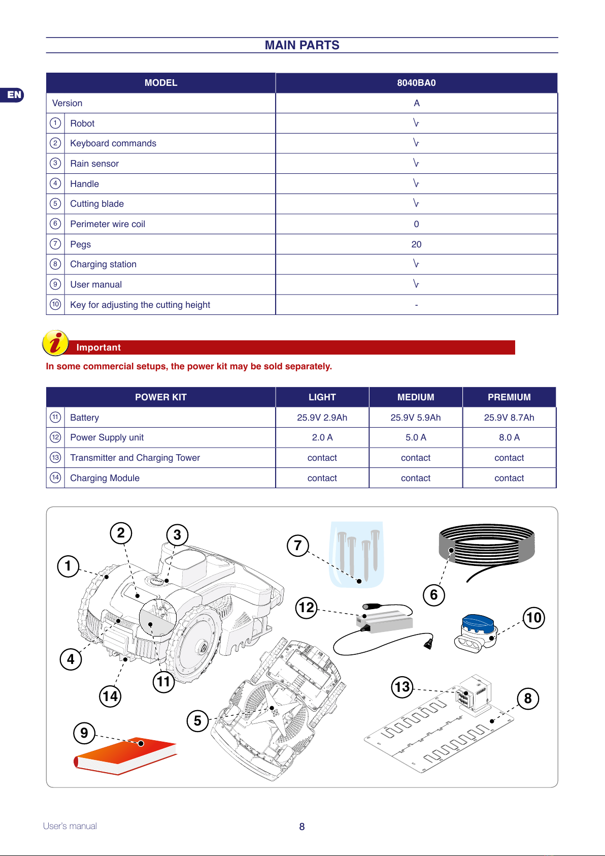
Main parts. .................................................................................................................................................................................. 8
Installation.................................................................................................................................................................................... 9
.............................................................................................................................................................. 9
Planning of system installation.................................................................................................................................................... 9
Setting up of the perimeter wire. ................................................................................................................................................11
...................................................................................................................................11
....................................................................................................... 12
.................................................................................................... 13
Installation of perimeter wire. .................................................................................................................................................... 17
........................................................................................................ 18
.................................................................................................................................................... 20
Adjustments............................................................................................................................................................................... 20
.................................................................................................................................................. 20
..................................................................................................................................................... 20
Use and operation. .................................................................................................................................................................... 21
............................................................................................................................................................... 21
...................................................................................................................... 21
Set up........................................................................................................................................................................................ 22
........................................................................................................ 23
..................................................................................................................................................... 23
..................................................................................................................... 23
Menu settings – programming mode......................................................................................................................................... 24
Robot safety stop. ..................................................................................................................................................................... 27
........................................................................................................................................... 27
............................................................................................................................... 28
Operating tips............................................................................................................................................................................ 29
Routine maintenance. ............................................................................................................................................................... 29
............................................................................................................................................... 29
.................................................................................................................................................. 29
......................................................................................................................................................................... 30
Troubleshooting. ....................................................................................................................................................................... 31
Troubleshooting guide.............................................................................................................................................................. 31
Part replacement. ...................................................................................................................................................................... 33
..................................................................................................................................... 33
................................................................................................................................................................. 33
................................................................................................................................................................... 33
Robot disposal. ......................................................................................................................................................................... 34
EC declaration of conformity.................................................................................................................................................... 35
Warranty rules. .......................................................................................................................................................................... 36
Conditions and limitations. ........................................................................................................................................................ 36
.............................................................................................................................................. 36
................................................................................................................................................................ 36
that the author is mentioned.
MD-CT-RO-16-R1.2 - EN - 10-2019

2
User’s manual
EN
GENERAL INFORMATION
PURPOSE OF THE MANUAL
•
•
•
•
•
•
•
•
Danger - Attention
This symbol indicates situations involving imminent danger, which, if ignored, could put people’s health and
safety at risk.
Warning – Caution
This symbol indicates situations where it is necessary to behave in a certain way in order to avoid putting
people’s health and safety at risk, and to protect the device.
Important

3User’s manual
EN
IDENTIFICATION OF MANUFACTURER AND EQUIPMENT
A.
B.
C.
D.
Serial Number :
Manufactured by Xxxxxxxxxxxxxxxxxx, Xxxxxxxxxxxxxxxxx
XXXXX Xxxxxxxxxxxxxxxxxxxxxxxx (XX) - XXXX
XXXXXXXXXXXXXX
MODEL TYPE MFG
(C) Manufacturing year
(C) Model
(B) EC conformity
label
(A) Name of manufacturer
(D) Technical
specifications
(C) Serial
number
DATA PLATE
(C) Version
SAFETY INFORMATION
SAFETY REGULATIONS
THIS PRODUCT COMES WITH A BLADE AND IS NOT A TOY!
•
•
•
•
Warning! Automatic lawnmower!
Keep away from the machine! Supervise children!
•
•
•
•
seriously endanger the health and safety of people.

4
User’s manual
EN
•
•
•
watertight.
•
•
•
•
•
•
•
•
•
•
SAFETY DEVICES
1. Obstacle detector
2. Inclinometer
3. Emergency stop switch
at any time during operation will immediately stop the movement of the lawnmower robot and the rotation of the blade will stop.
4. Over-current protection
the robot will stop and signal a motor error.
5. No signal sensor

5User’s manual
EN
SAFETY SIGNALS
to understand meanings before
STOP
when it is running. Wait until
the blade and rotating parts
STOP
running.
pets and other people at a safe
suitable times.
Warning! Do not spray water on
pets and other people at a safe
suitable times.
Use the robot only with the

6
User’s manual
EN
TECHNICAL INFORMATION
TECHNICAL SPECIFICATIONS
Description
Modello
8040BA0 8040BA0 8040BA0
Power KIT 2.9Ah - 2A
5.8Ah - 5A
MEDIUM
8.7Ah - 8A
PREMIUM
m2 800
1200
1800
Features
mm 635x464x300
"20 - 65
Diameter of blade 250
Motors without brushes
Cutting blade speed RPM
Ground speed Metres / Minute 30
installed.
trimmed lawn.
Ambient operating temperature Max °C
ROBOT:
CHARGING STATION:
BATTERY CHARGER:
Measured sound power level 63
IP
ROBOT
CHARGING STATION: IPx4
BATTERY CHARGER: IPx4
Mean Well
100 - 240 V~; 1.2 A;
29.4 V ; 2.0 A
Mean Well
100 - 240 V~; 2 A;
29.4 V ; 5.0 A
Mean Well
100 - 240 V~; 2.2 A;
29.4 V ; 8.0 A
25.9V 2.9Ah 25.9V 5.8Ah 25.9V 8.7Ah
Average mowing duration after a full

7User’s manual
EN
Frequencies
Transmitter for the robot driving
Bluetooth
GSM
Equipment / Accessories / Functions
4
Rain sensor Standard
Standard
Optional
station
Maximum length of perimeter wire
m 1000
GENERAL DESCRIPTION OF THE APPLIANCE
grass in gardens and house lawns at any time of the day or night.
perimeter wire.
• model of the robot and type of batteries installed;
•
•
•
RANDOM OPERATION

8
User’s manual
EN
MAIN PARTS
MODEL 8040BA0
Version A
1Robot
2
3Rain sensor
4Handle
5Cutting blade
6 0
7Pegs 20
8Charging station
9User manual
10 -
Important
In some commercial setups, the power kit may be sold separately.
POWER KIT LIGHT MEDIUM PREMIUM
11 Battery 25.9V 2.9Ah 25.9V 5.9Ah 25.9V 8.7Ah
12 Power Supply unit 2.0 A 5.0 A 8.0 A
13 Transmitter and Charging Tower
14 Charging Module
4
14
9
7
6
8
13
10
1
23
11
5
12

9User’s manual
EN
INSTALLATION
PACKING AND UNPACKING
Warning – Caution
Keep plastic wrapping and plastic containers away from infants and children: risk of suffocation!
Important
Keep the packaging materials for future use.
PLANNING OF SYSTEM INSTALLATION
•
Warning – Caution
Position the power supply unit in an area that
cannot be reached by children. For example, at a
height above 160 cm (63 ").
Warning – Caution
Make sure only authorised people have access to
the power supply.
Power supply
unit
perimeter wire
charging station
Min. height.
160 cm / 63"
transmitter
Warning – Caution
When connecting the electricity, it is necessary that a power outlet is positioned near the installation area.
Make sure the connection to the mains power complies with the applicable laws. To operate in complete
safety, make sure the electrical system, which is connected to the power supply unit, is equipped with a well-
functioning earthing system. The supply circuit shall be protected by a residual current device (RCD) with a
tripping current of not more than 30 mA.
Important
It is advisable to install the unit in a cabinet for electric components (for outdoor or indoor use), equipped
with a key lock, and well-ventilated to maintain a correct air circulation.
•
•
-on level ground;
-
-preferably in the widest part of the lawn;
-
-
-
-any metal bars or rails separating the lawn near the station may interfere with the signal. Position the station on a different
•

10
User’s manual
EN
•
•
-
-
-
the soil or humid environments;
-position it on the outside of the lawn and not inside;
-
to the power supply unit. Do not shorten or lengthen the
NO NO
OK OK
NO NO
•
OK
power supply unit
charging station
min height 160 cm
/ 63 "
min. distance
200 cm
/ 78,74 "
perimeter wire
perimeter wire
transmitter
NO

11 User’s manual
EN
SETTING UP OF THE PERIMETER WIRE
1.
2.
3.
4. Installation of the perimeter wire.
5.
track for laying the perimeter wire
RE-ENTRY METHOD TO THE CHARGING STATION
“Follow wire”
“V-Meter”
station.
step
lower 2 mt. 5 cm.
2 mt.
2 mt.
2 mt.
10 mt. 1,5 mt.
charging
station
•
•
•
“Follow wire” mode.

12
User’s manual
EN
SETUP OF THE ROBOT’S QUICK RE-ENTRY TO THE CHARGING STATION
the path and where the perimeter length is greater than 200 meters.
the perimeter wire on the opposite side.
Important
An incorrect setup of the robot’s quick re-entry may prevent the robot from returning to the charging station
quickly. When the robot travels along the perimeter to reach a secondary area, it may not detect the quick
re-entry setup.
40 40
50
1,5 mt.
step
lower
2 mt.
4-10 mt. min. 150 cm.
10 mt.
5 cm.
2 mt.
2 mt.
2 mt.
charging
station

13 User’s manual
EN
PREPARATION AND MARKING THE BOUNDARIES OF THE WORK AREAS
Preparation of the lawn to be mowed
1.
2.
The perimeter wire must be laid on the ground sloping no more
area.
Important
Areas with slopes greater than those allowed cannot
be mowed with the robot. Therefore, position the
perimeter wire in front of the slope so that it is
excluded from the area to mow.
NO
35 cm
(13,78 ")
100 cm (39,3 ")
45 cm
(17,71 ")
45 %
35 cm
(13,78 ")
21-45%
0-20%
0-20%
0-45%
0-20%
21-45%
perimeter wire
perimeter wire
OK
NO
NO
OK
OK
OK

14
User’s manual
EN
Marking the boundary of the work area
3.
perimeter wire.
The minimum passage allowed is 70 cm
edge of the perimeter wire. The perimeter wire must be
passing must be 140 cm
on both sides.
70
cm
Track for laying
the perimeter wire
min. 70 cm / 27,56 "min. 70 cm / 27,56 "
min. 70 cm / 27,56 "
corridor with a minimum passage
of 70 cm / 27,56 " from edge to edge.
PRIMARY AREA
SECONDARY AREA
70 cm
1 cm
robot.
corridor with a passage
< 70 cm / 27,56 "
PRIMARY AREA
CLOSED
AREA

15 User’s manual
EN
4.
Important
The illustration shows an example of the elements inside and on the perimeter of the work area and the
distances to follow for the correct laying of the perimeter wire. Mark the boundary of elements in iron or other
metals (drain covers, electric connections, etc.) to prevent any interferences to the signal of the perimeter
wire.
30 cm
11,81 "
30 cm
11,81 "
5 cm
1,97 "
30 cm
11,81 "
35 cm.
/13,78 "
35 cm.
/13,78 "
35 cm.
/13,78 "
35 cm.
/13,78 "
30 cm.
/11,81”
30 cm.
/11,81”
30 cm.
/11,81”
30 cm.
/11,81”
30 cm.
/11,81”
protruding roots
30 cm.
/ 11,81 “
30 cm.
/ 11,81 “

16
User’s manual
EN
paragraphs.
Important
proper functioning of the robot. Increase the distance by at least 30 cm (11.81 ") in the presence of slopes or
slippery ground.
90 cm.
/ 35,44 “
90 cm.
/ 35,44 “
90 cm.
/ 35,44 “
the robot to move regularly.
NO
min. 70 cm
/ 27,56 ”
min. 70 cm
/ 27,56 ”
< 70 cm
/ 27,56 ”
< 70 cm
/ 27,56 ”
0cm / 0 ”0 cm / 0 ”
plant
pole OKOK

17 User’s manual
EN
INSTALLATION OF PERIMETER WIRE
Important
Start laying the perimeter wire from the area where
the charging station is installed, leaving a couple of
extra meters so that it can be cut down to size when
Max.
5 cm (1,96 ")
perimeter wire
Ground wire
1.
-
-
> 70 cm (27,56 ")
35 cm
(13,78 ")
0 cm (0,0 ")
NO
wire fastening pegs
perimeter wire
radius of 20 cm
Buried wire
1.
2.
3.
4.

18
User’s manual
EN
Joining of the perimeter wire
the installation.
button on the upper side all the way down using a pair of pliers.
Important
-For a safe and secure electrical connection,
only use original joints.
-Do not use insulating tape or other types of
joints that do not provide proper isolation
(lugs, terminals, etc.). After some time, soil
moisture causes oxidation and interruption
of the perimeter wire.
3
56
4
1 2
INSTALLATION OF THE CHARGING STATION AND POWER SUPPLY UNIT
Warning – Caution
Before carrying out any operations, disconnect the
robot from the mains power.
Position the power supply unit in an area that
cannot be reached by children. For example, at a
height above 160 cm (63 ").
Do not shorten or lengthen the cable getting to the
charging station, wrap as an 8 like form the excess
The perimeter wire used for the installation cannot
be less than 50m, contact the closest customer
service centre .
protection (L)
current power supply unit (A)
transmitter (B)
H. min.
160 cm
(63.00 ")
1.
2.
3.
terminal.
The terminals are used only to connect the original perimeter wire.
protection (L) transmitter (T)
perimeter wire (M) connect to
the black terminal
connect to
the red terminal
Table of contents
Other ZCS Lawn Mower manuals