2N 9135351E User manual

Interiors, wall mounting
Outdoor spaces*, wall mounting
*) Outdoor spaces =
locations where the product is
exposed to rain or to water
running down the wall (e.g.
fence, outer wall). Mounting a
roof is obligatory in outdoor
spaces, unless the protection
against rain is provided for in
another way. Besides the roofs
presented herein, it is possible
to use roofs ref. no. 9135331E
and 9135332E
Ref. No. 9135351E
Box for wall mounting
with frame for 1 module
Size: 125 x 235 x 46 mm
Wall cut: 110 x 220 x 50 ± 5 mm
Ref. No. 9135361E
Box for wall mounting with roof
for 1 module
Roof size (width x height x depth):
129 x 240 x 41 mm
Wall cut: 110 x 220 x 50 ± 5 mm
Wall mounting
with roof
Ref. No. 9135352E
Box for wall mounting
with frame for 2 modules
Size: 225 x 235 x 46 mm
Wall cut: 210 x 220 x 50 ± 5
mm
Ref. No. 9135362E
Box for wall mounting with roof
for 2 modules
Roof size (width x height x depth):
229 x 240 x 41 mm
Wall cut: 210 x 220 x 50 ± 5 mm
Cut sizes for sets of 3 –8 modules
module count
3 m.
4 m.
5 m.
6 m.
7 m.
8 m.
Box for 2 modules, number of pieces
1
2
2
3
3
4
Box for 1 module, number of pieces
1
-
1
-
1
-
Wall, without roof, cut width, mm
335
435
560
660
785
885
Wall, with roof, cut width, mm
339
439
568
668
797
897
Gypsum plasterboard, without roof, total width of cuts, mm
330
430
555
655
780
880
Gypsum plasterboard, with roof, total width of cuts, mm
334
434
563
663
792
892
Notice: Do not fasten the boxes with plaster –they are designed for dry mounting

Mounting procedure
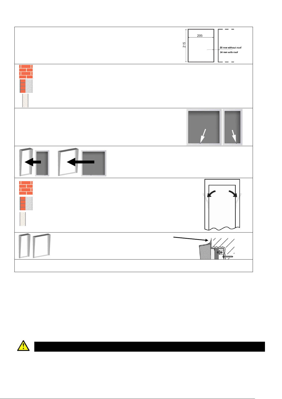
Cut a hole using the template on the reverse side of this instruction. If you work carefully
and do not exceed the tolerance of 5 mm, the frame will fully roof the edges of the cut
and there will be no need to fill it with plaster. As it is possible to cut a more perfect hole in
the plasterboard, it is advisable to make it 5 mm smaller: 105 (205) x 215 mm.
As to the plasterboard, it is advisable to cut the holes for each box like this:
Conventional wall: drill holes for wall dowels (Ø 8 mm) – use the template or directly the box. Insert the
dowels in the holes.
External insulation: Proceed as above. The dowels have to be fitted right in the wall; if the insulation
layer is thicker than 50 mm, longer screws are necessary, however, these are not a part of delivery. For
example, use 4.5 x 90 mm screws for 100 mm thick insulation.
Gypsum plasterboard: Do not use screws; the sides of the box are equipped with flippers.
Make a hole in the box to pull wires through (telephone, power supply,
electric lock etc.). When mounting more than two modules, make side holes
in the box to pull connecting cables through.
WARNING!!! This small cut (see the arrows) for the
microphone has to be on the LOWER side!!!
Only with roof:
Remove the protection sheet on the inner sides of the roof and
insert the countersink box. Then work with this unit.
Conventional wall, external insulation: insert the box (or box with roof) in
the cut in the wall and screw up. Before tightening the screws, adjust the sides
of the box vertically. We recommend to fasten the big box, ref. no. 9135352E,
with four screws ( holes in the corners of the box).
Gypsum plasterboard: Secure the box by turning the flippers (see the picture).
We recommend to protect the box from displacement with suitable glue (e.g.
silicon sealant. For plasterboard thicker than 12.5 mm, adjust the flippers or use
only glue.
Only with roof:
If you also mount the roof, seal its upper
and side edges to the wall; use silicon
sealant (see the picture).
Silicone
If the cut in the wall is not accurate and perfect, it is advisable to repair the edges with plaster.
Screws M4x10 mm attached to the bottom of the box are devised to mount Helios in the box.
Outdoor mounting rules - obligatory:
Always connect the backlight –it serves to equipment heating.
Water must not flow in along or around the cables.
Before closing the cover, carefully check all wires inside the cover for perfect closing
Remember to tighten both screws for mounting to wall
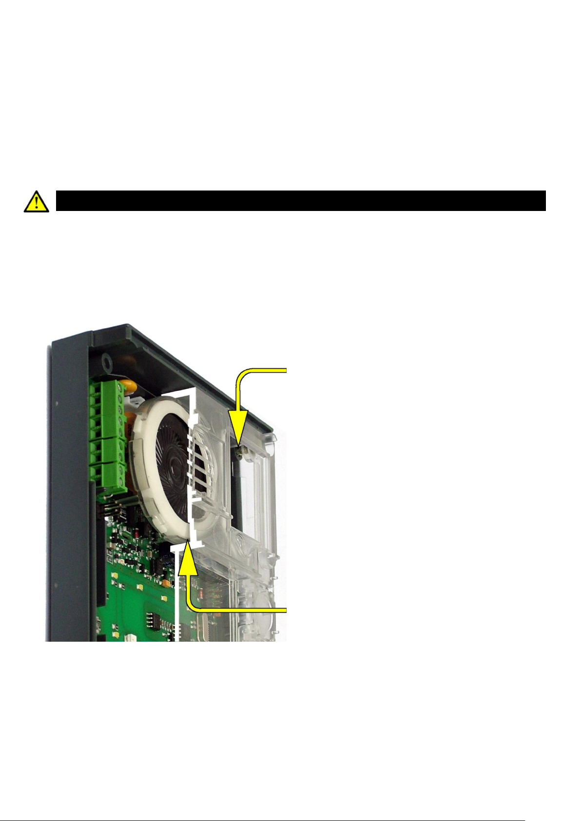
Make sure that all of the three loudspeaker holder feet fit into the board holes. A correct loudspeaker position is
necessary for a proper function of the seal.
Make sure that the silicone seal (tube on the upper face) is in place after installation.
Remember to tighten all of the four corner screws after electrical installation to make the loudspeaker seal fit
perfectly. Otherwise, water might get into the electronic part!
Caution
When the above mentioned precautions are not met, water might get in and destroy the electronics. It is
because the communicator circuits are under continuous voltage and water infiltration causes an electro-
chemical reaction. The manufacturer’s warranty shall be void for products damaged in this way!

Mounting - Completion
Remember to seal the 2N®Helios IP cable passage hole properly to avoid moisture in-leak and damage to electronics
due to condensation.
Make sure that the wires inside 2N®Helios IP are not squeezed and insert the plastic top cover (a transparent plastic mould)
carefully making its contacts plug into the electronics board connectors. Push the plastic cover into position moderately. If the part
swings over an obstacle or one corner is higher than the others, remove the cover and find the obstacle. Then tighten the corner
screws properly.
Mounting the metal cover follow the steps included in the subsection dedicated to name plate removal. Make sure that
the cover fits well and is perfectly flat. If its bottom part is loose, the mounting wall is probably uneven. Support the corners
to avoid 2N®Helios IP bending.
Caution
An improper mounting may significantly deteriorate the button function.
A poor outdoor mounting may cause water in-leak and damage to the electronics.
Most Frequent Mounting Errors
For illustration, a part of the plastic cover is removed in the figures below to reveal the sealed loudspeaker and the cover–
seal touch point. The cross section plane is marked white for better orientation.
Poorly tightened screw
(a squeezed wire has the same
effect)
WRONG
Gap between plastic cover and
loudspeaker seal
- water may leak in and damage
electronics

WRONG
Gap between plastic cover and
loudspeaker seal
- water may leak in and damage
electronics
If the loudspeaker support is in a wrong
position, the plastic cover may catch the
support brim (see the arrow) and, if
treated roughly, lead to component
deformations. Leakage may arise, see
the upper arrow.
Properly tightened screw
RIGHT
The seal touches the plastic cover. Water
flows out through a small hole (not
shown in the figure).
Note: Water does not affect the
loudspeaker Mylar membrane.
This manual suits for next models
3
Popular Enclosure manuals by other brands

Crate
Crate AIO CASE installation guide

Kingston Technology
Kingston Technology StorCase Technology Data Express DE75i-A user guide

MSI
MSI MAG VAMPIRIC 101R user guide

Zonet
Zonet ZNS8010 installation guide

Genesis
Genesis Irid 505 ARGB Quick installation guide

Lucent Technologies
Lucent Technologies J85504D-1 List 16 product manual