A.E.B. S10DP User manual
A.E.B. INDUSTRIALE s.r.l.
Via Brodolini, 8 - 40056 Crespellano (Bo) - ITALIA
Tel. + 39 051 969870 - Fax. + 39 051 969725
Internet: www.dbtechnologies.com
E-mail: [email protected]
Made in Italy
COD. 420120164 Rev. 5
digital power
RR
SS
00
ACTIVE SUBWOOFER
MANUALE d’USO - Sezione 1
USER MANUAL - Section 1
BEDIENUNGSANLEITUNG - Abschnitt 1
CARACTERISTIQUES TECHNIQUES - Section 1
ItalianoItalianoItaliano
Manuale d’usoManuale d’uso
1
ItalianoItalianoItaliano
Manuale d’usoManuale d’uso
2
220-240V~ MAX 15A
100-120V~ MAX 10A
BALANCED
MAIN INPUT
LINK
BALANCED
X-OVER
OUTPUT
+10
+4
SUB-WOOFER
LEVEL
90Hz
120Hz 0°
180°
ON SGN LIM
SUB
PHASE
SUB
XOVER
FULL RANGE MAINS INPUT
100-240V~ 50-60Hz
1250W MAX
MAINS FUSE
220-240V~ ( T5A 250V)
100-120V~ (T10A 250V)
ACTIVE P.F.C.
Made in Italy
SERIAL N.
“CAUTION”
TOPREVENT ELECTRICAL SHOCK
DONOT REMOVE COVER
“AVIS”
RISQUEDE CHOCH ELECTRIQUE
NEPAS OUVRIR
LINK
BB
dd
TECHNOLOGIESTECHNOLOGIES
digital powerdigitalpowerdigital powerdigitalpower
12
3
1= GND
2= HOT
3= COLD
12
3
12
3
SS
00
digital powerdigital powerdigital powerdigital powerdigital power
8
0dB
PUSH
SUBWOOFERDIGITAL DELAY
DD
B
d
TECHNOLOGIESTECHNOLOGIES
SS
OPTIONAL CARD
DD
ON
DATI TECNICI
Sistema Attivo
®
Tipologia amplificatore Digitale - Classe D (DIGIPRO )
Potenza RMS 1000 W
Potenza musicale 2000 W
Risposta in frequenza +/-3dB 40-150Hz
Crossover 90 - 120Hz (24dB/oct) selezionabile
Pressione sonora (SPL) 136 dB peak
Componenti 1 woofer 18” - 4” voice coil
Neodimio o Ceramico
Sensibilità ingresso nominale 0 dBu
Impedenza ingresso Bilanciato 20Kohm
Sbilanciato 10Kohm
Alimentazione Full-range con PFC, 100-240Vac, 50-60Hz
Forma diffusore rettangolare
Dimensioni [LxHxP] 515x640x720mm
Peso Neodimio 42Kg - Ceramico 48Kg
Peso (con staffe per appendibità) Neodimio 47,2Kg - Ceramico 53,2Kg
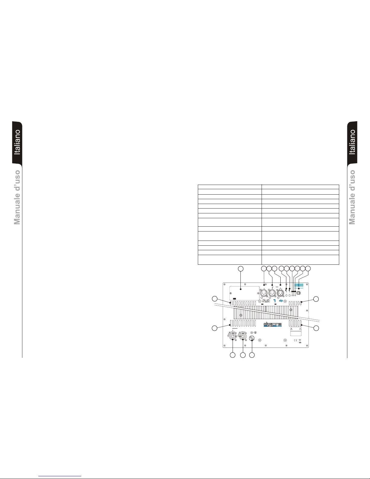
COMANDI E FUNZIONI
1) PORTA FUSIBILE “MAINS FUSE”
Alloggio per fusibile di rete.
2) PRESA DIALIMENTAZIONE “FULL RANGE MAINS INPUT”
Consente la connessione del cavo di alimentazione fornito in dotazione.
Il connettore utilizzato per il collegamento alla rete è un POWER CON® (blu)
3) PRESA DIALIMENTAZIONE RILANCIO “LINK”
Consente di rilanciare l’alimentazione di rete. L’uscita è connessa in parallelo con
l’ingresso (2) e può essere utilizzata per alimentare un altro diffusore amplificato.
Il connettore utilizzato è un POWER CON® (grigio).
4) GRIGLIE DI RAFFREDDAMENTO
Queste griglie permettono il raffreddamento dell’amplificatore durante il
funzionamento. Non ostruire gli accessi e pulire le griglie quando necessita per
garantire il corretto circolo dell’aria.
5) CONNETTORE DI INGRESSO " BALANCED MAIN INPUT”
Ingresso bilanciato a livello linea (0 dBu).
E’ in grado di accettare prese “XLR”.
6) CONNETTORE DI USCITA "LINK”
Il connettore “XLR” connesso in parallelo con l’ingresso (5) può essere utilizzato per
inviare il segnale audio in ingresso ad un altro diffusore amplificato.
7) CONNETTORE DI USCITA ”BALANCED X-OVER OUTPUT”
Uscita bilanciata del crossover interno. Il segnale prelevato da questa uscita può
essere inviato a qualsiasi diffusore amplificato.
La frequenza di taglio è selezionabile tramite il selettore “SUB X-OVER” (8).
8) SELETTORE “SUB X-OVER”
Il selettore permette di modificare l’incrocio (frequenza di taglio o crossover) tra il
subwoofer ed il diffusore ad esso collegato, tramite l’uscita “BALANCED X-OVER
OUTPUT”.
L’incrocio è settabile a 90Hz oppure 120Hz con una pendenza di 24dB/oct.
La scelta del taglio è legata dal tipo di riproduzione sonora che si vuole ottenere.
9) SELETTORE “SUB PHASE”
Il selettore permette la rotazione di 180° del segnale audio riprodotto dal subwoofer.
Tale rotazione di fase facilita l’ottimizzazione della riproduzione delle frequenze
basse anche nelle situazioni di installazioni più difficili. Completata l’installazione,
riprodurre un brano musicale ed agire sul selettore per ottenere la migliore resa
acustica delle basse frequenze
10) INDICATORE LUMINOSO “ON”
L’indicatore luminoso “ON” s’illumina di colore verde per indicare l’accensione e il
corretto funzionamento dell’amplificatore.
11) INDICATORE LUMINOSO “SGN”
Questo indicatore s'illumina di colore verde per indicare la presenza del segnale (ad
un livello di -20dB).
12) INDICATORE LUMINOSO “LIM”
Questo indicatore s’illumina di colore rosso per indicare l'intervento del circuito
limitatore interno, il quale evita la distorsione dell'amplificatore e protegge gli
altoparlanti contro sovraccarichi.
Si illumina anche all’accesione dell’amplificatore per alcuni secondi.
13) CONTROLLO SENSIBILITA’ IN INGRESSO “SUB-WOOFER LEVEL”
Questo controllo regola la sensibilità del segnale in ingresso all’amplificatore.
Tale controllo non influisce sul livello dell’uscita “LINK” e “BALANCED X-OVER
OUTPUT”
14) OPZIONE DIGITAL DELAY “SDD - SUBWOOFER DIGITAL DELAY”
Il diffusore DVA S10dp può essere equipaggiato con un circuito di delay (SDD -
SUBWOOFER DIGITAL DELAY) che permette di ritardare il segnale audio riprodotto
dal subwoofer.
5
6
7911 13
12
10
8
Questo circuito permette l’allineamento acustico tra line array e sub compensando
le diverse posizioni. Il circuito include anche una uscita bilanciata “XLR” per
rilanciare il segnale audio ritardato ad altri subwoofer; utilizzando un solo circuito di
delay è possibile ritardare contemporaneamente più subwoofer.
E’ possibile utilizzare questo circuito per la realizzazione di sistemi in configurazione
cardioidi. La configurazione cardioide permette una notevole attenuazione delle
basse frequenze emesse dalla parte posteriore dei subwoofer, mantenendo
inalterata l'emissione sonora frontale.
Tale configurazione prevede un minimo di 3 subwoofer (due con emissione frontale
e uno con emissione posteriore equipaggiato con modulo SDD).
CLASSIFICAZIONE EMI
In accordo alle normative EN 55103, l'apparato è progettato e idoneo all'utilizzo in ambienti
Elettromagnetici E3 o inferiori (E2, E1).
4
1
2
3
4
4
4
14
NEODYMIUM CERAMIC

3
EnglishEnglishEnglish
user manualuser manual
EnglishEnglishEnglish
user manualuser manual
4
CONTROLS AND FUNCTIONS
1) "MAINS FUSE" FUSE CARRIER
Mains fuse housing.
2) “FULL RANGE MAINS INPUT" POWER SOCKET
For connecting the power cable provided.
The connector used for mains connection is a POWER CON® (blue)
3) “LINK” RELAUNCH POWER SOCKET
For relaunching the mains power. The output is connected in parallel with input (2)
and can be used to power another amplified speaker.
The connector uses a POWER CON® (grey)
4) COOLING GRILLE
These grilles permit cooling the amplifier during operation.
Do not block accesses and clean the grilles whenever necessary to ensure correct
air circulation.
5) " BALANCED MAIN INPUT” INPUT CONNECTOR
Balanced input at line level (0 dBu).
It is able to accept “XLR” sockets.
6) "LINK” OUTPUT CONNECTOR
The “XLR” connector connected in parallel with input (5) can be used to send the
input audio signal to another amplified speaker.
7) ”BALANCED X-OVER OUTPUT” OUTPUT CONNECTOR
Internal crossover balanced output. The signal from this output can be sent to any
other amplified speaker.
The crossover frequency can be selected by means of the “SUB X-OVER” switch (8).
8) “SUB X-OVER” SWITCH
This switch permits selection of crossover frequency between the sub woofer and
the speakers connected to the ”BALANCED X-OVER OUTPUT” connector.
The crossing frequency is selected to 90Hz or 120Hz with a slope of 24dB/oct.
The frequency choice depends to the sound reproduction desire.
9) “SUB PHASE ” SWITCH
This switch permits 180° rotation of the audio signal reproduced by subwoofer.
Rotation makes for easier optimization of low-frequency reproduction even in the
most difficult installation situations. After completing installation, reproduce a piece
of music and adjust the switch to obtain the best low-frequency sound.
10) “ON” INDICATOR LIGHT
The “ON” indicator light comes on green to indicate the amplifier is switched on and it
is working properly.
11) “SGN” INDICATOR LIGHT
This indicator comes on green to indicate the presence of the audio signal (at a level
of -20dB).
12) “LIM” INDICATOR LIGHT
This indicator comes on red to indicate that the internal limiter circuit has tripped.
This prevents amplifier distortion and protects the speakers against overloads.
It is lights for a few seconds during the switching on.
13) “SUB WOOFER LEVEL” INPUT SENSITIVITYCONTROL
This control regulates the sensitivity of the signal at amplifier input.
This control does not affect the “LINK” and “BALANCED X-OVER OUTPUT” output
levels
14) DIGITAL DELAY “SDD - SUBWOOFER DIGITAL DELAY” OPTION
The DVA S10dp loudspeaker can be equipped with a delay module (SDD -
SUBWOOFER DIGITAL DELAY) that allows to delay the sound signal reproduced
by the subwoofer. This circuit allows sound-alignment between line array and sub
by balancing the various positions.
The circuit also includes a balanced “XLR” output that sends the delayed audio
TECHNICAL SPECIFICATION
System Active
Type of amplifier Digital - Class D (DIGIPRO )
RMS power 1000 W
Musical power 2000 W
Frequency responce +/-3dB 40-150Hz
Crossover 90 - 120Hz (24dB/oct) selecting
Sound pressure (SPL) 136dB peak
Woofer 1 x woofer 18” - 4” voice coil
Neodymium or Ceramic
Input sensitivity nominal 0 dBu
Impedance input Balanced 20Kohm
Unbalanced 10Kohm
Speaker shape rectangular
Dimension [WxHxD] 515x640x770mm
Weight Neodymium 42Kg - Ceramic 48Kg
Weight Neodymium 47,2Kg - Ceramic 53,2kg
®
Full-range with PFC, 100-240Vac, 50-60Hz
(with SRK10 Fly kit)
Power supply
signal to other subwoofers. By using a single delay module it is possible to delay
several subwoofers at the same time.
This module can also be used to create cardioid configuration systems. The cardioid
configuration provides a remarkable attenuation of the low frequencies radiated by
the rear side of the subs, without changing the direct radiated signal on the fronside.
This configuration needs at least 3 subwoofers (two with front radiation and one with
rear radiation equipped with SDD module). See appendix for more details.
EMI CLASSIFICATION
According to the standards EN 55103 this equipment is designed and suitable to operate in E3
(or lower E2, E1) Electromagnetic environments.
220-240V~ MAX 15A
100-120V~ MAX 10A
BALANCED
MAIN INPUT
LINK
BALANCED
X-OVER
OUTPUT
+10
+4
SUB-WOOFER
LEVEL
90Hz
120Hz 0°
180°
ON SGN LIM
SUB
PHASE
SUB
XOVER
FULL RANGE MAINS INPUT
100-240V~ 50-60Hz
1250W MAX
MAINS FUSE
220-240V~ ( T5A 250V)
100-120V~ (T10A 250V)
ACTIVE P.F.C.
Made in Italy
SERIAL N.
“CAUTION”
TOPREVENT ELECTRICAL SHOCK
DONOT REMOVE COVER
“AVIS”
RISQUEDE CHOCH ELECTRIQUE
NEPAS OUVRIR
LINK
BB
dd
TECHNOLOGIESTECHNOLOGIES
digital powerdigital powerdigital powerdigital power
12
3
1= GND
2= HOT
3= COLD
12
3
12
3
SS
00
digital powerdigital powerdigital powerdigital powerdigital power
8
0dB
PUSH
SUBWOOFERDIGITAL DELAY
DD
B
d
TECHNOLOGIESTECHNOLOGIES
SS
OPTIONAL CARD
DD
ON
5
6
7911 13
12
10
8
4
1
2
3
4
4
4
14
NEODYMIUM CERAMIC

DeutschDeutschDeutsch
BedienungsanleitungBedienungsanleitung
5
DeutschDeutschDeutsch
BedienungsanleitungBedienungsanleitung
6
BEDIENELEMENTE UND FUNKTIONEN
1) SICHERUNGSHALTER “MAINS FUSE”
Halter für die Netzsicherung.
2) ANSCHLUSSBUCHE “FULL RANGE MAINS INPUT”
Für denAnschluss des beiliegenden Netzkabels.
Für den Netzanschluss wird ein Stecker POWER CON® (blau) verwendet.
3) ANSCHLUSSBUCHSE DIE POWER-WEITERLEITUNG “LINK”
Sie dient zum Durchschleifen der Netzspannung. Der Ausgang ist parallel an den
Eingang (2) angeschlossen und kann zur Versorgung eines weiteren aktiven
Lautsprechers verwendet werden.
Der Steckverbinder ist eine POWER CON® Einbaubuchse(grau) .
4) LÜFTUNGSGITTER
Diese Gitter erlauben die Kühlung der Endstufe während des Betriebs. Die
Lüftungsöffnungen nicht abdecken und die Gitter nötigenfalls säubern, um die
ordnungsgemäße Luftzirkulation zu gewährleisten.
5) EINGANGSBUCHSE "BALANCED INPUT”
Symmetrischer Linepegel-Eingang (0 dBu).
Für XLR-Stecker
6) AUSGANGSBUCHSE "LINK”
Der parallel zum Eingang (5) angeschlossene XLR-Anschluss kann dazu verwendet
werden, das ankommende Audiosignal an einen anderen aktiven Lautsprecher
weiter zu leiten.
7) AUSGANGSBUCHSE ”X-OVER BALANCED OUTPUT”
Symmetrischer Ausgang der internen Frequenzweiche. Das Signal dieses
Ausgangs kann auch zu einem beliebigen sonstigen aktiven Lautsprecher
durchgeschleift werden. Die Trennfrequenz kann zwischen 90 und 120Hz mit dem
Schalter “SUB X-OVER” (8) umgeschalltet werden.
8) WAHLSCHALTER “SUB PHASE”
Mit diesem Schalter wird die Phase des S10dp Sub um 180° gedreht. Durch das
Drehen der Phase kann man die Wiedergabe der Bässe auch bei ungünstigen
akustischen Bedingungen in einfacher Weise optimieren. Nach Abschluss der
Installation ein Musikstück abspielen und ausprobieren, in welcher Schalterstellung
des Phasenschalters der Klang am besten ist.
9) WAHLSCHALTER “SUB X-OVER”
Mit diesem Schalter wird die Trennfrequenz zwischen dem S10dp Sub und den am
”BALANCED X-OVER OUTPUT” angeschlossenen Lautsprechern eingestellt. Die
Trennfrequenz kann zwischen 90 und 120Hz mit einer Flankensteilheit von
24dB/Okt. umgeschaltet werden. Die Wahl der Trennfrequenz hängt von den
akustischenAnforderrungen ab.
10) LED “ON”
Diese LED leuchtet grün, wenn das Gerät an die richtige Netzspannung
angeschlossen ist. Während des normalen Betriebes leuchtet die LED grün..
11) LED “SGN”
Diese LED leuchtet grün, wenn dasAudiosignal anliegt (mit einem Pegel von -20dB).
12) LED “LIM”
Diese rote LED leuchtet auf, um das Ansprechen des Limiters zu signalisieren,
welcher die Verzerrung des Verstärkers verhindert und die Lautsprecher gegen
Überlast schützt. Während desAnschaltens leuchtet die LED für ein paar Sekunden.
13) EMPFINDLICHKEITSREGLER EINGANG “SUBWOOFER LEVEL”
Dieser Regler dient zum Einstellen der Eingangs-Empfindlichkeit des Verstärkers.
Diese Regelung beeinflusst nicht den Ausgangspegel “BALANCED LINK” und “X-
OVER BALANCED OUTPUT”.
14) OPTION DIGITAL DELAY “SDD - SUBWOOFER DIGITAL DELAY”
Der DVA S10dp kann mit einem Delay ausgerüstet werden (SDD -SUBWOOFER
DIGITAL DELAY). Es ermöglicht die Verzögerung desTonsignal des Subwoofers.
Mit dem Delay kann man die Signallaufzeiten zwischen Line Array und Sub bei
verschiedenen Stellungen ausgleichen. Das Delay hat auch einen “XLR”- Ausgang,
um das verzögerte Signal an andere Subwoofer weiter zu senden.
Man kann dieses Modul für die Aufstellung auch von Konfigurationen
verwenden. Die Konfiguration ermöglicht eine erhebliche Dämpfung der
tiefen Frequenzen, die über die Rückseite der Subwoofer abgestrahlt werden.Die
vordere akustischeAbstrahlung bleibt dabei unverändert.
Für diese Konfiguration notwendig (zwei mit vorderer Abstrahlung
und einer mit hinterer Abstrahlung und mit SDD-Modul). Für weitere Details siehe
Anlagen.
Man kann mit
einenm einzigen Delay-Modul gleich mehrere Subwoofer gleichzeitig verzögern.
kardiode
kardiode
sind 3 Subwoofer
EMV Einstufung
Entsprechend der Norm EN 55103 ist diese Gerät entwickelt um in E3 (oder E2, E1)
elektromagnetischen Umgebungen zu arbeiten.
TECHNISCHE EIGENSCHAFTEN
System Aktiv
Verstärker typ Digital - Class D (DIGIPRO )
RMS Leistung 1000 W
Musikleistung 2000 W
Frequenzgang +/-3dB 40-150Hz
Trennfrequenz 90 - 120Hz (24dB/Okt.)
Schalldruck (SPL) 136 dB peak
Lautsprecher 1x woofer 18” - 4” voice coil
Neodymium or Ceramic
Eingangsempfindlichkeit 0 dBu
Impedanz Eingang Symmetrisch 20Kohm
Ünsymmetrisch 10Kohm
Netzspannung
Laufsprecherform rechteckig
Abmessungen [BxHxT] 515x640x770mm
Gewicht Neodymium 42Kg - Ceramic 48Kg
Gewicht (mit Flughardware) Neodymium 47,2Kg - Ceramic 53,2Kg
®
Fullrange mit PFC, 100-240V (AC), 50-60Hz
220-240V~ MAX 15A
100-120V~ MAX 10A
BALANCED
MAIN INPUT
LINK
BALANCED
X-OVER
OUTPUT
+10
+4
SUB-WOOFER
LEVEL
90Hz
120Hz 0°
180°
ON SGN LIM
SUB
PHASE
SUB
XOVER
FULL RANGE MAINS INPUT
100-240V~ 50-60Hz
1250W MAX
MAINS FUSE
220-240V~ ( T5A 250V)
100-120V~ (T10A 250V)
ACTIVE P.F.C.
Made in Italy
SERIAL N.
“CAUTION”
TOPREVENT ELECTRICAL SHOCK
DONOT REMOVE COVER
“AVIS”
RISQUEDE CHOCH ELECTRIQUE
NEPAS OUVRIR
LINK
BB
dd
TECHNOLOGIESTECHNOLOGIES
digital powerdigital powerdigital powerdigital power
12
3
1= GND
2= HOT
3= COLD
12
3
12
3
SS
00
digital powerdigital powerdigital powerdigital powerdigital power
8
0dB
PUSH
SUBWOOFERDIGITAL DELAY
DD
B
d
TECHNOLOGIESTECHNOLOGIES
SS
OPTIONAL CARD
DD
ON
5
6
7911 13
12
10
8
4
1
2
3
4
4
4
14
NEODYMIUM CERAMIC

Français
Caracteristiques techniquesCaracteristiques techniques
7
Caracteristiques techniquesCaracteristiques techniques Français
8
COMMANDES ET FONCTIONS
1) BLOC À FUSIBLE “MAINS FUSE”
Logement pour le fusible de réseau.
2) PRISE D'ALIMENTATION “FULL RANGE MAINS INPUT”
Elle permet de connecter le cordon d'alimentation fourni.
Le connecteur utilisé pour le branchement au réseau est du type POWER CON®
(bleu)
3) PRISE D'ALIMENTATION RELANCE “LINK”
Elle permet de relancer l'alimentation de réseau. La sortie est branchée en parallèle
avec l'entrée (2) et peut être utilisée pour alimenter une autre enceinte amplifiée.
Le connecteur utilisé est du type POWER CON® (gris)
4) FENTES DE REFROIDISSEMENT
Ces fentes assurent le refroidissement de l'amplificateur pendant le fonctionnement.
Ne jamais les boucher et, si cela est nécessaire, les nettoyer afin d'assurer une
ventilation efficace.
5) CONNECTEUR D'ENTRÉE “BALANCED MAIN INPUT”
Entrée symétrique au niveau ligne (0 dBu).
Elle peut accueillir des prises “XLR” .
6) CONNECTEUR DE SORTIE “LINK”
Le connecteur “XLR” connecté en parallèle avec l'entrée (5) peut être utilisé pour
envoyer le signal audio en entrée d'une autre enceinte amplifiée.
7) CONNECTEUR DE SORTIE " BALANCED X-OVER OUTPUT "
Sortie symétrique du croisement interne. Le signal prélevé de cette sortie peut être
transmis à un diffuseur amplifié quelconque. La fréquence de coupure peut être
sélectionnée à l'aide du sélecteur " SUB X-OVER" (8).
8) SÉLECTEUR " SUB X-OVER "
Ce sélecteur permet de modifier le croisement (fréquence de coupure ou crossover)
entre le caisson de grave et le diffuseur qui y est branché à travers la sortie "
BALANCED X-OVER OUTPUT ".
Le croisement peut être configuré à 90Hz ou à 120Hz avec une pente de 24dB/oct.
Le choix de la coupure dépend du type de reproduction sonore que l'on souhaite
obtenir.
9) SÉLECTEUR " SUB PHASE “
Ce sélecteur permet d'obtenir une rotation de 180° du signal audio reproduit par le
caisson de grave.
Cette rotation de phase optimise plus aisément la reproduction des fréquences
basses même lors des installations les plus difficiles. L'installation achevée,
reproduire un morceau de musique et intervenir sur le sélecteur afin d'obtenir la
meilleure performance acoustique des fréquences basses.
10) INDICATEUR LUMINEUX “ON”
L'indicateur lumineux “ON” s'allume de couleur vert pour indiquer que le diffuseur est
allumé et le fonctionnement correct de l'amplificateur.
11) INDICATEUR LUMINEUX “SGN”
Cet indicateur s'allume de couleur verte pour indiquer la présence du signal audio (à
un niveau de -20dB).
12) INDICATEUR LUMINEUX " LIM "
Cet indicateur devient rouge lorsqu'il indique l'intervention du circuit limiteur interne;
ce dernier évite la distorsion de l'amplificateur et protège les haut-parleurs des
surcharges. Il s'éclaire également pendant quelques secondes lorsque l'amplificateur
est allumé.
13) CONTRÔLE SENSIBILITÉ ENTRÉE “SUBWOOFER LEVEL”
Ce contrôle règle la sensibilité du signal en entrée à l'amplificateur. Ce contrôle
n'influence pas le niveau de la sortie “LINK” et “BALANCED X-OVER OUTPUT“.
14) OPTION DIGITAL DELAY “SDD - SUBWOOFER DIGITAL DELAY”
Le diffuseur DVA S10dp peut être équipé avec un circuit de Delay (SDD -
SUBWOOFER DIGITAL DELAY) qui permet de retarder le signal sonore reproduit
par le subwoofer.
Ce circuit permet l'alignement acoustique entre line array et sub en compensant les
diverses positions. Le circuit inclue aussi une sortie équilibrée “XLR” pour relancer le
signal sonore retardé à d'autres subwoofers; en utilisant un seul circuit de Delay il est
possible de retarder en même temps plusieurs subwoofers.
Il est possible d'utiliser ce circuit pour la réalisation de systèmes en configuration
cardioïde. La configuration cardioïde permet une importante atténuation des basses
fréquences émises par la partie postérieure du subwoofer, en maintenant intacte
l'émission sonore frontale.
Une telle configuration prévoit un minimum de 3 subwoofers (deux avec émission
frontale et un avec émission postérieure équipé d'un module SDD). Pour les détails
voir pièces jointes.
CLASSIFICATION EMI
En accord aux les normes EN 55103, l'équipement est conçu et convenable pour une utilisation en
environnement électromagnétique E3 ou inferieur (E2,E1).
CARACTÉRISTIQUE TECHNIQUES
Système Active
Typologie amplificateur Digital - Classe D (DIGIPRO )
Puissance RMS 1000 W
Puissance musicale 2000 W
+/-3dB 40-150Hz
Crossover 90 - 120Hz (24dB/oct)
Pression sonore (SPL) 136 dB peak
Composantes 1 woofer 18” - 4” voice coil
Neodymium or Ceramic
Entrée sensibilité 0 dBu
Impedance entrée Symétrique 20Kohm
Asymétrique 10Kohm
Alimentation
Forme enceinte rectangulaire
Dimensions [WxHxD] 515x640x770mm
Poids Neodymium 42Kg - Ceramic 48Kg
Poids (avec étriers) Neodymium 47,2Kg - Ceramic 53,2Kg
®
Full-range avec PFC, 100-240Vac, 50-60Hz
Réponse en fréquence
220-240V~ MAX 15A
100-120V~ MAX 10A
BALANCED
MAIN INPUT
LINK
BALANCED
X-OVER
OUTPUT
+10
+4
SUB-WOOFER
LEVEL
90Hz
120Hz 0°
180°
ON SGN LIM
SUB
PHASE
SUB
XOVER
FULL RANGE MAINS INPUT
100-240V~ 50-60Hz
1250W MAX
MAINS FUSE
220-240V~ ( T5A 250V)
100-120V~ (T10A 250V)
ACTIVE P.F.C.
Made in Italy
SERIAL N.
“CAUTION”
TOPREVENT ELECTRICAL SHOCK
DONOT REMOVE COVER
“AVIS”
RISQUEDE CHOCH ELECTRIQUE
NEPAS OUVRIR
LINK
BB
dd
TECHNOLOGIESTECHNOLOGIES
digital powerdigital powerdigital powerdigital power
12
3
1= GND
2= HOT
3= COLD
12
3
12
3
SS
00
digital powerdigital powerdigital powerdigital powerdigital power
8
0dB
PUSH
SUBWOOFERDIGITAL DELAY
DD
B
d
TECHNOLOGIESTECHNOLOGIES
SS
OPTIONAL CARD
DD
ON
5
6
7911 13
12
10
8
4
1
2
3
4
4
4
14
NEODYMIUM CERAMIC

910
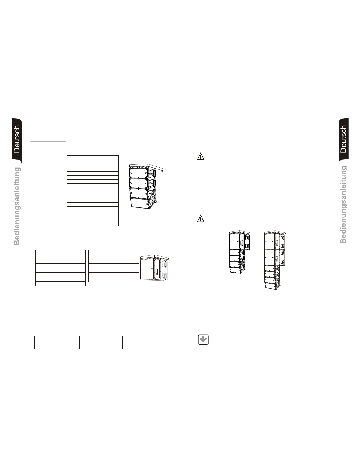
INSTALLAZIONE
Il sistema DVA ha ottenuto la certificazione TÜV per la sospensione dei diffusori
DVA T4 e DVA S10dp tramite la staffa flybar DRK 10 .
Il rapporto certifica che il peso massimo applicabile al flybar DRK10 è di 250kg.
Configurazioni con DVAT4
Il flybar DRK10 è certificato per un massimo di 16 diffusori T4
Fare riferimento alla tabella 1 per determinare il peso complessivo sopportato dal flybar
con diffusori DVAT4 in diverse configurazioni
Tabella 1 Quantità Peso
DVAT4 [kg] [lbs.]
1 15 33
2 30 66
3 45 99
4 60 132
5 75 165
6 90 198
7 105 231
8 120 264
9 135 297
10 150 330
11 165 363
12 180 396
13 195 429
14 210 462
15 225 495
16 240 528
Configurazioni con DVA S10dp
Il flybar DRK10 è certificato per un massimo di 5 diffusori DVA S10dp (woofer Neodimio) e
4 diffusori DVAS10dp (woofer Ceramico)
Fare riferimento alla tabella 2 per determinare il peso complessivo sopportato dal flybar
con diffusori DVAS10dp in diverse configurazioni
Modifiche strutturali al supporto flybar DRK10
Non possono essere eseguite modifiche senza il consenso del produttore.
Accessori originali dBTechnologies
Utilizzare solo parti originali dBTechnologies.
L’ente certificatore TÜV non ha omologato nessun altro accessorio per questo uso!
Installare sempre le parti in conformità con queste istruzioni di installazione!
Compilare e archiviare tutti i documenti del sistema DVA in un posto sicuro!
Attenzione
Nel caso in cui le suddette norme di sicurezza e il calcolo dei peso totale non siano
rispettate la dB Technologies non è responsabile di eventuali danni a cose e
persone!
Note
Durante le installazioni accertarsi che nella struttura portante del sistema vengano inclusi
nel calcolo dei pesi totali anche il peso del flybar DRK 10, delle catene dei sollevatori, dei
motori, dei cavi e ulteriori pesi aggiuntivi.
Normative di riferimento sull’uso e la manutenzione
La normativa “§ 39, VBG 9a” sull'assicurazione obbligatoria da parte datori di lavoro
Tedeschi per la prevenzione degli incidenti richiede che l'equipaggiamento del carico-
portante debba essere ispezionato da personale qualificato ed i possibili difetti debbano
essere eliminati prima della consegna all’ utente finale.
La normativa “§ 41, VBG 9a” richiede che l'equipaggiamento del carico-portante debba
essere soggetto a una manutenzione non ordinaria successivamente a danni, riparazioni
e altri incidenti che possono avere effetto sulla capacità del carico-portante.
Attenzione
Le normative sulla sicurezza possono essere diverse in funzione del paese di
destinazione. Verificare le normative valide in accordo con il regolamenti sulle
sicurezze del paese!
Quantità Peso x qtà Peso configurazione
DVA T4 8 120Kg
DVA S10dp(woofer Neodimio) 2 96Kg
Quantità Peso x qtà Peso configurazione
DVA T4 12 180Kg
DVA S10dp(woofer Neodimio) 1 48Kg
216Kg
228Kg
ItalianoItalianoItaliano
ItalianoItalianoItaliano
Manuale d’usoManuale d’uso
Manuale d’usoManuale d’uso
Configurazioni con miste con DVA T4 e DVA S10dp (woofer Neodimino)
La modularità del sistema DVA permette configurazioni sospese miste tra diffusori
DVA T4 e DVA S10dp. E’ necessario considerare che un subwoofer DVA S10dp appeso
corrisponde, in termini di peso, a circa 4 diffusori DVAT4.
Per questo motivo è necessario calcolare il carico totale nelle diverse combinazioni.
Esempio:
Quantità Peso
DVA S10dp [kg] [lbs]
(Woofer Neodimio)
1 48 106
2 96 212
3 144 317
4 192 423
5 240 528
Quantità Peso
DVA S10dp [kg] [lbs]
(Woofer Ceramico)
1 54 119
2 108 238
3 162 357
4 216 476
Tabella 2
DVA Composer - Simulazione acustica di sistemi serie DVA
DVA Composer è un software di puntamento e simulazione acustica per tutti i modelli
Line Array della serie DVA e relativi Subwoofers.
Tale software permette di gestire un sistema stereo composto da line array e subs,
simulando separatamente la risposta acustica di entrambi.
Vengono inoltre fornite all'utente una serie di informazioni quali allineamento in fase
tra i sistemi sospesi e i relativi subwoofer a terra e vengono suggeriti angoli ottimali tra
i moduli line array e relativi preset di equalizzazione, al fine di ottimizzare le
performance del sistema anche per utenti non esperti.
Si raccomanda di scaricare gratuitamente il software DVA_Composer
direttamente dal sito dB Technologies (www.dbtechnologies.com) nella
sezione dedicata «Software & Controller»
DOWNLOAD

11 12
INSTALLATION
DVA system has obtained the TÜV certification for suspension of DVA T4 and DVA
S10dp speakers through flybar stirrup DRK 10.
The report certifies that the maximum weight applying to DRK 10 flybar is 250Kg.
DVA T4 configuration
The DRK 10 flybar attests that the maximum number of DVAT4 is 16.
Refer to table 1 to determine the total weight borne by flybar according to the different
DVAT4 configurations.
Table 1 Quantity Weight
DVAT4 [kg] [lbs.]
1 15 33
2 30 66
3 45 99
4 60 132
5 75 165
6 90 198
7 105 231
8 120 264
9 135 297
10 150 330
11 165 363
12 180 396
13 195 429
14 210 462
15 225 495
16 240 528
DVA S10dp configuration
The DRK 10 flybar attests that the maximum number of DVA S10dp with Neodymium
woofer is 4 and DVA S10dp with Ceramic woofer is 5.
Refer to table 2 to determine the total weight borne by flybar according to the different
DVA S10dp configurations.
Structural modification of DRK 10 flybar
No structural modifications may be made without the manufacturer's consent.
Use only dB Technologies original parts
Original parts dB Technologies
Use only dB Technologies original parts.
The TÜV authorizing body has not certificated any other parts for use!
Always install parts in accordance with these installation instruction!
Compile and store all DVA system documents in a safe place!
Warning
If the security norms and total weight calculations are not observed, dBTechnologies
is not responsible for any possible damage to people and things.
Note
During installation ensure that carrying structure of the system has added in the total
weight also the DRK 10 flybar weight, chain hoists, motors, cables and further weights.
Initiation and Operation
The safety regulation “§ 39, VBG 9a” of the German employers' liability insurance
association's accident prevention regulations requires that load-carrying equipment be
inspected by a qualified expert and possible defects be eliminated prior to initial
commissioning by the recipient.
The safety regulation “§ 41, VBG 9a” requires that load-carrying equipment be subjected
to a non-routine inspection following damage, repair work and other incidents that can
affect load-carrying capacity.
Warning
The safety regulations might be different in other countries. Please check with your
national safety authority the valid regulations!
EnglishEnglishEnglish
EnglishEnglishEnglish
user manualuser manual
user manualuser manual
Quantity Weight x qty Configuration weight
DVA T4 12 180Kg
DVA S10dp (Neodymium woofer) 1 48Kg 228Kg
Quantity Weight x qty Configuration weight
DVA T4 8 120Kg
DVA S10dp (Neodimium woofer) 2 96Kg 216Kg
Mixed configuration with DV A T4 and DV A S10dp (Neodimium woofer)
The modular structure of DV Asystem permit s mixed suspension configuration between
DVA T4 and DVA S10dp. It is necessary to consider that one DVA S10dp hanging
subwoofer corresponds, in weight terms, to about four DVAT4 speakers.
For this reason it is necessary to calculate the total weight according to the different
configurations.
Examples:
Quantity Weight
DVA S10dp [kg] [lbs]
(Neodymium woofer)
1 48 106
2 96 212
3 144 317
4 192 423
5 240 528
Quantità Weight
DVA S10dp [kg] [lbs]
(Ceramic woofer)
1 54 119
2 108 238
3 162 357
4 216 476
Table 2
DVA Composer Acoustical Simulation and aiming for DVA Systems
DVA Composer is a 2D software for aiming and simulating acoustical response of all line
arrays and Subwoofers from DVA Series.
The software allows you to set up a stereo system composed by tops and subs, and
simulates separately the acoustical response of both.
DVA Composer also gives to the user all the information about phase alignment between
flown systems and ground stacked subwoofers, as well as it suggests an optimized
aiming of the line arrays modules and their suggested EQ presets, in order to guarantee
maximum performances even for non-expert customers.
It is recommended to download DVA_Composer free software directly from
dB Technologies (www.dbtechnologies.com) in the special section «
Software & Controller»
DOWNLOAD
14
INSTALLATION
Das DVA System erhielt die TÜV- Prüfung für DVA T4 und S10dp Lautsprecher in
Kombination mit DRK 10 Flugrahmen.
Entsprechend der Prüfung beträgt das maximal zulässige Gewicht 250 kg.
DVA T4 Konfiguration
Es dürfen maximal 16 T4 Topteile an einem DRK 10 Flugrahmen befestigt werden.
Entsprechend Tabelle 1 bestimmen sie das Gesamtgewicht und Belastung des DRK 10
Flugrahmens verschiedener DVAT4 Konfigurationen
Tabelle 1 Anzahl Gewicht
DVAT4 [kg] [lbs.]
1 15 33
2 30 66
3 45 99
4 60 132
5 75 165
6 90 198
7 105 231
8 120 264
9 135 297
10 150 330
11 165 363
12 180 396
13 195 429
14 210 462
15 225 495
16 240 528
DVA S10dp Konfigurationen
Es dürfen maximal 5 S10dp Subwoofer mit Neodimium woofer order es dürfen maximal 4
S10dp Subwooferan mit Ceramic woofer einem DRK 10 Flugrahmen befestigt werden.
Entsprechend Tabelle 2 bestimmen sie das Gesamtgewicht und Belastung des DRK 10
Flugrahmens verschiedener DVA S10dp Konfigurationen
Veränderungen an dem DRK 10 Flugrahmen
Es dürfen ohne zustimmung des Herstellers keine bauartlichen Veränderungen
vorgenommen werden.
Versenden Sie ausschließliche dBTechnologies Originalteile.
Original dB Technologies Teile
Es sind keine anderen Teile seitens des TÜV zugelassen!
Die Montage muss gemäß dieser Installations-Anleitung vorgenommen werden!
Verwahren Sie alle Dokumente des DVASystems an einen sicheren Ort!
Warnung
Werden die Sicherheitsvorschriften und die maximal zulässigen Gewichte nicht
beachtet, ist dB Technologies nicht verantwortlich für irgendwelche Schäden an
Personen oder Sachen.
Hinweis
Stellen Sie zur Installation sicher, dass die Tragevorrichtung für das Systems auch die
Gewichte des DRK 10 Flugrahmens, des Motors, des Kettenzuges, der Kabel und
anderer Gewichte tragen kann.
Inbetriebnahme und Betrieb
Nach § 39 VBG 9a müssen Lastaufnahmeeinrichtungen vor der ersten Inbetriebnahme
beim Empfänger durch einen Sachkundigen geprüft und etwaige Mängel behoben
werden.
Nach § 41 VBG 9a müssen Lastaufnahmeeinrichtungen nach Schadensfällen oder
anderen Vorkommnissen, welche die Tragfähigkeit beeinflussen können, und nach
Instandsetzungsarbeiten einer außerordentlichen Prüfung unterzogen werden.
Warnung
Sicherheits-Vorschriften kann sich je nach dem Bestimmungsland. Überprüfen
Sie die geltenden Vorschriften in Einklang mit den Vorschriften über die
Sicherheit in dem Land!
DeutschDeutschDeutsch
DeutschDeutschDeutsch
13
BedienungsanleitungBedienungsanleitung
BedienungsanleitungBedienungsanleitung
Anzahl Gewicht x Anzahl Konfigurationen Gewicht
DVA T4 12 180Kg
DVA S10dp(Neodymium woofer) 1 48Kg 228Kg
Anzahl Gewicht x Anzahl Konfigurationen Gewicht
DVA T4 8 120Kg
DVA S10dp(Neodimium woofer) 2 96Kg 216Kg
Gemischte Konfigurationen mit DVA T4 und DVA S10dp
Die mechanische Konstruktion des DVA Systems erlaubt eine gemischte Konfiguration
zwischen DVA T4 und DVA S10dp. Es ist wichtig zu beachten, dass ein geflogener DVA
S10dp Subwoofer dem Gewicht von vier über DVAT4 entspricht. Aus diesem Grund ist es
notwendig, das Gesamtgewicht entsprechend der unterschiedlichen Konfigurationen zu
bestimmen.
Beispiele:
Anzahl Gewicht
DVA S10dp [kg] [lbs]
(Neodymium woofer)
1 48 106
2 96 212
3 144 317
4 192 423
5 240 528
Anzanhl Gewicht
DVA S10dp [kg] [lbs]
(Ceramic woofer)
1 54 119
2 108 238
3 162 357
4 216 476
Tabelle 2
DVA Composer Akustiksimulation für Systeme der Serie DVA
DVA Composer ist eine Software zur Beschallungsplanung und simulation für alle Line
Array-Modelle der Serie DVA und den zugehörigen Subwoofern.
Sie ermöglicht die Verwaltung eines Stereosystems, das aus LineArrays und Subwoofern
besteht, wobei das akustischeAnsprechprofil jeweils separat simuliert wird.
Dem Nutzer werden eine Reihe von Daten geliefert, z.B. die Phasenanpassung zwischen
den Hängesystemen und den entsprechenden Subwoofern am Boden. Außerdem
werden die optimalen Winkel zwischen den LineArray-Modulen und den entsprechenden
Equalizer-Presets angegeben, so dass auch weniger erfahrene Benutzer die Leistungen
des Systems optimieren können.
Wir empfehlen, die Software DVA_Composer direkt von der Webseite dB
Technologies (www.dbtechnologies.com) im Abschnitt «software &
Controller» herunterzuladen
DOWNLOAD

15 16
INSTALLATION
Le système DVA a obtenu la certification TÜV pour la suspension des diffuseurs
DVA T4 et DVA S10dp grâce à l'étrier flybar DRK 10 .
Le rapport certifie que le poids maximum applicable au flybar DRK10 est de 250kg.
Configurations avec DVAT4
Le flybar DRK10 est certifié pour un maximum de 16 diffuseurs T4
Consulter le tableau 1 afin de déterminer le poids compressif supporté par le flybar avec
diffuseurs DVAT4 dans différentes configurations.
Tableau 1 Quantité Poids
DVAT4 [kg] [lbs.]
1 15 33
2 30 66
3 45 99
4 60 132
5 75 165
6 90 198
7 105 231
8 120 264
9 135 297
10 150 330
11 165 363
12 180 396
13 195 429
14 210 462
15 225 495
16 240 528
Configurations avec DVA S10dp
Le flybar DRK10 est certifié pour un maximum de 5 diffuseurs DVA S10dp avec
Neodymium woofer ou pour un maximum de 4 diffuseurs DVA S10dp avec Ceramic
woofer. Consulter le tableau 2 afin de déterminer le poids compressif supporté par le
flybar avec diffuseurs DVAS10dp dans différentes configurations.
Modifications de structure sur le support flybar DRK10
Aucune modification ne peut être faite sans l'accord du producteur.
Accessoires originaux dBTechnologies
N'utiliser exclusivement que des pièces originales dBTechnologies.
L'organisme de certification TÜV n'a homologué aucun autre accessoire prévu pour cet
effet!
Installer toujours les parties en conformité avec ces instructions d'installation!
Remplir et mettre aux archives tous les documents du système DVA dans un lieu sûr !
Attention
Dans le cas où lesdites mesures de sécurité et de calcul de poids total ne sont pas
respectées, dB Technologies n'est en aucun cas responsable des éventuels
dommages provoqués aux objets et aux personnes!
Notes
Durant les installations, bien s'assurer que dans la structure portante du système soient
inclus dans le calcul des poids totaux ainsi que le poids du flybar DRK 10, des chaînes des
élévateurs, des moteurs, des câbles et autres poids ajoutés.
Début et fonctionnement
La norme sur la sécurité “§ 39, VBG 9a” sur l'assurance obligatoire de la part des
employeurs allemands pour la prévention des accidents demande que l'équipement du
porte-charge doit être inspecté par un personnel qualifié et que les possibles défauts
doivent être éliminés avant la livraison à l'usager final.
La norme sur la sécurité “§ 41, VBG 9a” demande que l'équipement du porte-charge doit
être sujet à une manutention non ordinaire suite à des dommages, réparations et autres
incidents qui peuvent avoir effet sur la capacité du porte charge.
Attention
Les normes sur la sécurité peuvent être différentes en fonction du pays de
destination. Vérifier les normes en rigueur en accord avec les règlements sur les
sécurités du pays!
Français
Caracteristiques techniquesCaracteristiques techniques
Caracteristiques techniquesCaracteristiques techniques Français
Quantité Poids par quantité Poids configuration
DVA T4 12 180Kg
DVA S10dp(Neodymium woofer) 1 48Kg 228Kg
Quantité Poids par quantité Poids configuration
DVA T4 8 120Kg
DVA S10dp(Neodimium woofer) 2 96Kg 216Kg
Configurations avec mélange DVA T4 et DVA S10dp (Neodimium woofer)
La modularité du système DVA permet des configurations suspendues mixtes entre les
diffuseurs DVA T4 et DVA S10dp. Il est nécessaire de considérer qu'un subwoofer DVA
S10dp suspendu correspond, en terme de poids, plus ou moins à 4 diffuseurs DVAT4.
C'est pour ce motif qu'il est nécessaire de calculer la charge totale dans les différentes
combinaisons.
Exemple:
Quantité Poids
DVA S10dp [kg] [lbs]
(Neodymium woofer)
1 48 106
2 96 212
3 144 317
4 192 423
5 240 528
Quantité Poids
DVA S10dp [kg] [lbs]
(Ceramic woofer)
1 54 119
2 108 238
3 162 357
4 216 476
Tableau 2
DVA Composer Simulation acoustique de systèmes de séries DVA
DVA Composer est un logiciel de direction et simulation acoustique pour tous les
modèles de lignes de source de la série DVA et les caissons de basse relatifs.
Ce logiciel permet de gérer un système stéréo composé de ligne source et de
caissons de basse, simulant séparément la réponse acoustique de chacun des deux.
De plus, de nombreuses informations sont fournies à l'utilisateur, comme l'alignement
en phase entre les systèmes suspendus et les relatifs caissons de basse à terre, ou la
syggestion d'angles optimisés entre les modules de ligne de source et les préréglages
d'égaliseur relatifs. Cela permet d'optimiser les performances du système, même pour
des utilisateurs non experts.
On conseille de télécharger gratuitement le logiciel DVA_Composer
directement à partir du site dB Technologies (www.dbtechnologies.com)
dans la section dédiée « Software & Controller »
DOWNLOAD

17 18
BALANCED
INPUT
BALANCED
LINK / OUT
1 = GND
2 = HOT
3 = COLD
PUSH
Digital Vertical Array
T
4
MIXER
FULL RANGE
OUTPUT
BALANCED
INPUT
BALANCED
LINK / OUT
1 = GND
2 = HOT
3 = COLD
PUSH
Digital Vertical Array
T
4
BALANCED
INPUT
BALANCED
LINK / OUT
1 = GND
2 = HOT
3 = COLD
PUSH
Digital Vertical Array
T
4
BALANCED
INPUT
BALANCED
LINK / OUT
1 = GND
2 = HOT
3 = COLD
PUSH
Digital Vertical Array
T
4
COLLEGAMENTI
CABLE CONNECTIONS
VERKABELUNG
CABLAGE
SCHEMA A BLOCCHI
BLOCK DIAGRAM
BLOCKSCHALTBILD
DIAGRAMA EM BLOQURES
BALANCED
MAIN INPUT
LINK
BALANCED
X-OVER
OUTPUT
90Hz
120Hz
SUB
X-OVER
switch
Digital Delay
Optional
WOOFER 18”
LIMITER
SUB
PHASE
switch
Phase
180°
Phase
0°
SIGNAL
-20dB
CONTROL CIRCUITS
L
N
MAINS INPUT MAINS
FUSE
INPUT
SENS
READY
L
N
MAINS INPUT
LINK
BALANCED
MAIN INPUT
LINK
BALANCED
X-OVER
OUTPUT
12
3
1 = GND
2 = HOT
3 = COLD
12
3
12
3
S
0
PUSH
Switching Mode
Power Supply
PFC
Power Factor
Correction
SMPS
Class D
®
DIGIPRO
Class D

19 20
INSTALLAZIONE
INSTALLATION
INSTALLATIONEN
INSTALLATIONS
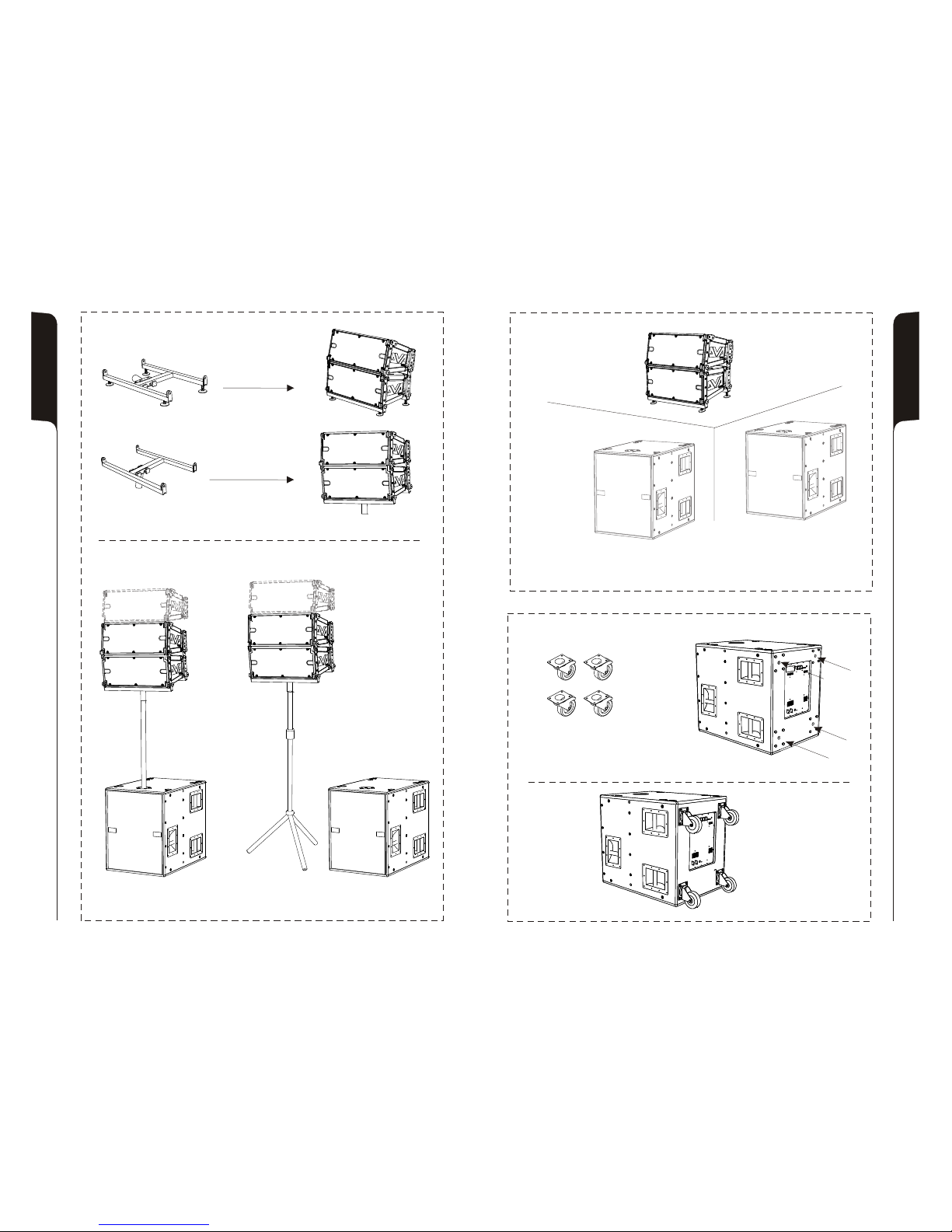
In appoggio - impilato
Groundstack - stacked
In appoggio
Groundstack
In appoggio con flybar (opzione DRK 10)
Groundstack with flybar (DRK 10 option)
22
21
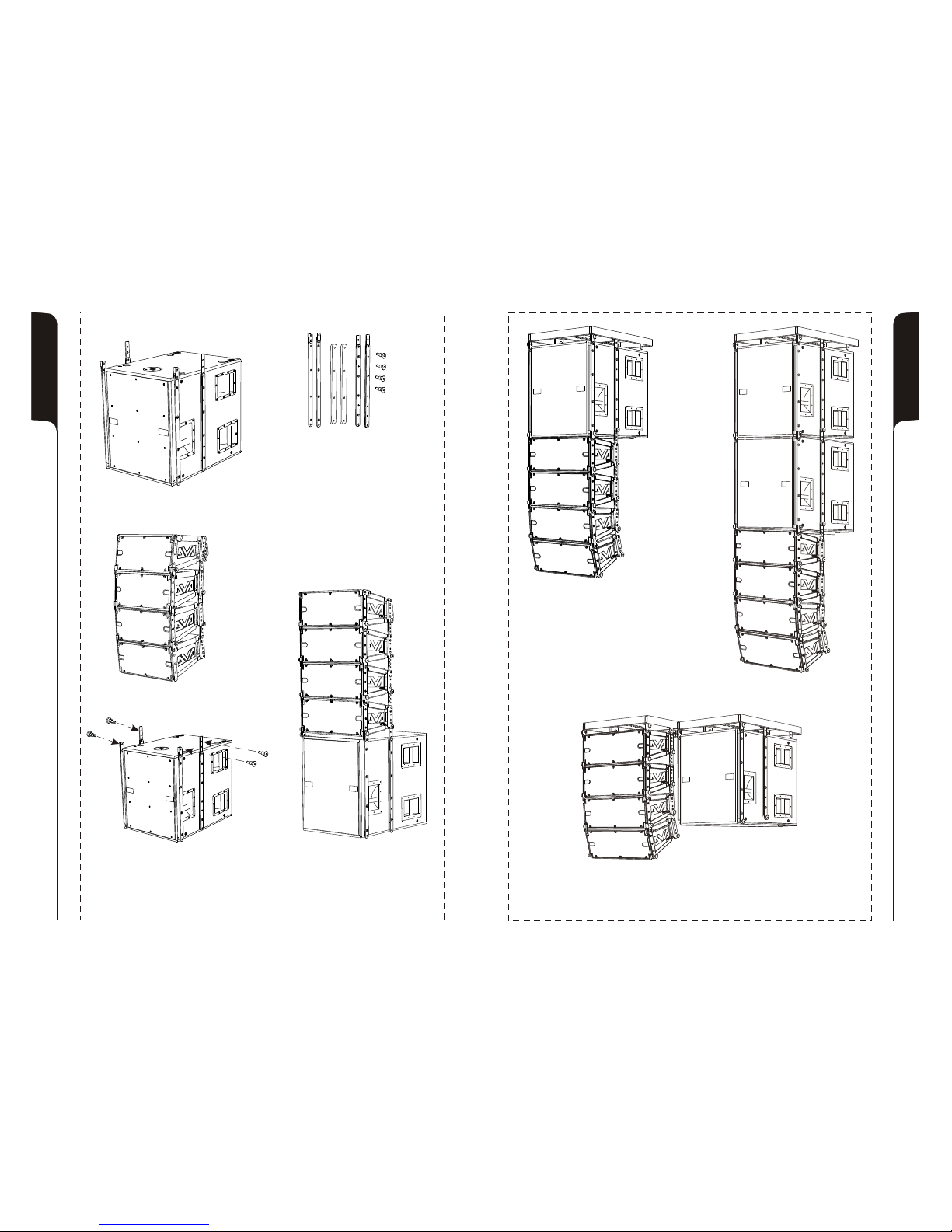
Appeso con kit staffe (opzione SRK-10) e flybar (opzione DRK-10)
Hang with stirrups kit (SRK-10 option) and flybar (DRK-10 option)
Kit staffe- opzione SRK 10
Kit stirrups - SRK-10 option
In appoggio con kit staffe
Groundstack with kit stirrups
23 24
In appoggio son supporto su asta
per Groundstack with stand adaptor
Set di 4 ruote - opzione DWK 20
Set of 4 wheels - DWK 20 option
In appoggio a pavimento con supporto asta provvisto di piedi
Groundstack to floor with stand adaptor with feet
Per supporto asta
Stand adaptor
Opzione DSA 4
DSA 4 Option
In appoggio
Floor stack

25
Digital Delay subwoofer - opzione SDD
Subwoofer Digital Delay - SDD option
GAP
mSec
DELAY SET-UP
.0 .5
.4
.3
.1 .2
.6
.7
.8
.9
05
4
3
12
6
7
8
9
050
40
30
1020
60
70
80
90
- - -
.
ALLINEAMENTO SEGNALE AUDIO
ALIGNAMENT AUDIO SIGNAL
CONFIGURAZIONE CARDIOIDE
CARDIOID CONFIGURATION
26
Delay setup = (GAP X 1000) / 344
Delay = ms (specify milliseconds)
GAP = m (specify meters)
Sound speed = 344 m/s
Ruotare la fase di 180°
Rotate 180° phase
SUB
PHASE
0°
180°
Impostare il delay a 4,5msec
Set delay to 4,5msec
mSec
DELAY SET-UP
.0 .5
.4
.3
.1 .2
.6
.7
.8
.9
05
4
3
12
6
7
8
9
050
40
30
1020
60
70
80
90
- - -
.
Delay = ms (espresso in millisecondi)
GAP = m (espresso in metri)
Velocità suono = 344 m/s
BALANCED
MAIN INPUT
LINK
BALANCED
X-OVER
OUTPUT
+10
+4
SUB-WOOFER
LEVEL
90Hz
120Hz 0°
180°
ON SGN LIM
SUB
PHASE
SUB
XOVER
BB
dd
TECHNOLOGIESTECHNOLOGIES
12
3
1= GND
2= HOT
3= COLD
12
3
12
3
SS
00
8
0dB
PUSH
BALANCED
MAININPUT
LINK
BALANCED
X-OVER
OUTPUT
+10
+4
SUB-WOOFER
LEVEL
90Hz
120Hz 0°
180°
ON SGNLIM
SUB
PHASE
SUB
XOVER
B
d
TECHNOLOGIES
12
3
1= GND
2= HOT
3= COLD
12
3
12
3
SS
00
8
0dB
PUSH
PUSH
NEODYMIUM CERAMIC
Table of contents
Languages:
Other A.E.B. Subwoofer manuals


