ABONG SEBRINGVILLE 3157826 User manual

A clock is a precision mechanical instrument containing many
slowly moving parts. ere are over a hundred points of contact
where friction works to bring it to a stop.
Take your time assembling this kit, and pay attention to the
details. Great pains have been taken to cra these instructions
to ensure your success. If there are any steps that seem unclear,
please let us know.
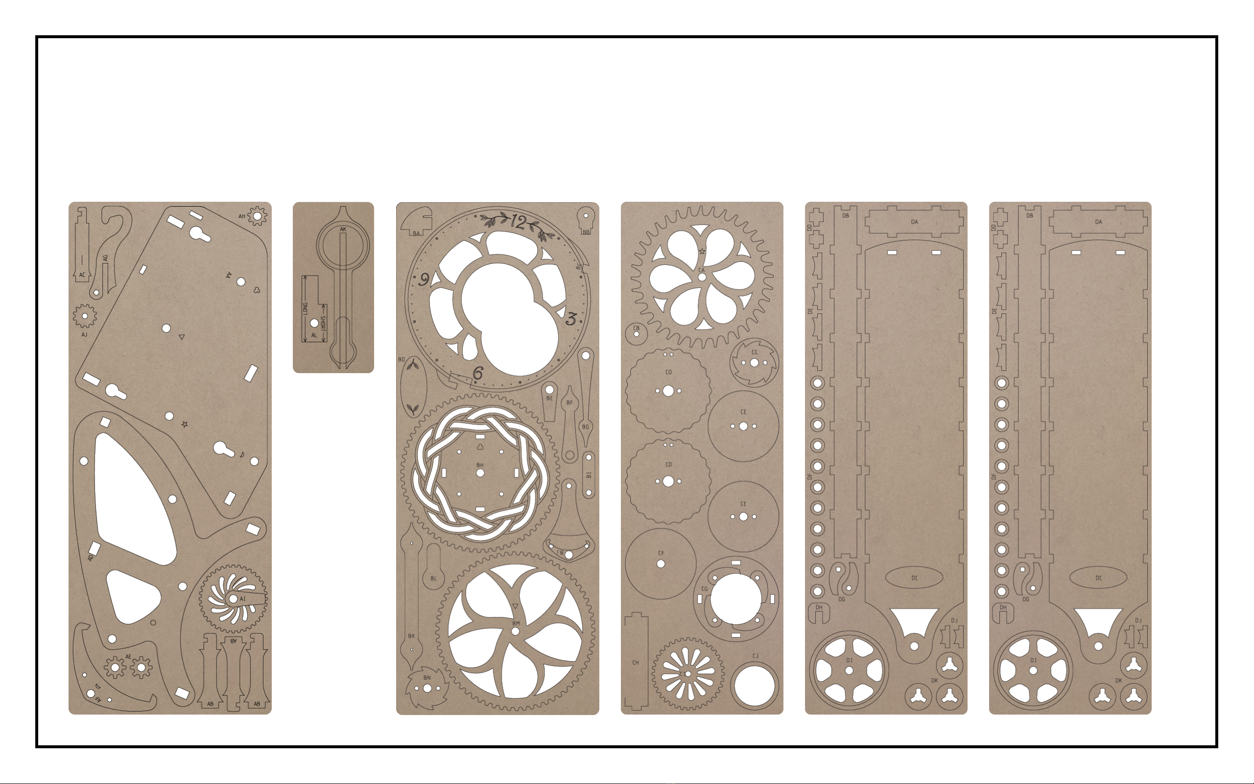
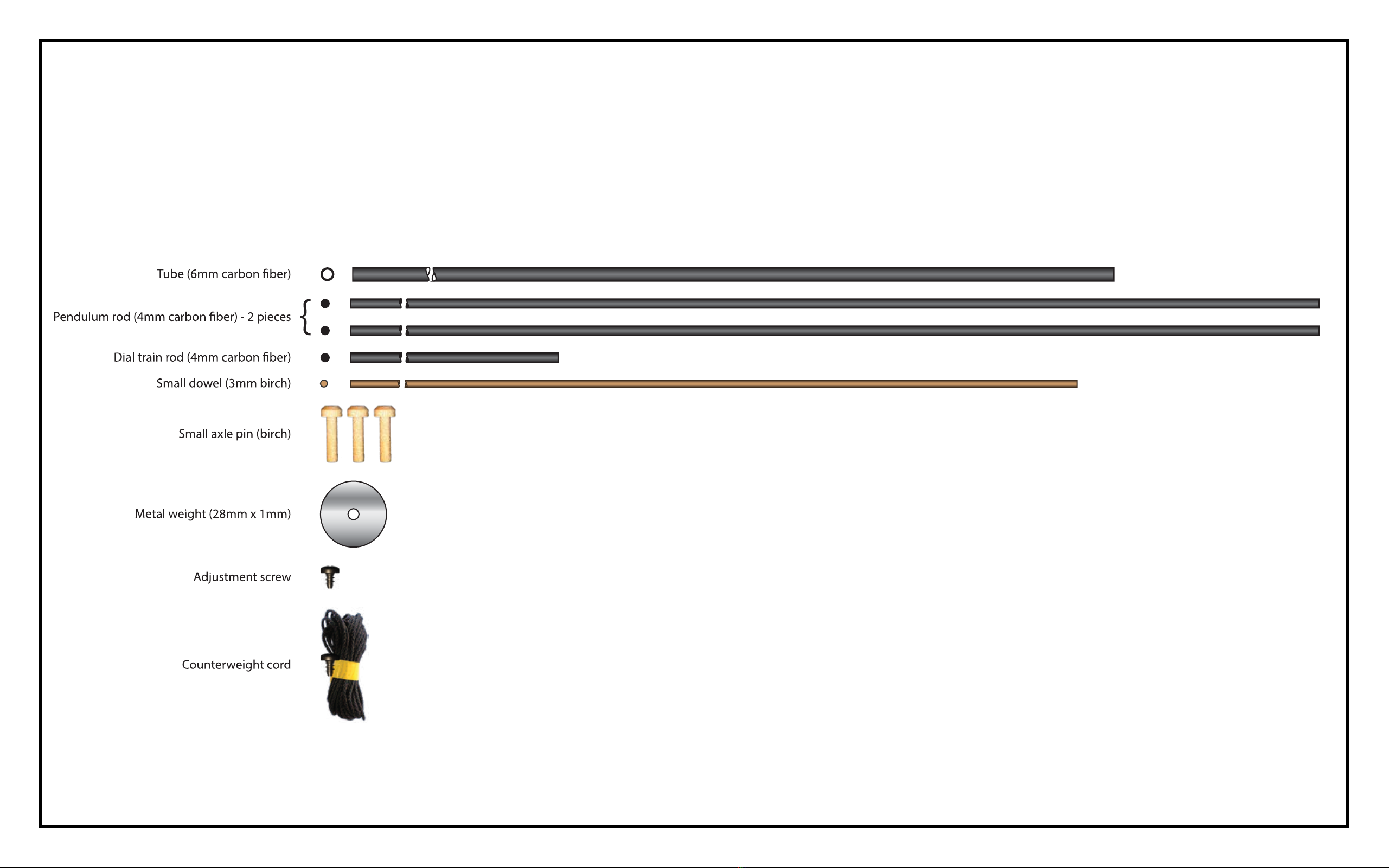
Before you begin, check that there are no missing or damaged
pieces in the kit. A parts list is provided to help identify each
piece.
Finally, read through all the instructions before you begin. is
will help you understand how each piece ts into the nished
clock.
WALL CLOCK KIT
SEBRINGVILLE
DAMAGED OR MISSING PARTS?
email: service@abong.com
Made in Canada by
ABONG, Inc
5-775 Woodlawn Road W
Guelph, ON N1K 1Y7
WARNING!
CHOKING HAZARD - CONTAINS
SMALL PARTS. NOT RECOMMENDED
FOR CHILDREN UNDER 3 YEARS

1. Six laser cut sheets are supplied with the kit.
• There are two thicker boards, one large and one small with parts labels beginning with ‘A’
• There is one thinner board with parts labels beginning with ‘B’
• There is one thinner board with parts labels beginning with ‘C’
• There are two identical thinner boards with parts labels beginning with ‘D’

2. The kit also contains a number of other components
needed to complete the clock.

3. The tools needed to assemble this kit are:
• Razor saw (42 teeth per inch)
• Scissors

The supplies needed to complete the kit are:
• Two or three sheets of good quality, ne grit (220) sandpaper
• Cyanoacrylate gel glue (also called “CA”, crazy, or super glue).
• Wood glue (also called carpenter’s or PVA glue)
• One pack (6000 count) BBs (Daisy or Crosman)
• Block of scrap wood (optional)

AFTER
BEFORE
4. Using 220 grit sandpaper, sand both faces of each part to
remove blemishes and residue left by the laser cutting
process. For large pieces, use a sanding block, which can
be as simple as a piece of scrap wood with sandpaper
wrapped around it.

5. For small pieces, lay the sandpaper at and move the
part against it. Take care not to remove any laser etched
marks. Taking a little extra care and patience to prepare
each piece will make a huge impact on the appearance of
the completed kit.

6. To sand holes and smaller openings, tear a small strip
of sandpaper and tightly roll it into a cone shape small
enough to t. Work the sandpaper into the opening,
twirling it as it is moved in and out.

7. To sand gear teeth, fold a strip of sandpaper twice, and
sand each tooth across the thickness of the material.
Work around the rim of the gear rst working on one side
of each tooth, then ip the gear over, and sand the other
side.
Take care to remove only enough material to expose the
natural color of the material.

8. The dark edge left by the laser cutting process is caused
by natural resins in the material. It does not bond well
with glue.
The instructions will include diagrams indicating which
edges need to be sanded.
Lightly sand the highlighted edges to expose the material
beneath. Don’t forget that holes need to be sanded too!

9. Before applying glue, always test the t of the parts.
Carefully sand any joints that bind so the parts t together
smoothly.
Sand the end of alignment pins, rods, and tubes to remove
any rough edges.
It is critical that the parts are fully inserted, and all edges
are in contact to ensure correct operation of the nished
clock.

10. Wood glue (also known as carpenter’s glue or PVA) is used
to “tack” parts together. It takes longer to dry and allows
the parts to be adjusted before the glue sets and hardens.
The symbol below indicates wood glue is required in a
step

11. CA glue (also known as cyanoacrylate glue, crazy glue or super glue) is used to
permanently bond parts together. It is available as a liquid or gel. The gel type is
preferable for this application as it stays where applied.
This glue will “sieze” the parts as soon as you stop moving them.
First test t the parts, then apply glue to one part before attaching the other part
in one smooth steady motion. Remove any excess with a damp paper towel
before it sets.
Carefully follow the safety instructions provided with the glue you use!
The symbol below indicates CA glue is required in a step

12. Carbon ber is tough and can be challenging to cut.
Always use a sharp blade and follow these steps to get the
best results.
Secure the piece to be cut. Some options are:
• a miterbox
• a vice
• a block of scrap wood

13. Wrap the area to be cut with masking tape. 14. Measure and mark the masking tape where the part
will be cut.
15. Lightly draw the saw over the part to score it on the
marked line. This will help prevent the blade from
wandering.
16. Apply very light downward force to the saw as you
cut. Excessive pressure will dull the teeth and clog
the saw.
17. Reduce the amount of pressure applied even
more near the end of the cut to avoid fraying or
delaminating the carbon ber.
18. Sand the cut edge to remove any burrs.

19. If you wish to apply a nish to the kit, craft paints are a
simple and effective method. Carefully apply the paint
to completed components before nal assembly. Avoid
getting nish onto any edge or surface that will be glued
or or contact other parts while the clock is running..

1. Use the guide (AL) as a reference to cut four ‘LONG’ sections of carbon ber
tube. Ensure the ends are cut at, and the length is accurate.
Use a sharp razor saw, jig saw, or dremel tool.
Wear a mask and safety glasses.

2. Use the guide (AL) as a reference to cut three ‘SHORT’ sections from the
remaining carbon ber tube.
Use a sharp razor saw, jig saw, or dremel tool.
Wear a mask and safety glasses.
There will be a length of tube left over. Set it aside as a spare.

3. Use the guide (AL) as a reference to cut eight ‘SHORT’ sections from the
small dowel. These are alignment pins.
Use a sharp razor saw, jig saw, or dremel tool.
Wear a mask and safety glasses.
There will be a length of dowel left over. Set it aside as a spare.

4. Insert a ‘LONG’ section of tube into the guide (AL).
Do not glue! 5. Slip on an end plate (DK) . Do not glue!
6. Use CA glue to attach three long spacers (DE) to the
end plate.
Do not get glue on the tube!
7. Use CA glue to attach an end plate (DK) to the long
spacers (DE). The long spacers (DE) must be fully
inserted into the end plate (DK).
Do not get glue on the tube!
8. Use CA glue to attach a spacer ring (DF) to the top end
plate (DK).
Do not get glue on the tube! 9. Remove the long spacer assembly from the tube.