Abstract Data ADE-60 User manual

ADE-60 4:4 MIX UTILITY
Cascading, 4-Channel, Mix & CV Utility with user-configurable
options for 2x Gain, Attenuversion, Biasing & CV.

INTRODUCTION:
1) Module Overview Main module features in brief
2) Front Panel Front panel layout and controls
3) Rear Connections Power, connectivity and precautions
4) Quick Start Your first patch
OPERATION:
5) Inputs & Outputs Explanation of all sockets
6) Knobs Explanation of knob functions
FEATURES:
7) Operation Mixer configuration examples
SPECIFICATIONS:
8) Specs Hardware and spec overview
© 2016 Abstract Data Ltd. Version 1.1 May 2016
Contents

• The ADE-60 is a highly-configurable mixing and Control Voltage (CV) utility.
• Each channel gives options for 2x Gain, Attenuversion and CV/Biasing which can be configured via
3 rear panel connectors allowing users to create a configuration that suits their own requirements.
• The mixer can be used in any combination from a standard 4-input/1-output summing mixer to
4 individual 1-input/1-output Attenuators or stand-alone CV sources.
• Plugging a cable into any of the output sockets removes any of the previous signal inputs from the
mix at the outputs that follow it.
• Used in conjunction with the Gain and Attenuversion settings - the CV/Biasing option can provide
CV in the following ranges on any and/or all Outputs: 0-5V; 0-10V; +/-5V; +/-10V.
• The module is supplied with 2 sets of knobs - 4 Grey and 4 Blue to allow the user to denote different
combinations of functionality.
• The ADE-60 is capable of outputting both CV signals and high-gain audio signals - please take care
not to damage speakers, headphones - or ears! - with configurations that deal with these signal types.
• The ADE-60 has reverse-voltage protection built in - but please pay attention to the power supply
and connection guidelines on Page 3 of this manual.
© 2017 Abstract Data Ltd. Version 1.0 October 2017
1: Module Overview
Page 1 of 8

Page 2 of 8
VOLUME: 1 Sets the volume and the level of user-defined functions for channel 1
IN: 1 Signal input for channel 1
OUT: 1 Signal output for channel 1
VOLUME: 2 Sets the volume and the level of user-defined functions for channel 2
IN: 2 Signal input for channel 2
OUT: 2 Signal output for channel 2 or mix output of previous unpatched channels
VOLUME: 3 Sets the volume and the level of user-defined functions for channel 3
IN: 3 Signal input for channel 3
OUT: 3 Signal output for channel 3 or mix output of previous unpatched channels
VOLUME: 4 Sets the volume and the level of user-defined functions for channel 4
IN: 4 Signal input for channel 4
OUT: 4 Signal output for channel 4 or mix output of previous unpatched channels
© 2017 Abstract Data Ltd. Version 1.0 October 2017
2: Front Panel

Page 3 of 8
POWER CONNECTION: 10-16 pin Eurorack power connection
CHANNEL 1 USER CONFIG: Attenuversion Gain Biasing settings for channel 1
CHANNEL 2 USER CONFIG: Attenuversion Gain Biasing settings for channel 2
CHANNEL 3 USER CONFIG: Attenuversion Gain Biasing settings for channel 3
CHANNEL 4 USER CONFIG: Attenuversion Gain Biasing settings for channel 4
© 2017 Abstract Data Ltd. Version 1.0 October 2017
3: Rear Connections
RED STRIPE
POWER CABLE
PRECAUTIONS: Only connect the power cable to the power connection as shown.
DO NOT CONNECT THE POWER CABLE TO ANY OTHER PORT!
The ADE-60 uses the Doepfer standard for power connection and cable orientation.
The RED stripe on the supplied power cable connects to the NEGATIVE (-12V) rail
on the ADE-60 with the RED stripe facing DOWN. This is marked on the back of
the ADE-60 PCB as “– RED”.
The ADE-60 has diode and polyfuse protection built in but an incorrectly connected
cable may still cause permanent damage to the module or the power supply.
The rear panel of the ADE-60 has exposed parts and connections. Please ensure
when handling the ADE-60 that the unit is held by the sides of the front panel or
the sides of the Printed Circuit Board (PCB).
-RED

1) USER CONFIGURATION
Make sure all 12x black plastic jumper jonnectors are in place on the rear Printed Circuit Board (PCB)
on the left hand pair of the 3x pin headers.
2) INPUTS
Turn all 4x knobs fully counter-clockwise.
Connect an audio signal to IN:1
3) OUTPUTS
Connect the output of channel 4 to a suitable audio monitoring source.
Turn the VOLUME:1 knob clockwise to increase the volume of the signal at IN:1 to unity gain
(at fully clockwise).
The audio signal at IN:1 is available at OUT:1-4.
Connecting a patch cable to OUT:1 will remove the signal at IN:1 from OUT:2-4.
Connecting a patch cable to OUT:2 will remove the signal at IN:1 from OUT:3-4.
© 2017 Abstract Data Ltd. Version 1.0 October 2017
4: Quick Start
Page 4 of 8

1) IN:1-4
The ADE-60 has 4 inputs - one for each of the four mixer channels.
An input at any channel will cascade to all of the following channels - until those signals hit an output
socket that is patched.
This cascading design allows for any configuration from 1x 4-input mixer with a single output to 4x
individual 1-input/1-output attenuators or any combination in between.
2) OUT:1-4
The ADE-60 has 4 outputs - one for each of the four mixer channels.
An output socket that is patched will output the summed signal from all previous channels with
patched inputs and unpatched outputs.
© 2017 Abstract Data Ltd. Version 1.0 October 2017
5: Inputs & Outputs
Page 5 of 8

1) VOLUME:1-4
Provides manual control over the attenuation of the input signal at the corresponding input.
When any of the 3 user-configurable settings are implemented this knob will also provide manual
control over Gain, Attenuversion and CV/Biasing levels.
© 2017 Abstract Data Ltd. Version 1.0 October 2017
6: Knobs
Page 6 of 8

1.1) 4-Input / 1-Output Mixer
2.1) 2x 2-Input / 1-Output Mixers
3.1) 4x 1-Input / 1-Output Attenuators
1.2) 4-Input + CV Bias / 1-Output
2.2) 2x 2-Input + Gain/Inversion / 1-Output Mixers
3.2) 4x CV Sources
© 2017 Abstract Data Ltd. Version 1.0 October 2017
7: Operation
Page 7 of 8
Input 1.1 >[IN:1]
[OUT:1]
[IN:2]
[OUT:2]
[IN:3]
[OUT:3]
[IN:3]
[OUT:3]
[IN:4]
[OUT:4]
[IN:1]
[OUT:1]
[IN:2]
[OUT:2]
[IN:3]
[OUT:3]
[IN:4]
[OUT:4]
[IN:1]
[OUT:1]
[IN:2]
[OUT:2]
[IN:3]
[OUT:3]
[IN:4]
[OUT:4]
[IN:1]
[OUT:1]
[IN:2]
[OUT:2]
[IN:3]
[OUT:3]
[IN:4]
[OUT:4]
[IN:1]
[OUT:1]
[IN:2]
[OUT:2]
[IN:3]
[OUT:3]
[IN:4]
[OUT:4]
[IN:1]
[OUT:1]
[IN:2]
[OUT:2]
[IN:3]
[OUT:3]
[IN:4]
[OUT:4]
Input 1.2 >
Input 1.3 >
Input 1.4 >
> Inputs 1-4
Input 1.2 >
Input 1.3 >
Input 1.4 >
> Inputs 2-4 + CV Bias
CV >
Gain >
Inversion >
Input 1.1 >
Input 1.2 >
Input 2.1 >
Input 2.2 >
> Inputs 3-4
> Inputs 1-2
Input 1.1 >
Input 1.2 >
Input 2.1 >
Input 2.2 >
> Input 2.1 + Inverted Input 2.2
> Gained Input 1.1 + Input 1.2
Input 1 >
Input 2 >
Input 3 >
Input 4 >
> Attenuated Input 4
> Attenuated Input 2
> Attenuated Input 3
> Attenuated Input 1
CV/Inversion/Gain >
CV/Inversion >
CV/Gain >
CV
>
> +/-10V CV Output
> 0-10V CV Output
> +/-5V CV Output
> 0-5V CV Output
These configurations show two variations on a 4-Input/1-Output summing mixer. In configuration 1.2,
channel 1 is used with the CV option to provide a variable, positive bias to the output signal.
These configurations show two variations on splitting the mixer into dual, 2 channel mixers.
The second configuration provides a Gain option to the first input of the first mixer and an
Inversion/Attenuversion option to the second input of the second mixer.
These configurations show two variations on a 4 channel attenuator set-up. The first example gives
four, independent attenuators - one for each mixer channel. The second uses the different options
to provide 4 different, independent, CV sources.

HARDWARE: Controls (Knobs): Volume 1: Channel 1
Volume 2: Channel 2
Volume 3: Channel 3
Volume 4: Channel 4
Inputs (Signal): Input 1: -5 to +5V AC/DC/CV
Input 2: -5 to +5V AC/DC/CV
Input 3: -5 to +5V AC/DC/CV
Input 4: -5 to +5V AC/DC/CV
Outputs (Signal): Output 1: -10 to +10V AC/DC/CV
Output 2: -10 to +10V AC/DC/CV
Output 3: -10 to +10V AC/DC/CV
Output 4: -10 to +10V AC/DC/CV
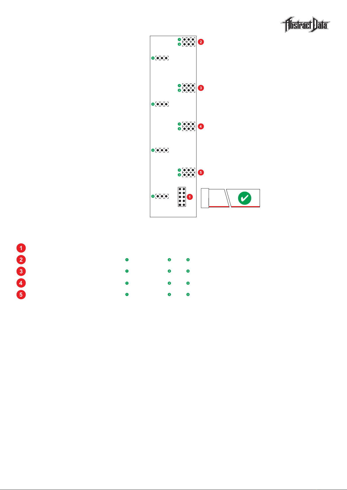
Power Requirements: +/-12V: 10-16-pin IDC connector
Current Draw: +12V: Approx. 55mA average
-12V: Approx. 45mA average
+5V: NA
Dimensions: Width: 6HP
Depth: 28mm [Panel to IDC connector]
Supplied Accessories: Cable: 1x 10-16-pin, IDC cable
Screws: 4x M3
CREDITS: Beta Testing: Radek Rudnicki
Ben Wilson
CONTACT: Justin Owen @ Abstract Data
www.abstractdata.biz
facebook.com/abstractdatabiz
twitter.com/abstractdatabiz
instagram.com/abstractdatabiz
soundcloud.com/abstractdatabiz
youtube.com/abstractjuz
© 2017 Abstract Data Ltd. Version 1.0 October 2017
8: Specs
Page 8 of 8
Other manuals for ADE-60
1
Table of contents