AccuPel HDG-4 User manual

AccuPel
HDG-4000 Documentation – HDG-4 User Manual
HDG-4 IR Remote
Control

HDG-4000 ANALOG/DIGITAL VIDEO CALIBRATION GENERATOR HDG-4 USER MANUAL
2
AccuPel HDG-4
IR Remote Control
for the
AccuPel HDG-4000
Analog/Digital Video
Calibration Generator
USER MANUAL
Version 0.91

HDG-4000 ANALOG/DIGITAL VIDEO CALIBRATION GENERATOR HDG-4 USER MANUAL
3
Table of Contents
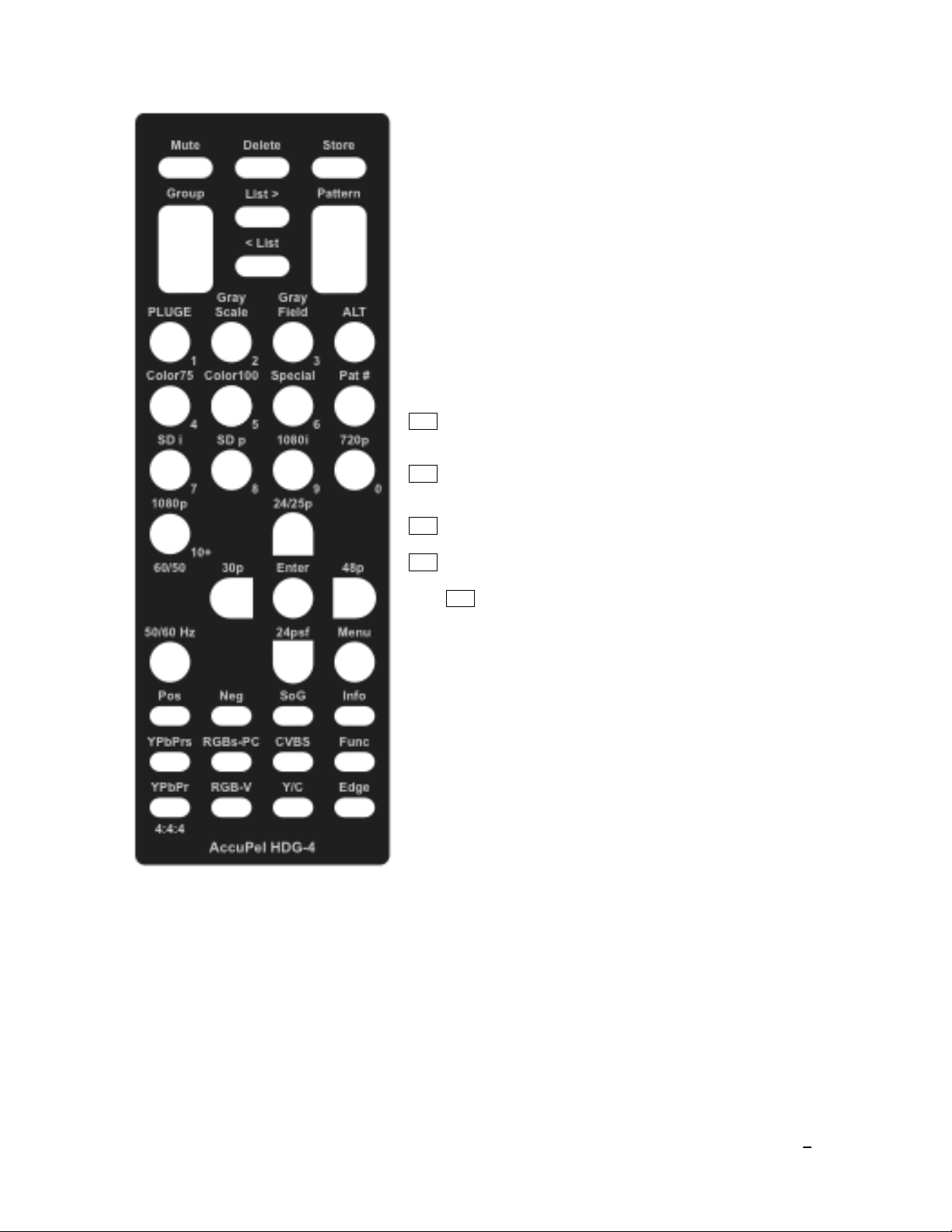
IR REMOTE CONTROL FUNCTIONS.................................................................................................... 4
OUTPUT & SYNC SELECTION .................................................................................................................... 4
YPbPr (YCbCr 4:4:4), YPbPrs (YCbCr 4:2:2), RGB-V, RGBs-PC.................................................. 4
Y/C (S-video), CVBS (Composite Video) ........................................................................................ 4
Pos, Neg, SoG (RGB Analog Sync) ................................................................................................. 4
FORMAT SELECTION ................................................................................................................................. 5
SD i, SD p, 1080i, 720p, 1080p60/50. 24p/25p, 24psf, 30p, 48p ...................................................... 5
PATTERN SELECTION ................................................................................................................................ 6
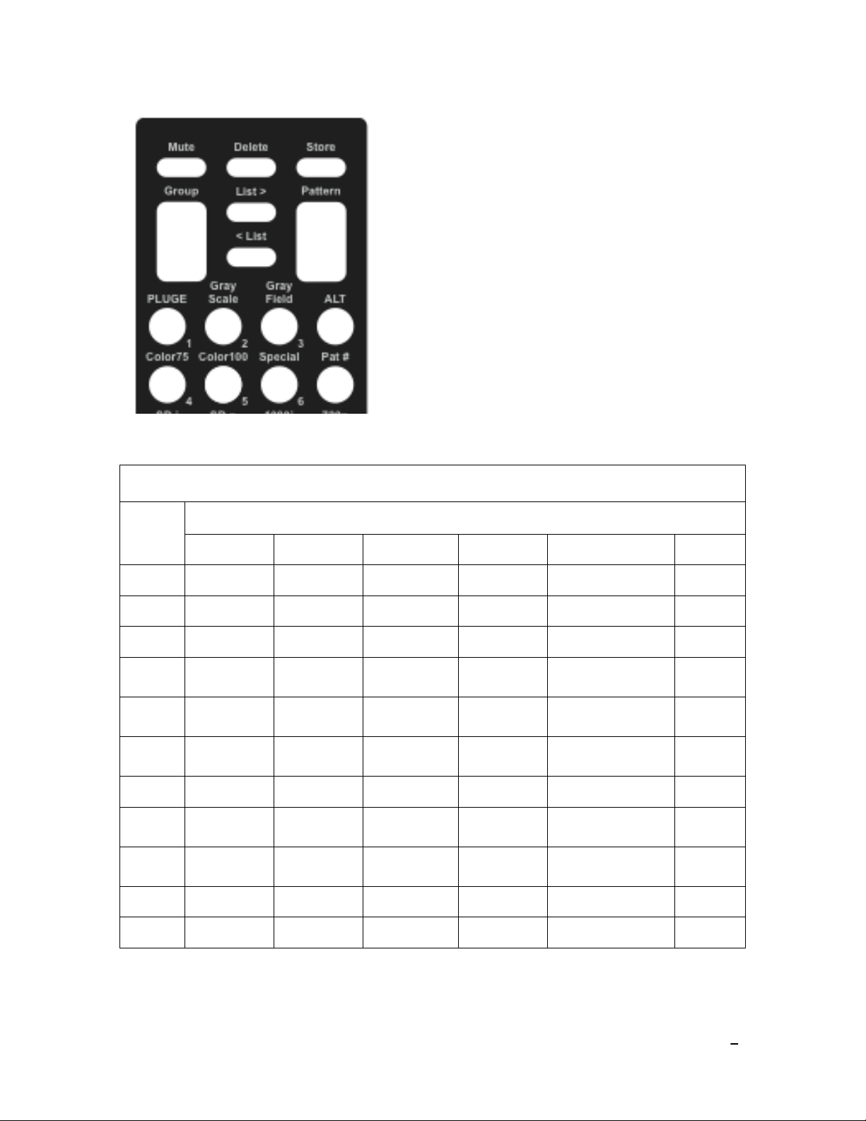
Color75, Color100, Special, PLUGE, Gray Scale, Gray Field (Groups).......................................... 6
Group ................................................................................................................................................. 6
Pattern ................................................................................................................................................ 6
Pat # ................................................................................................................................................... 6
USER-DEFINED PATTERN LIST .................................................................................................................. 7
Store (Pattern) .................................................................................................................................... 7
Delete (Pattern) .................................................................................................................................. 7
List >.................................................................................................................................................. 7
< List.................................................................................................................................................. 7
PAT # TABLE............................................................................................................................................. 7
OTHER FUNCTIONS ................................................................................................................................... 8
Edge ................................................................................................................................................... 8
Mute................................................................................................................................................... 8
Func ................................................................................................................................................... 8
ON-SCREEN-DISPLAY ............................................................................................................................... 9
Pattern Information ............................................................................................................................ 9
Info..................................................................................................................................................... 9
OSD Menu System ............................................................................................................................ 9
OSD Menu Navigation ...................................................................................................................... 9
OSD MENU............................................................................................................................................... 9
User Level........................................................................................................................................ 10
Output .............................................................................................................................................. 10
Sync ................................................................................................................................................. 10
Misc ................................................................................................................................................. 10
Com Port .......................................................................................................................................... 10
Defaults............................................................................................................................................ 10
Copyright 2007 by AccuPel, LLC
AccuPel is a trademark of AccuPel, LLC. Specifications subject to change without notice.
All Rights Reserved.
Manufactured in USA

HDG-4000 ANALOG/DIGITAL VIDEO CALIBRATION GENERATOR HDG-4 USER MANUAL
4
IR Remote Control Functions
The AccuPel HDG-4 IR (Infrared) Remote Control provides selection of all calibration patterns, signal
settings, and special modes of the AccuPel HDG-4000 Analog/Digital Video Calibration Generator. It is also
used to select settings in the HDG-4000 On-Screen Display (OSD) menu.
The HDG-4000 Format LEDs flash each time an IR remote control command is received. If an invalid
remote control command is received, the Format LEDs will blink rapidly 4-times.
Output Selection
Directly select the Output type for analog and digital video
signals.
YPbPr - Selects YPbPr analog signals (without 7.5 IRE black-
level setup), and 4:4:4 YCbCr digital signals.
YPbPrs - Selects YPbPr analog signals with 7.5 IRE black-level
setup, and 4:2:2 YCbCr digital signals.
RGB-V - selects RGB analog signals (without 7.5 IRE setup),
and RGB digital signals with standard digital video levels (digital
level 16 for black and digital level 235 for 100% reference white).
RGBs-PC - selects RGB analog signals with 7.5 IRE setup, and
RGB digital signals with PC digital video levels (digital level 0 for
black and digital level 255 for 100% reference white).
Y/C - Selects Y/C (S-video) analog signals from the 4-pin mini-
DIN connector.
CVBS - Selects CVBS (composite video) analog signals from
the 4-pin mini-DIN connector.
Note: The 7.5 IRE black-level setup on NTSC (480i) Y/C and
CVBS signals can be disabled in the OSD menu. PAL (576i) Y/C
and CVBS signals never have black-level setup.
Sync Selection
Pos, Neg, SoG –selects positive or negative analog RGB HV
sync polarity, or analog RGB signals with embedded sync-on-
green.
Note: HV sync polarity for digital signals is set according to the
EIA/CEA-861-B standard. But the digital HV sync polarity can be
overridden in the OSD menu. HD YPbPr signals and HD analog
RGB signals with SoG have Tri-level embedded sync, while SD
analog signals have Bi-level embedded sync. Bi-level embedded
sync can also be selected for HD analog signals in the OSD
menu.

HDG-4000 ANALOG/DIGITAL VIDEO CALIBRATION GENERATOR HDG-4 USER MANUAL
5
Format Selection
50/60 Hz – Selects 50 Hz or 60 Hz (59.94 Hz) generator formats.
(HDG-4000 L2 only) The selected mode is displayed on the 50
Hz, 60 Hz front panel Format LEDs.
SD i – Selects 480i (59.94 Hz) or 576i (50 Hz) signals.
SD p – Selects 480p (59.94 Hz) or 576p (50 Hz) signals.
1080i – Selects 1080i59.94, 1080i60, or 1080i50 signals.
720p – Selects 720p59.94, 720p60, or 1080i50 signals.
1080p (60/50) – Selects 1080p59.94, 1080p60, or 1080p50
signals.
ALT 24/25p – Selects 1080p23.98, 1080p24, or 1080p25
signals.
ALT 24psf – Selects 1080p23.98sf or 1080p24sf (segmented
frame) signals.
ALT 30p – Selects 1080p29.97 or 1080p30 signals.
ALT 48p – Selects 1080p47.95 or 1080p48 signals.
Note: ALT means press the ALT button first and then the
desired format button.
Note: North American standard formats are based on 59.94 Hz
(60/1.001 Hz), which is the power-up default state of the HDG-
4000. You may select 59.94 or 60 Hz HD formats in the OSD
menu. The 59.94 mode produces the 23.98p, 23.98psf, 29.97p,
and 47.95p formats (more precisely they are 24/1.001, 30/1.001,
and 48/1.001 respectively).
Note: 1080p formats are indicated on the HDG-4000 front panel
by illuminating the 1080p LED and the 60/50, 24/25, or User
LED. The 24psf, 30p, and 48p modes illuminate the User Format
LED.

HDG-4000 ANALOG/DIGITAL VIDEO CALIBRATION GENERATOR HDG-4 USER MANUAL
6
Pattern Selection
There are three methods of selecting patterns – sequential group and pattern selection, direct selection by
group and pattern # (number), and user-defined pattern lists.
Sequential Group & Pattern Selection
Group
Press the top of the Group rocker button to move forward to the
next pattern Group. Press the bottom of the Group rocker button
to move backward to the previous pattern group.
Pattern
Press the top of the Pattern rocker button to move to the next
pattern in the current pattern group. Press the bottom of the
Pattern rocker button to move to the previous pattern in the
current pattern group.
Direct Group & Pattern Selection
Color75, Color100, Special, PLUGE, Gray Scale, Gray Field -
Directly select one of the 6 major pattern groups.
ALT Gray Scale – Press this button combination to select or
alternate between 0%-10% Low-GS (Gray Scale) patterns and
100%-109% High-GS patterns. Press the Gray Scale button only
to return to the default 0%-100% Gray Scale patterns. The Gray
Scale LED will blink slowly when the Low-GS or High-GS mode
is enabled.
Note: The background of the High-GS windows is 100% luma to
examine a display’s ability to differentiate levels near 100%.
Note: 100%-109% patterns are not available for digital RGB-PC
signals because the maximum signal amplitude is 100% (digital
255) for RGB PC signals.
Pat #
Press the Pat # button followed by a number button (0-10) to
directly select a pattern in the current pattern group. The active
Group LED will flash while waiting for the number button to be
pressed. Press any other button to cancel the Pat # entry
process.
This function is primarily useful to quickly select a specific
grayscale window value in the Gray Scale group. Pattern #1
selects the 10 IRE window, pattern #2 selects the 20 IRE
window, … pattern #10 selects the 100 IRE window. When the
1%-10% Grayscale pattern group is enabled, pattern #1 selects
the 1 IRE window, pattern #2 selects the 2 IRE window, etc. The
Pat # table on the next page shows the pattern #’s for all groups.

HDG-4000 ANALOG/DIGITAL VIDEO CALIBRATION GENERATOR HDG-4 USER MANUAL
7
User-Defined Pattern List
Up to 6 patterns can be stored in the user-defined pattern list.
The user-defined pattern list is stored in the HDG-4000 and is
discarded if the power is disconnected.
Store - The currently displayed pattern is stored in the user-
defined pattern list.
Delete - The currently displayed pattern is deleted from the
user-defined pattern list.
List > - The next pattern in the user-defined pattern list
becomes the current pattern.
< List - The previous pattern in the user-defined pattern list
becomes the current pattern.
Pat # Table
Group
Pat #
Color75
Color100
Special
PLUGE
Gray Scale
Gray Field
0
75% Split
Color Bars
100% Split
Color Bars
Crosshatch
0% APL
PLUGE
User 100 (10) (90) %
Window w/PLUGE
Overscan
1
75% Color
Bars
100% Color
Bars
Inverse
Crosshatch
25% APL
PLUGE
10 (1) (100.9) %
Window w/PLUGE
Inverse
Overscan
2
75% Red
Window
100% Red
Field
Dual Needle
Pulse
50% APL
PLUGE
20 (2) (101.8) %
Window w/PLUGE
User 100%
Gray Field
3
75% Green
Window
100% Green
Field
Color
Multi-burst /
Chroma BW
25%
Window
w/PLUGE
30 (3) (102.7) %
Window w/PLUGE
0%
Gray Field
4
75% Blue
Window
100% Blue
Field
Multi-burst
50%
Window
w/PLUGE
40 (4) (103.6) %
Window w/PLUGE
25%
Gray Field
5
75% Yellow
Window
100% Yellow
Field
Cross Hair
75%
Window
w/PLUGE
50 (5) (104.5) %
Window w/PLUGE
50%
Gray Field
6
75% Cyan
Window
100% Cyan
Field
Sharpness
100% Window
w/PLUGE
60 (6) (105.4) %
Window w/PLUGE
75%
Gray Field
7
75% Magenta
Window
100%
Magenta Field
100% / 0%
Checkerboard
100%Window
w/
98% PLUGE
70 (7) (106.3) %
Window w/PLUGE
100%
Gray Field
8
User 75%
Gray Window
User 100%
Gray Field
100% / 0% Inv
Checkerboard
50/100 %
Window
w/PLUGE
80 (8) (107.2) %
Window w/PLUGE
9
User 50% / 0%
Checkerboard
90 (9) (108.1) %
Window w/PLUGE
10
U 50% / 0% Inv
Checkerboard
100 (10) (109) %
Window w/PLUGE

HDG-4000 ANALOG/DIGITAL VIDEO CALIBRATION GENERATOR HDG-4 USER MANUAL
8
Other Functions
Edge - Selects Fast or Slow analog video edge transitions. The Slow Edge mode changes the edge
transition rate of the HDG-4000 analog signals to a rate chosen specifically for each video format. The Edge
mode only affects analog signals. It does not affect the digital video output. The currently selected Output
LED will blink slowly when the Slow Edge mode is enabled.
Mute - This button produces a 0% black field. Press any button on the remote control (including Mute) to
restore the previous pattern.
Func - This button is reserved for new features.

HDG-4000 ANALOG/DIGITAL VIDEO CALIBRATION GENERATOR HDG-4 USER MANUAL
9
On Screen Display (OSD) Systems
Pattern Information
Info – Each time a pattern is changed the name of the pattern, which includes important signal
identification information, is displayed on-screen for approximately one second. Press the Info button to
display the pattern information continuously. Press the Info button again to resume the default display
period.
OSD Menu System
The OSD Menu is produced by all analog and digital outputs, for all signal formats. The OSD Menu
provides additional features such as user definable grayscale values and colors, access to advanced
signal parameters, communications port control, and the ability to specify generator power-up default
modes.
OSD Menu Navigation
Press the Menu button to display the OSD window, which is organized into three columns. The left
column of the OSD window currently lists six menus – User Level, Output, Sync, Misc, Com Ports, and
Defaults. Use the cursor keys to highlight the desired menu, and then move into the middle column and
highlight a menu item. The current status of each highlighted item is shown in the right column. To
change a setting move into the right column and highlight one of the alternative settings that will be
listed in that column. In most cases it is not necessary to press the Enter key unless “Enter” appears in
the right column. In that case highlight “Enter” and press the remote control Enter key to proceed.
Press Menu to turn the OSD menu on or off. The cursor position in the OSD menu is maintained when
the menu is turned on or off, so it is easy to turn the menu off when making measurements or adjusting
a calibration setting, and then turn it back on again to change the same menu item.

HDG-4000 ANALOG/DIGITAL VIDEO CALIBRATION GENERATOR HDG-4 USER MANUAL
10
OSD Menus
User Level
Field – Use the numeric [0-9] buttons followed by the Enter button to enter a luma integer value from 0-
109% for the User Field in the Gray Field group. To restore the original 100% User Field select Factory
and press Enter. Select “Cancel” and press Enter to leave the menu without making any change.
Window – Use the numeric [0-9] buttons followed by the Enter button to enter a luma integer value from
0-109% for the User Window in the Gray Scale group. To restore the original 100% User Window select
Factory and press Enter. Select “Cancel” and press Enter to leave the menu without making any
change.
Checkerboard – Use the numeric [0-9] buttons followed by the Enter button to enter a luma integer
value from 0-109% for the User Checkerboard and User Inverse Checkerboard in the Special group. To
restore the original 50% Checkerboard luma value select Factory and press Enter. Select “Cancel” and
press Enter to leave the menu without making any change.
Color – Use the Up and Down cursor buttons to select the R, G, or B entry field. Use the numeric [0-9]
buttons to enter R, G, or B integer values from 0-109%. Press the Enter button to enter the R, G, B
values as the new color of the User Window and User Field in the Color 75 and Color 100 groups
respectively. The “White” bars in the color bar patterns are also changed to allow comparison with other
known colors. To restore the original 75% gray and 100% white colors select Factory and press Enter.
Select “Cancel” to leave the menu without making any change.
Note: After you Enter the value changing process you can only exit that process by completing a value
entry, by highlighting Factory and pressing Enter to reset the value(s), or by highlighting Cancel and
pressing Enter. After you Cancel or Enter a new value, a “Change” option is highlighted in the menu.
Press Enter to repeat the User value entry process, or press the left cursor button to move to another
menu item.
Note: As you enter digits the digits shift to the left. Press zeros to clear a mis-typed number without
using Cancel to exit the menu.
Output
CVBS/YC – Select 0 IRE or 7.5 IRE black level setup for NTSC (480i) CVBS or Y/C signals.
Channels – Enable/disable any combination of RGB or YCbCr (YPbPr) output signals.
CVBS C BW – Select the CVBS (composite video) chroma signal bandwidth.
YC C BW – Select the Y/C (S-video) chroma signal bandwidth.
Color Matrix – Select standard YCbCr/YPbPr HD/SD Rec. 709/Rec. 601 color-matrix encoding, or
reverse the encoding (HD/SD Rec. 601/Rec. 709).
HD V Rate – Select 59.94 or 60.00 Hz HD signals.

HDG-4000 ANALOG/DIGITAL VIDEO CALIBRATION GENERATOR HDG-4 USER MANUAL
11
Sync
HD DVI – Select positive or negative HD digital sync.
HD DVI – Select positive or negative SD digital sync.
HD Y Type – Select Tri-level or Bi-level HD analog YPbPr embedded sync.
HD G Type – Select Tri-level or Bi-level HD analog RGB embedded sync (SoG).
HD HV Time – Select Normal or SMPTE analog RGB HV Sync positioning.
Y/G Phase – Select sub-pixel analog YPbPr embedded sync positioning.
Scope Trigger – Select normal analog HV sync or special V sync for an oscilloscope trigger.
Misc
Info – Serial number, levels, and options information.
Com Ports
RS232 Baud – Baud rate selection.
USB Baud – Baud rate selection.
RS232 Flow – Flow control selection.
Defaults (Power up)
60/50 Hz – Power up in 60 Hz or 50 Hz mode (HDG-4000 L2 only).
RGB Sync – Power up analog RGB signals with SoG, or Positive or Negative HV sync.
CVBS/YC – Power up with 0 IRE or 7.5 IRE setup for NTSC (480i) CVBS and Y/C signals.
RS232 Baud – Power up baud rate.
USB Baud – Power up baud rate.
User Format – Power up with front panel User Format set to select 1080p24sf, 1080p30, or 1080p48.
Save Items – Save all of the above power up defaults.
Table of contents
Popular Remote Control manuals by other brands

Daikin
Daikin BRC1D517 installation manual

Zebra
Zebra ZebraStat ZS-2 Operation manual

Hearth and Home Technologies
Hearth and Home Technologies IntelliFire Plus RC300-MON-VFL Installation & operating instructions

Marantz
Marantz RC3001/E1B Service manual

Logitech
Logitech Harmony Ultimate Hub user manual

Philips
Philips Prestigo SRU8015/10 quick start guide

HDL
HDL HDL-MTIRW product manual

ITALFILE
ITALFILE JANE TOP 01 quick start guide

Viessmann
Viessmann Vitotrol 200 operating instructions

LocknCharge
LocknCharge ECO SAFE CHARGE ELE1908 User instructions

Amazon
Amazon Fire TV Stick 4K quick start guide

Cardin Elettronica
Cardin Elettronica RCQ433-3G User instructions