AccuraSEE MINI User manual

P
ORTABLE
H
EAT
R
ECOVERY
V
ENTILATOR
Model MINI
User Manual
We aim to provide our customers with exceptional niche products that are superior to alternative options.
Our products are handcrafted and built with respectful cognizance of sustainability and quality.
Please, kindly contact us if there are any issues or errors in the User Manual.
AccuraSEE| 2022 – version 7
info@accuraseemechanical.com
Table of Contents
Introduction ................................................................................ 1
Product Description ................................................................... 1
Warning ..................................................................................... 2
Installation ................................................................................. 3
Maintenance .............................................................................. 5
Filter ................................................................................................. 5
Duct .................................................................................................. 5
Heat Exchanger ............................................................................... 6
Electrical Parts ................................................................................. 6
Caveat ....................................................................................... 6
Terms and Agreements ............................................................. 7
Return Policy .................................................................................... 7
Disclaimer ........................................................................................ 7

1
Introduction
he User Manual concisely presents the information that is needed to correctly
install and operate the product. Failure to strictly follow the instructions in the
User Manual nullifies the Terms and Agreements of the manufacturer.
Product Description
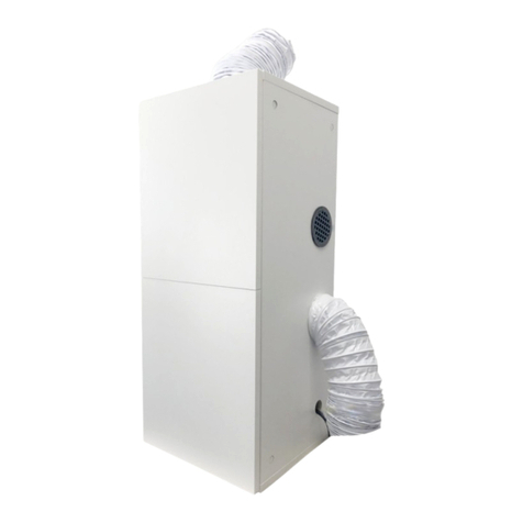
The product is a portable heat recovery ventilator which is housed in an attractive
polymer enclosure. The heat recovery ventilator performs three functions. First, it
supplies fresh air to a space (ventilation). Secondly, the fresh air that is supplied to the
space is purified with filters while pollutants such as germs, molds, excess moisture,
CO
2
, radon, odors, and particulates are expelled from the space (purification). Thirdly,
the supplied fresh air is passively heated or cooled depending on the outdoor
conditions (comfort). The product is visually depicted in Figure 1.
Exhaust vent
Supply vent
(supplies fresh & purified air)
(removes stale & polluted air)
(a) External side view.
(b) Internal top view.
Figure 1. The (a) external side and (b) internal top views of the portable heat recovery ventilator.
The approximate external dimensions of the enclosure of the product are ~15.7 in × ~11.8 in × ~6.3 in
(~39.9 cm × 29.9 cm × ~16.0 cm). The actual product that is received by the customer may slightly differ from the images in Figure 1.
Some products may carry only one or no fan controller. Note. Figure 1 is not drawn to scale.
T
I C O N K E Y
Warning
Note
†
Caveat
2
Warning
Please, observe these warnings:
Failure to comply with the warnings may result in fire, property
damage, electric shock, injury, or death.
To prevent suffocation, electric shock, injury or death, the customer
is responsible to ensure that children shall NOT access the product.
The product shall not be modified, disassembled, or serviced.
The product shall be shut down if the outdoor air temperature
exceeds 35ºC or 95ºF.
The supply and exhaust vents shall NOT be blocked.
The product comes with pre-installed supply and exhaust ducts and
their orifices shall NOT be blocked.
The enclosure shall not be opened when the product is powered.
The product operates using 12V DC and shall NOT be directly
connected to the wall power or mains electricity. It is strongly
recommended to use an AC-to-DC power adapter that is rated for
12V DC power supply and can handle at least 3A.
As soon as possible, the power adapter cord shall be safely disconnected
from the wall power if liquid spills on or around the product.
The power adapter shall only be connected to an electrical receptacle that
is permanently installed in a space.
The electrical parts of the product (i.e., power switch, power connector,
fan controller(s) – if applicable, and fans) shall not be handled.
The cables in the product shall not be disconnected, changed, or modified.
To maintain the calibration of the product, the potentiometer of the fan
controller shall not be adjusted.
NOTE
The product operates in
Normal (default) and
Boost modes. The
Boost mode is only
intended for periods
where additional
ventilation is needed
and should not be used
to permanently operate
the product.

3
Installation
Please, adhere to the following instructions when installing the product:
The product shall not be installed near hazardous or toxic materials.
The product shall only be installed in either vertical or horizontal
orientations and shall not be positioned at an oblique angle.
The product shall be installed in horizontal orientation as shown in
Figure 2(a).
The product shall be installed in vertical orientation as depicted in
Figure 2(b).
The product can be sited on a table / floor or mounted on a wall.
The product shall be installed in a space where the temperature and
relative humidity of air are within the range of 22ºC – 26ºC
(71.6ºF – 78.8ºF) and 35% – 50%, respectively.
The pre-installed supply and exhaust ducts shall be insulated.
The vents and ducts shall NOT be connected to external appliances
such as dryers, fans, furnaces, etc.
The product shall not be powered until the ducts are installed.
Window/Door: A pair of boards with each having one hole or a single
board with two holes shall be fastened to a section of a window/door, and
the ducts shall be inserted into the holes.
Wall: The ducts shall be inserted into two holes that are drilled through
the wall.
To power the product, connect the plug of the power adapter to the wall
power. Next, connect the free end of the power adapter to the power
connector port and the product will operate in the Normal mode. The
Boost mode can be activated by pressing the power switch until it latches.
To shut down the product, ensure that the Normal mode is active. Next,
disconnect the power adapter cord from the power connector port, and
disconnect the plug of the power adapter from the wall power.
NOTE
The product shall not be
installed at a location
where there is probable
contact with liquids.
NOTE
The product shall be
carefully positioned
such that it may not trip
and cause property
damage or bodily injury.
NOTE
The product shall not be
installed at a location
where there is excessive
heat or exposure to
direct sunlight.
NOTE
Accessories such as
screens, boards, duct
insulation, AC-to-DC
power adapters, self-
tapping screws, and
wall-mounting brackets
are third-party goods
which may not be
provided by the
manufacturer.
NOTE
The product may be
mounted on a wall by
using four wall-
mounting brackets and
four M5 × 10mm self-
tapping screws.
NOTE
The board(s)/wall holes
shall be ≥3 in (~7.6 cm).
NOTE
The Boost mode can be
transitioned to Normal
by simply unlatching the
power switch.
4
(a)
Horizontal orientation.
(b)
Vertical orientation.
Figure 2. Schematic depiction of the installation of the product in (a) horizontal (side view) and
(b) vertical (front view) orientations.
Although the supply duct is not visible in Figure 2(a), it may be connected to the board(s) to interface with the outdoors.
Note. Figure 2 is not drawn to scale.
RECOMMENDATIONS
Screens, which are not provided by the manufacturer, may be attached to the holes of the
board(s), ducts, or wall to prevent encroaching organisms from damaging the product or
constituting hazard to the space where the product is installed.
When installing the product, a minimum separation distance of 1 ft is recommended
between the supply and exhaust ducts.
The ducts should be installed without any bends that may impede the flow of air.
NOTE
Please comply with all
applicable codes and
regulations when
installing the product.

5
Maintenance
The product is designed to operate with minimal maintenance. However, a few
activities may be performed during the course of using the product.
The product shall be shut down before ANY maintenance activity is performed.
Filter
It is recommended to change the filters in the supply and exhaust vents at least once in
three months depending on the outdoor air quality. The procedure for changing the
filters is presented accordingly:
Gently unlock the latches of the enclosure of the product and open its lid.
To remove the supply vent, hold the enclosure of the product firmly with
one hand and carefully pull out the supply vent with the other hand.
The filter(s) are accessible in the exhaust vent and the vent itself does not
need to be removed. If applicable, a filter guard (not shown in Figure 1)
may first need to be removed from the exhaust vent before accessing the
filter(s).
MERV4:
o Supply vent: Replace the old filter in the port of the vent with one
sheet of a new MERV4 filter that is cut to a circular shape with a
diameter of 3 in (~7.6 cm).
o Exhaust vent: Repeat the above-mentioned procedure but replace
the old filter(s) using three new MERV4 filter pads.
PM2.5: Remove the old filter in the supply vent and replace it with a new
piece of folded PM2.5 filter.
Carefully re-attach the supply vent to the product.
Carefully close the lid of the enclosure and lock the latches.
Duct
A damaged duct can be replaced by using a similar duct with a diameter of 3 in
(~7.6 cm). The following steps can be followed when changing a duct:
Loosen the nuts of the clamp of the damaged duct.
Remove the damaged duct and attach a new duct.
Tighten the nuts of the clamp.
NOTE
The length of a newly
installed duct shall not
exceed 5 ft (~12.7 cm).
NOTE
Do not apply excessive
force when tightening
the clamp.
6
Heat Exchanger
The heat exchanger may be cleaned annually by implementing these steps:
Detach the supply and exhaust ducts from the board(s) or wall.
Remove the supply vent as explained in an aforementioned step.
Insert the hose of a powered vacuum cleaner into the port of the supply
vent to extract particles from the heat exchanger tubings.
Remove the hose of the vacuum cleaner from the port of the supply vent.
Re-attach the supply vent to the product.
Carefully insert the vacuum cleaner hose by up to 2 ft (~60.9 cm) into the
exhaust duct to extract particles from the shell side of the heat exchanger.
Ensure that the exhaust duct is not damaged while inserting the hose.
Remove the hose of the vacuum cleaner from the exhaust duct.
Re-attach the supply and exhaust ducts to the board(s) or wall.
Electrical Parts
An electrical part shall only be replaced if it is faulty. In this situation, the product shall
be shut down and a qualified service technician may be consulted.
Caveat
The electrical parts of the product are deemed to be certified to ensure customer safety.
Notably, the product operates on the load side of a Class 2 power source in accordance
with Canada Electric Code Rule 16–222 and US National Electric Code Class 2
Article 725–41. The product is also subject to the exemption(s) outlined in Federal
Communications Commission Section 15.103(d). Consequently, the manufacturer is
not liable if additional approval is required by the Authority Having Jurisdiction where
the product is purchased and/or installed.
NOTE
The heat exchanger shall
not be washed.
†

7
Terms and Agreements
The product is protected by intellectual property and shall not be reverse-engineered,
imitated, and copied except under an approved licensing agreement with the
manufacturer.
Return Policy
Please, check the return policies of the online merchant(s) and store
owner(s) from whom the product was purchased.
Disclaimer
The warranty does not apply to defects that are caused by normal wear and
tear, normal corrosion, and normal failure that ensue from the operation
of electrical or mechanical devices.
The warranty does not extend to products that have been subject to
misuse, neglect, abuse, alteration, testing, improper installation, improper
storage, improper maintenance, improper handling during shipping,
unauthorized attempts to repair, accident, fire, lightning or other hazard,
and damage by current, temperature, physical stress, and deviation from
the environmental specifications of a conditioned space that is stated in the
User Manual.
The warranty does not extend to products that have been modified,
disassembled, serviced, or reassembled by a third party.
The warranty is exclusive and in lieu of all other warranties, expressed or
implied, including, without limitation, any warranty of merchantability or
fitness for a specific purpose. Without limiting the generality of the
foregoing, the manufacturer disclaims any other claim against the
manufacturer (whether arising by operation of law or otherwise), including
any claim or liability for special, indirect or consequential damages of any
kind relating to or arising out of the product or any part thereof.
The manufacturer’s obligation is limited to repair or replacement, at the
option of the manufacturer, of any product determined to be defective in
workmanship or material during the applicable warranty period, subject to
the fact that the warranty:
o Covers the heat exchanger for a maximum period of five years
from the date of purchase by the customer;
o Covers the electrical parts for a maximum period of one year from
the date of purchase by the customer;
o Does not cover the enclosure;
NOTE
The manufacturer
provides a warranty for
the product that is
subject to a Disclaimer.
8
o Does not cover goods and services that are sourced from third-
party suppliers and sold or delivered to the customer “as is”.
The manufacturer neither assumes nor authorizes any person to assume
for it any other liability in connection with the manufacture, sale, shipping,
delivery, installation, and operation of the product or any part thereof
except as aforesaid.
Table of contents
Other AccuraSEE Fan manuals
Popular Fan manuals by other brands

Comfort Zone
Comfort Zone CZHV12B Series manual

Pro Breeze
Pro Breeze PB-F15B instruction manual

Ebmpapst
Ebmpapst S3G450-AO02-32 operating instructions

OEM Tools
OEM Tools 24878 Operating instructions and parts manual

Ebmpapst
Ebmpapst A2D250-AA02-47 operating instructions

Air King
Air King AK905 installation instructions

Ebmpapst
Ebmpapst A3G630-AC52-58 operating instructions

Ebmpapst
Ebmpapst G1G170-AB31-53 operating instructions

Ebmpapst
Ebmpapst G1G160-BH39-52 operating instructions

HAMPTON BAY
HAMPTON BAY SW18030 ORB Use and care guide

HAMPTON BAY
HAMPTON BAY MYRON 36LGM-L Use and care guide

Ebmpapst
Ebmpapst 4414/2MP operating manual