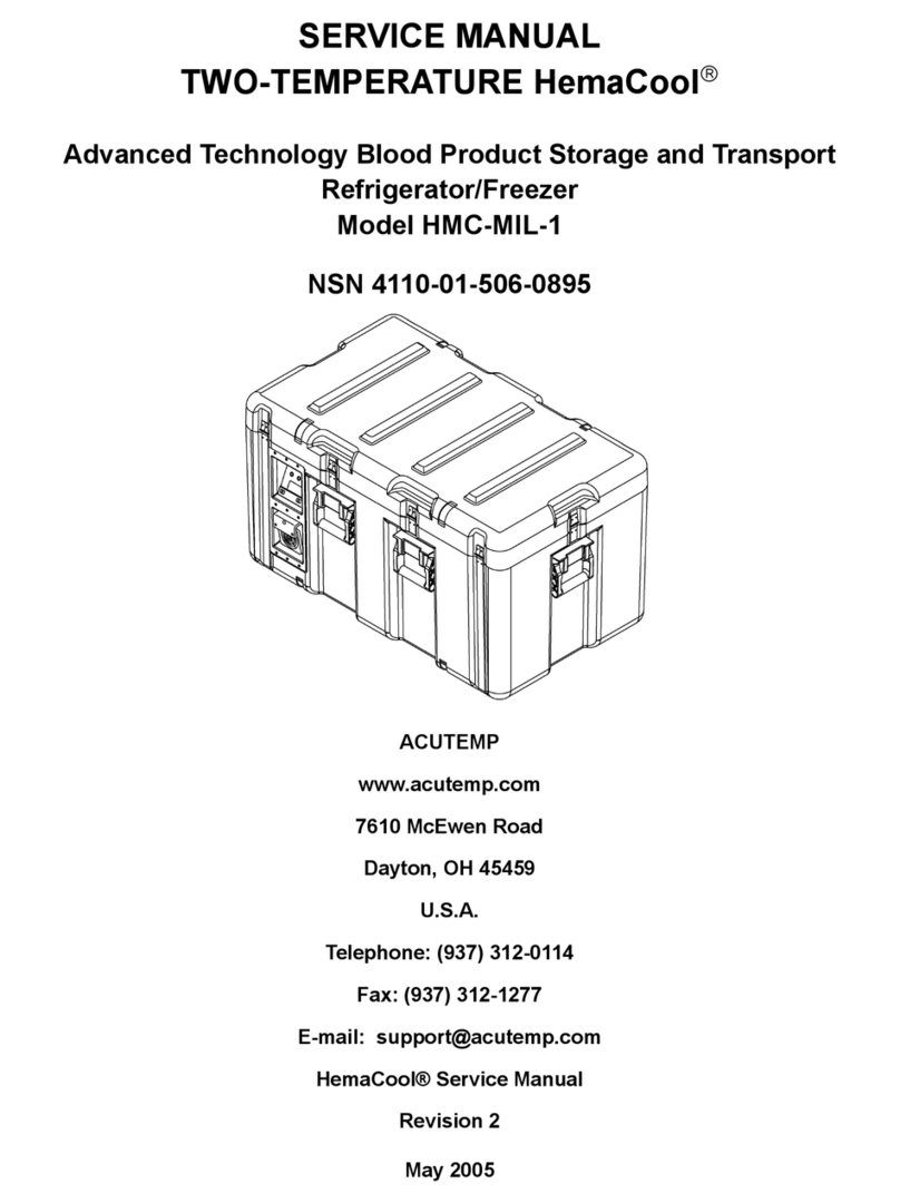
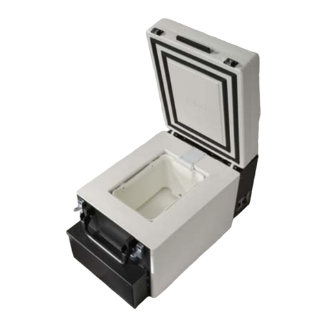
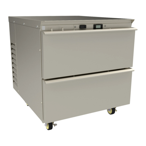
AcuTemp HemaCool HMC-MIL-1 User manual

May 2005
OPERATING INSTRUCTION
TWO-TEMPERATURE HemaCool®
Advanced Technology Blood Product Storage and Transport
Refrigerator/Freezer
Model HMC-MIL-1
NSN 4110-01-506-0895
ACUTEMP
www.acutemp.com
7610 McEwen Road
Dayton, OH 45459
U.S.A.
Telephone: (937) 312-0114
Fax: (937) 312-1277
E-mail: [email protected]
HemaCool® Operating Instruction
Revision 2


HemaCool®Operating Instruction
TOC-i/TOC-ii blank REV 2
Table of Contents
Page
Chapter 1. Introduction . . . . . . . . . . . . . . . . . . . . . . . . . . . . . . . . . . . . . . . . . . . . . . . . . . . . . . . . . . . . . 1-1
Section I. System Familiarization . . . . . . . . . . . . . . . . . . . . . . . . . . . . . . . . . . . . . . . . . . . . . . . . 1-1
1-1. Equipment Description . . . . . . . . . . . . . . . . . . . . . . . . . . . . . . . . . . . . . . . . . . . . . . 1-1
1-2. Features . . . . . . . . . . . . . . . . . . . . . . . . . . . . . . . . . . . . . . . . . . . . . . . . . . . . . . . . . 1-2
1-3. Physical Specifications . . . . . . . . . . . . . . . . . . . . . . . . . . . . . . . . . . . . . . . . . . . . . . 1-4
1-4. Operational Specifications . . . . . . . . . . . . . . . . . . . . . . . . . . . . . . . . . . . . . . . . . . . 1-4
1-5. Normal Operation . . . . . . . . . . . . . . . . . . . . . . . . . . . . . . . . . . . . . . . . . . . . . . . . . . 1-5
Section II. Operator Controls and Displays . . . . . . . . . . . . . . . . . . . . . . . . . . . . . . . . . . . . . . . . . 1-7
1-6. Power Panel . . . . . . . . . . . . . . . . . . . . . . . . . . . . . . . . . . . . . . . . . . . . . . . . . . . . . . 1-7
1-7. Display and Control Panel . . . . . . . . . . . . . . . . . . . . . . . . . . . . . . . . . . . . . . . . . . . 1-8
1-8. Displays and Alerts . . . . . . . . . . . . . . . . . . . . . . . . . . . . . . . . . . . . . . . . . . . . . . . . . 1-10
1-9. Audible Alarm . . . . . . . . . . . . . . . . . . . . . . . . . . . . . . . . . . . . . . . . . . . . . . . . . . . . . 1-11
1-10. Keys . . . . . . . . . . . . . . . . . . . . . . . . . . . . . . . . . . . . . . . . . . . . . . . . . . . . . . . . . . . . 1-11
1-11. LCD Display . . . . . . . . . . . . . . . . . . . . . . . . . . . . . . . . . . . . . . . . . . . . . . . . . . . . . . 1-12
1-12. Battery Status and Charging. . . . . . . . . . . . . . . . . . . . . . . . . . . . . . . . . . . . . . . . . . 1-16
1-13. Charge Status . . . . . . . . . . . . . . . . . . . . . . . . . . . . . . . . . . . . . . . . . . . . . . . . . . . . . 1-17
1-14. Control Modes. . . . . . . . . . . . . . . . . . . . . . . . . . . . . . . . . . . . . . . . . . . . . . . . . . . . . 1-17
1-15. Power States. . . . . . . . . . . . . . . . . . . . . . . . . . . . . . . . . . . . . . . . . . . . . . . . . . . . . . 1-18
1-16. Logging . . . . . . . . . . . . . . . . . . . . . . . . . . . . . . . . . . . . . . . . . . . . . . . . . . . . . . . . . . 1-19
1-17. Serial/IR Ports. . . . . . . . . . . . . . . . . . . . . . . . . . . . . . . . . . . . . . . . . . . . . . . . . . . . . 1-20
1-18. HemaLog Program . . . . . . . . . . . . . . . . . . . . . . . . . . . . . . . . . . . . . . . . . . . . . . . . . 1-21
Chapter 2. Operation . . . . . . . . . . . . . . . . . . . . . . . . . . . . . . . . . . . . . . . . . . . . . . . . . . . . . . . . . . . . . . . 2-1
2-1. Safety and Precautions. . . . . . . . . . . . . . . . . . . . . . . . . . . . . . . . . . . . . . . . . . . . . . 2-1
2-2. Equipment Care . . . . . . . . . . . . . . . . . . . . . . . . . . . . . . . . . . . . . . . . . . . . . . . . . . . 2-2
2-3. Handling . . . . . . . . . . . . . . . . . . . . . . . . . . . . . . . . . . . . . . . . . . . . . . . . . . . . . . . . . 2-2
2-4. Startup Procedures . . . . . . . . . . . . . . . . . . . . . . . . . . . . . . . . . . . . . . . . . . . . . . . . . 2-4
2-5. Change of Mode . . . . . . . . . . . . . . . . . . . . . . . . . . . . . . . . . . . . . . . . . . . . . . . . . . . 2-9
2-6. Loading . . . . . . . . . . . . . . . . . . . . . . . . . . . . . . . . . . . . . . . . . . . . . . . . . . . . . . . . . . 2-9
Chapter 3. Operator Maintenance and Troubleshooting . . . . . . . . . . . . . . . . . . . . . . . . . . . . . . . . . . . . 3-1
Section I. Operator Troubleshooting . . . . . . . . . . . . . . . . . . . . . . . . . . . . . . . . . . . . . . . . . . . . . . 3-1
3-1. Troubleshooting . . . . . . . . . . . . . . . . . . . . . . . . . . . . . . . . . . . . . . . . . . . . . . . . . . . 3-1
Section II. Operator Maintenance Task Details . . . . . . . . . . . . . . . . . . . . . . . . . . . . . . . . . . . . . . 3-2
3-2. Change Fuses. . . . . . . . . . . . . . . . . . . . . . . . . . . . . . . . . . . . . . . . . . . . . . . . . . . . . 3-2
3-3. Clean Intake Filters . . . . . . . . . . . . . . . . . . . . . . . . . . . . . . . . . . . . . . . . . . . . . . . . . 3-3
3-4. Inspect Lid Gaskets . . . . . . . . . . . . . . . . . . . . . . . . . . . . . . . . . . . . . . . . . . . . . . . . 3-6
3-5. Inspect for Moisture Accumulation . . . . . . . . . . . . . . . . . . . . . . . . . . . . . . . . . . . . . 3-8
3-6. Inspect for Battery Terminal Corrosion . . . . . . . . . . . . . . . . . . . . . . . . . . . . . . . . . . 3-8
3-7. Keep Batteries Charged . . . . . . . . . . . . . . . . . . . . . . . . . . . . . . . . . . . . . . . . . . . . . 3-10
3-8. Other Repair and Maintenance. . . . . . . . . . . . . . . . . . . . . . . . . . . . . . . . . . . . . . . . 3-10
Chapter 4. Accessories . . . . . . . . . . . . . . . . . . . . . . . . . . . . . . . . . . . . . . . . . . . . . . . . . . . . . . . . . . . . . 4-1
Chapter 5. Miscellaneous . . . . . . . . . . . . . . . . . . . . . . . . . . . . . . . . . . . . . . . . . . . . . . . . . . . . . . . . . . . 5-1
Section I. HemaCool® Specifications . . . . . . . . . . . . . . . . . . . . . . . . . . . . . . . . . . . . . . . . . . . . . 5-1
5-1. Model HMC-1-MIL. . . . . . . . . . . . . . . . . . . . . . . . . . . . . . . . . . . . . . . . . . . . . . . . . . 5-1
Section II. WARRANTY . . . . . . . . . . . . . . . . . . . . . . . . . . . . . . . . . . . . . . . . . . . . . . . . . . . . . . . . 5-2
Appendix A. Schematics and Board Layouts . . . . . . . . . . . . . . . . . . . . . . . . . . . . . . . . . . . . . . . . . . . . . . A-1
Control Motherboard Layout . . . . . . . . . . . . . . . . . . . . . . . . . . . . . . . . . . . . . . . . . . A-1
Control Motherboard Schematic (Sheet 1 of 2) . . . . . . . . . . . . . . . . . . . . . . . . . . . A-2
Control Motherboard Schematic (Sheet 2 of 2) . . . . . . . . . . . . . . . . . . . . . . . . . . . A-3
Display Circuit Board Layout. . . . . . . . . . . . . . . . . . . . . . . . . . . . . . . . . . . . . . . . . . A-4
Display Circuit Board Schematic. . . . . . . . . . . . . . . . . . . . . . . . . . . . . . . . . . . . . . . A-5


HemaCool®Operating Instruction
1-1 REV 2
CHAPTER 1. INTRODUCTION
Section I. System Familiarization
a. The HemaCool®is a conventional liquid/vapor-phase refrigerator with a number of special enhancements:
(1) HemaCool®employs vacuum insulation panels to decrease the power required to regulate temperature in a given
environment, to increase holdover time when energy sources are lost or disconnected, and to increase internal
temperature stability.
(2) In the COOL mode (4°C (39ºF) set point), the unit prevents payload freezing in sub-zero environments by
applying heat, rather than cooling.
(3) The unit's control system works with a number of different power sources without special adapters. This power
system includes internal batteries that allow the HemaCool®to operate for a time without external power (see
Operational Specifications, Paragraph 1-4).
(4) The HemaCool®includes integral monitoring and logging of payload compartment temperature and battery
charging state.
(5) The HemaCool's®internal design is arranged to accept baskets for holding blood bags (or fresh frozen plasma
bags when the unit is operating in freezer mode).
(6) Small internal fans help circulate cooling air, to maintain uniform temperature.
b. The HemaCool®is designed to preserve liquid or frozen blood products and medical supplies. HemaCool®provides
exceptional field storage through its combination of superior insulation technology and temperature controls, based
on microcontroller solid-state electronics.
c. The HemaCool®is portable and self-powered, utilizing internal batteries. The system will accept electrical power
from multiple sources, e.g., 12-28 VDC from batteries or other DC sources at the DC power input, or from a wide
range of grid power standards (any combination of 100-250 VAC and 50-60 Hz line frequencies) at the AC power
input.
d. If the unit is fully stocked with conditioned contents and no power is applied (unit off), it will take more than 2 hours
for the internal payload temperature to rise from 4°C (39°F) to 6°C (43°F) in an ambient temperature of 49°C
(120°F).
(1) The HemaCool®will perform in either the COOL or FREEZE mode.
(a) In the COOL mode (4°C (39°F)), the unit, provided its two internal 21-amp-hour batteries are properly
charged, will maintain a temperature range of 1°C (34°F) to 6°C (43°F) for more than 24 hours at 24°C
(75°F) ambient temperature.
1-1. EQUIPMENT DESCRIPTION

HemaCool®Operating Instruction
1-2
REV 2
(b) In FREEZE mode (-22°C (-7°F)), the unit, provided its two internal 21 amp-hour batteries are properly
charged, will keep blood products frozen for more than 8 hours, at an ambient temperature of 24°C (75°F).
Freeze mode operation does, however, reduce the battery-powered hold time. (See Operational
Specifications, Paragraph 1-4).
(2) For additional payload security, the HemaCool®is also equipped with an internal heater that will prevent a
refrigerated payload from freezing if the unit is in an environment that is below 1°C (34°F), but no lower than
-20°C (-4°F).
e. The standard default temperature scale setting for the HemaCool®is Celsius (°C).
NOTE
This manual assumes that when viewing the HemaCool®, the front is the side with the
internal lid latches. The display screen is on the left when viewed from the front. Viewed
from the front, the compressor and electronics compartment is on the left side of the
machine, while the batteries are under the cover panel on the right side.
The HemaCool®is ergonomically designed for quick response operation in the world’s harshest operating environments and
incorporates the following features. Figure 1-1 illustrates these features.
a. Tough Mil-Spec Case (1).
b. Six tie-down-rated carry handles for two- or four-person carry transportation (2).
c. Ten positive locking latches for secure storage and transport (3).
d. Power panel for control and connection to external power sources (4).
e. Display and control panel for operator interface (5).
f. Easy load/unload baskets that allow convection around packs for even cooling (6).
g. Vacuum panel insulated lid (7).
h. A cover panel to store all required cables and accessories (8).
i. The HemaCool®can be stored in temperatures from -30ºC (-22ºF) to 65ºC (149ºF).
1-2. FEATURES

HemaCool®Operating Instruction
1-3 REV 2
Figure 1-1. HemaCool®Features

HemaCool®Operating Instruction
1-4
REV 2
a. Payload volume:
2 cubic feet (56.6 liters)
b. Payload bay dimensions:
13 in. (33.0 cm) H x 14 in. (35.6 cm) W x 18 in. (45.7 cm) L
c. External dimensions:
21.8 in. (55.4 cm) H x 21 in. (53.3 cm) W x 37.5 in. (95.2 cm) L
d. Empty weight:
142 lbs (64.5 kgs)
a. Internal temperature regulation:
COOL mode: 4.0°C ±1°C (39°F ±2°F)
FREEZE mode: -22°C +0/-6°C (-7°F +0/-11°F) in 30°C (86°F) ambient or lower temperature
b. Estimated power consumption during COOL mode startup:
<40 W at room temperature (55 W at 40°C (104°F)) ambient
c. Estimated power consumption for COOL mode storage only:
<20 W at 40°C (104°F) ambient
d. Payload capacity:
40 x 450 ml units or 60 x 250 ml units.
e. Batteries:
12 volt, 42 amp-hour total capacity
• Set contains two 21 amp-hour batteries
• Battery weight (total): 27 lbs (12.2 kg)
• Provide 24 hours of operation in storage only mode
f. The HemaCool®accommodates a variety of power sources:
• Batteries or external 12-28 VDC to auxiliary input
• AC power from grid or generator
• Grid power required: Any combination of 100-250 VAC and 50-60 Hz
g. The HemaCool®employs environmentally safe R 134A refrigerant.
h. The HemaCool®is designed to be operated in temperatures from -20ºC (-4ºF) to 49ºC (120ºF).
i. The HemaCool®can be stored in temperatures from -30ºC (-22ºF) to 65ºC (149ºF).
1-3. PHYSICAL SPECIFICATIONS
1-4. OPERATIONAL SPECIFICATIONS

HemaCool®Operating Instruction
1-5 REV 2
a. Figure 1-2 is a functional block diagram of the HemaCool®as described below.
b. In normal operation, the evaporator temperature sensor (Figure 1-2) is monitored by the control board processor chip,
which compares its output to an internal look-up table. This table lists the evaporator temperatures that the
compressor should turn on and off to maintain the temperature selected on the power panel. The on/off function is
performed by an optically isolated MOSFET switch on the control board that is routed to the compressor through the
power board. This switch acts in place of the conventional thermostat switch to tell the compressor driver to run the
compressor and fans.
c. The compressor can operate in two speed settings: slow or fast. Each time the compressor is started, it runs in slow
speed. If the compressor runs continuously for 2 minutes, and the temperature has still not reached the desired target,
the compressor switches to fast speed. It continues to run in fast speed until it cycles, or is turned off.
d. When the control temperature selection is changed, it tells the control board processor to use a different look-up table.
e. Because thermal contact between the evaporator and the payload is made through air circulated by the internal fans, it
is imperfect. In above 0ºC (32ºF) ambient temperatures, this means the evaporator runs cooler than the payload
temperature. The only exception is when the heater operates to prevent payload freezing in outside ambient
temperatures of below 0ºC (32ºF).
f. Because of the temperature difference between the payload and the evaporator, as well as to have faster response, the
temperature sensor for the evaporator is separate from the payload compartment temperature sensor and mounted
directly on the evaporator.
g. The payload compartment temperature sensor is monitored by the microprocessor to alert it to any failure of the
temperature regulating system and to generate the temperature readout in the display. Temperature information
supplied to the data logger is provided by the payload, evaporator, and ambient sensors.
h. The processor takes a new reading of the temperature (and also of battery voltage) every 1.25 seconds. It averages
eight readings before updating the display. This means the display updates every 10 seconds.
i. When the unit is operating on DC from its batteries or DC auxiliary power, the internal and external fans operate only
when the control board operates the compressor.
j. When AC power is available, the AC to DC converter runs constantly to keep the batteries charged, and the
condenser coil blower runs constantly to exhaust heat from the converter. The internal fans are switched through a
magnetic reed switch operated by the payload compartment lid. If the lid is open, the internal fans are turned off to
prevent the mixing of outside air with the payload.
k. The control board determines which power source is used to operate the unit. This ensures the AC supply takes over
for the batteries and charges them during operation. A manual temperature or other change may not be displayed for
10 seconds.
1-5. NORMAL OPERATION

HemaCool®Operating Instruction
1-6
REV 2
Figure 1-2. Functional Block Diagram

HemaCool®Operating Instruction
1-7 REV 2
Section II. Operator Controls and Displays
The power panel (Figure 1-3) in the compressor and electronics compartment has input connectors for auxiliary DC power and
for an AC power cord. The AC power connector is fused by two fuses on this panel. Two fuses are employed because the unit
will operate on either 115 VAC or 230 VAC. Operation on 230 VAC requires both non-ground leads to be fused.
1-6. POWER PANEL
ITEM DESCRIPTION FUNCTION
1 AC Power Source Connector Connection to AC external power sources
2 DC Power Connector Connection to DC power sources
3 Line Fuses Operator replaceable overload protection
Figure 1-3. Power Panel

HemaCool®Operating Instruction
1-8
REV 2
The display and control panel (Figure 1-4) contains the LCD and LED displays and operator controls. The panel also includes
the infrared communication port device (IrDA standard) and RS-232 serial port for the data logger.
1-7. DISPLAY AND CONTROL PANEL
ITEM DESCRIPTION FUNCTION
1 Multifunction LCD Display Displays detailed information on a number of operating
parameters, and when compressor is off, the display shows IDLE.
2 Temperature LED Indicates payload compartment temperature in or out of the
selected range
3 Battery LED Indicates a charge condition of the internal 12 VDC batteries
4 RS-232 Data port Download of data logging information
5 IR (infrared) Port Download of data logging information
6 DISPLAY Key Changes LCD display screen function, displays history graph
information, and when used in conjunction with MODE button,
changes operation between COOL and FREEZE
7 MODE Key Used in conjunction with DISPLAY button to change operation
between COOL and FREEZE, toggles the display information and
diagnostic pages, and when used in conjunction with the ON/OFF
key, sets the time and date
8 ON/OFF Key Starts and shuts down unit, and when used in conjunction with the
MODE key, sets the time and date

HemaCool®Operating Instruction
1-9 REV 2
Figure 1-4. Display and Control Panel

HemaCool®Operating Instruction
1-10
REV 2
Information on the status of the HemaCool®is presented on a display panel (Figure 1-4), which employs two light emitting
diodes (LED) and a liquid crystal display (LCD) that includes four rows of text.
a. LEDS
Two multicolored LED indicators provide temperature and battery status alarms. The temperature LED (on the left)
shows GREEN when the temperature is in the selected range and RED when it is outside that range. In the COOL
mode, it will also turn YELLOW, when the unit is switching between compressor and heater operation. This happens
if the ambient temperature drops below or rises above 0°C (32°F) of the control temperature. The battery status LED
(on the right) shows GREEN when the battery has 10 percent or more of charge, YELLOW when it has less than
10 percent of charge, and RED when the charge nears 0 percent. When the unit is operated on AC power, the battery
status (right LED) should always illuminate GREEN or change to GREEN within a few minutes as the internal
battery recharges.
b. Temperature LED indicators
The tables below show the exact temperatures and voltages that trigger the LED color changes for different set points.
(1) Temperatures for COOL mode.
(2) Temperatures for FREEZE mode.
c. Battery Voltage LED Indicators
The tables below show the exact voltages that trigger the LED color changes:
1-8. DISPLAYS AND ALERTS
LED COLOR PAYLOAD SPACE TEMPERATURE
GREEN Between 1.0°C (34°F) and 6.0°C (43°F)
RED 1.0°C (34°F) or below or 6.0°C (43°F) and above
LED COLOR PAYLOAD SPACE TEMPERATURE
GREEN Below -20°C (-4°F)
RED -20°C (-4°F) or above
LED COLOR BATTERY VOLTAGE
GREEN 11.8 V and above
YELLOW Between 11.5 V and 11.8 V
RED 11.5 V and below

HemaCool®Operating Instruction
1-11 REV 2
a. The HemaCool®has an audible alarm. The alarm sounds only when the unit is operating on AC power and is set
from COOL mode to FREEZE mode or vice versa. The alarm continues to sound until the unit reaches temperature
range. The alarm also sounds when a RED alarm condition occurs. A RED alarm condition occurs when temperature
or battery voltage is outside its nominal operating range.
b. The alarm sounds three times at 1-second intervals in a cycle that recurs every 18 seconds. The alarm indicates that
the payload is not at required temperature and needs attention.
c. Typically, this means attaching a different applicable/available power source to maintain unit operation while
simultaneously charging its internal batteries.
NOTE
The LCD backlight comes on in response to any key activity and stays on for 30 seconds
after the last key activity.
a. The ON/OFF key has two functions. It is used to turn the HemaCool®on or off and, when used in conjunction with
the MODE key, sets the date and time.
(1) To turn the HemaCool®on or off, press and hold the ON/OFF key for 2 seconds.
NOTE
The date and time can only be set when the unit is powered by AC and idle.
(2) To set the date and time, ensure the system is powered by AC and idle, then press and hold the ON/OFF and
MODE keys simultaneously, then follow displayed text instructions.
b. The DISPLAY key has three functions. It is used to change the LCD displayed screen function, displays history
graph information, and when used in conjunction with the MODE key, changes the temperature mode selection of
COOL or FREEZE.
(1) To change the displayed screen function, press the DISPLAY key once.
(2) To display the history graph function, press the DISPLAY key twice.
(3) To alternate between COOL and FREEZE temperature modes, simultaneously press the DISPLAY and MODE
keys.
c. The MODE key has three functions. When used in conjunction with the DISPLAY key, the MODE key changes the
temperature mode selection of COOL or FREEZE. It is also used to toggle the display information and diagnostic
pages. When used in conjunction with the ON/OFF key, the MODE key sets the date and time.
(1) To alternate between COOL and FREEZE temperature modes, simultaneously press the MODE and DISPLAY
keys.
(2) To toggle the display information and diagnostic pages, press and hold the MODE key for 3 seconds.
(3) To set the date and time (only works when system is idle and running on AC power), simultaneously press and
hold the ON/OFF and MODE keys. Follow displayed text instructions.
1-9. AUDIBLE ALARM
1-10. KEYS

HemaCool®Operating Instruction
1-12
REV 2
The LCD display includes four rows of text in three information pages and two diagnostic pages.
a. Information Page 1 displays current status. Figure 1-5 shows how current status information is displayed on the LCD
display.
(1) The top row shows:
(a) Payload temperature from -30.0°C (-22°F) to 50.0°C (122°F).
(b) Payload temperature status (HIGH/LOW/OK).
(2) The second row shows:
(a) Battery charge state as a percentage.
(b) External power, if AC or AUX DC input connected.
(3) Reading from left to right, the third row of text shows:
(a) The current operating mode (COOL/FREEZE/IDLE).
(b) The current activity (COMP ON/HEAT ON) (Comp = Compressor).
(4) The fourth line shows both:
(a) The current date.
(b) The current time.
b. Information Page 2 displays the maximum and minimum temperatures for the post of operation. Figure 1-6 shows
how minimum and maximum temperature information is displayed on the LCD.
(1) The top row displays the maximum temperature within viewed data.
(2) The second row displays the date and time when the maximum temperature was first detected.
(3) The third line displays the minimum temperature detected within viewed data.
(4) The fourth line displays the date and time when the minimum temperature was first detected.
1-11. LCD DISPLAY
Temp: 7.5°C HIGH
Batt: 93% EXT POWER
Mode: Cool COMP ON
02/Jul/04 10:30:42
Figure 1-5. Information Page 1, LCD Display Current Status

HemaCool®Operating Instruction
1-13 REV 2
NOTE
These values are from within the span of data viewed in the history graph on Information
page 3; the total time span can be set by the operator.
c. Information Page 3 displays a history graph of temperature over time. Figure 1-7 shows how the history graph
information is displayed on the LCD display.
(1) The top left row displays maximum temperature within the displayed history.
(2) The second left row displays the midpoint temperature within the displayed history.
(3) The third left row displays the minimum temperature within the displayed history.
(4) The fourth row displays the time scale for the history being shown.
(5) The time scale shown starts at 0-24 hours. Each time the graph reaches the right edge, it rescales to the next
scale. Additional scales are 0-48 hours, 0-7 days, 0-14 days, and 0-30 days. In each case, the graph shows the
most recent data.
(6) Once the scale reaches the 0-30 day scale, and the graph area is filled, new data continues to scroll in and the
oldest data is lost.
(7) A vertical line is drawn on each row indicating the range of temperatures included for that time period. Each
horizontal position represents a given period of time, depending on the time scale. See the table below.
Maximum: 8.2°C
02/Jul/04 10:22:12
Minimum: 1.2°C
02/Jul/04 10:30:42
Figure 1-6. Information Page 2, LCD Minimum and Maximum Temperature Display
6.0
3.5
1.0
<graph area>
0 hours 24
Figure 1-7. Information Page 3, LCD History Graph Display
Time Scale
Time Period Per Horizontal
Position (hh:mm)
0-24 hours 00:20
0-48 hours 00:40
0-7 days 02:20
0-14 days 04:40
0-30 days 10:00

HemaCool®Operating Instruction
1-14
REV 2
NOTE
If a large amount of data has been collected, the unit might require up to several minutes to
complete the rescale.
(8) To change the time span, the unit must be Idle with AC power connected. Press and hold the DISPLAY key for
3 seconds, then follow the prompts.
d. Diagnostic Page 1 displays charge control status. Figure 1-8 shows how charge control diagnostics information is
displayed on the LCD.
(1) The top row displays:
(a) The current level of battery charge as a percentage.
(b) The LMD register.
(2) The second row displays:
(a) The FLGS1 register.
(b) The FLGS2 register.
(3) The third row displays:
(a) The NACH register.
(b) The NACL register.
NOTE
Register values are shown in hex.
(4) The fourth row displays:
(a) Charge status.
(b) Input levels.
NOTE
Input levels are:
• L for Logic 0
• H for Logic 1
• * for Pulsing
Batt: 0% LMD: 6A
FLGS1: 42 FLGS2: 02
NACH: 00 NACL: 00
Pending (temp) LL*
Figure 1-8. Diagnostic Page 1, LCD Charge Control Diagnostics

HemaCool®Operating Instruction
1-15 REV 2
e. Diagnostic Page 2 displays cooling system control status. Figure 1-9 shows how cooling diagnostic information is
displayed on the LCD.
(1) The top row displays:
(a) Revision date.
(b) Serial number.
(c) Keys.
(d) Lid switch.
(2) The second row displays:
(a) Payload temperature.
(b) Evaporator temperature.
(3) The third row displays:
(a) Ambient temperature.
(b) Battery voltage.
(4) The fourth row displays:
(a) Control activity.
(b) Activity time.
1The compressor can operate in either slow or fast speed. Each time the compressor is started, it runs in
slow speed. If the compressor runs continuously for 2 minutes, and the temperature still has not reached
the desired target, the compressor switches to fast speed. It continues to run in fast speed until it is
turned off. The display will show COMP, indicating compressor is running at slow speed, or the
display will show COMP F, indicating compressor is running at fast speed. The display will also show
COMP ON time nn, where nn is the number seconds the compressor has been running on slow speed.
2When the compressor is started, it always runs for at least 30 seconds at slow speed, unless the
controller switches to low power (e.g., switched to idle while running on batteries) or the evaporator
temperature drops below freezing while in cooling mode. During the initial 30 seconds of run time, the
display will show COMP Starting nn, where nn is the number of seconds remaining in the 30-second
minimum time.
3When the compressor is stopped, it remains off for at least 60 seconds. During the initial 60 seconds of
off time, the display will show COMP Stopping nn, where nn, is the number of seconds remaining in the
60-second minimum time.
4When the heater operates to prevent payload freezing in outside ambient temperatures of below 0°C
(32°F), the display will show HEAT.
10/Aug/04 Keys 123L
P: 4.23 E: 4.23
A: 15.19 B: 15.19
COMP Starting 12
Figure 1-9. Diagnostic Page 2, LCD Cooling System Diagnostics

HemaCool®Operating Instruction
1-16
REV 2
The battery charge level, shown on Information Page 1 of the display (and on Diagnostic Page 1), indicates the remaining
battery capacity.
a. Initial Operation
(1) To achieve an accurate measure, the internal “gas gauge” records the amount of charge applied to the batteries
and the amount of power pulsed from the batteries by the HemaCool®system.
(2) After initial connection of new batteries, the charge level is unknown and is shown as 0%.
(3) After the unit has cycled through a complete discharge and charge cycle, the level is very accurate, and the
accuracy continues to improve as additional cycles are observed.
(4) Even if the level shows 0%, as long as there is charge remaining in the batteries, the system will continue to
operate.
b. Discharged Batteries
(1) When the batteries become fully discharged, the unit switches to a low power mode and will not operate until an
external AC or DC power source is connected.
(2) If AC power is applied, the display is activated with control IDLE. The ON/OFF button can then be used to start
the cooling or freezing operation.
(3) If DC power is applied, the system remains off, but responds to the ON/OFF button, allowing operation to be
started. Note that it may take 30 seconds after connection of DC power before the ON/OFF key will respond.
c. Failed or Missing Batteries
(1) If the batteries are faulty (i.e., cannot be charged) or disconnected, and AUX DC power is applied, the LCD
display will not turn on, but the battery and/or temperature LEDs will flash. The beeper may also sound.
(2) Even in this case, the unit will operate when AC power is connected.
(3) To confirm this condition, connect AC power; the LCD then turns on, and Diagnostics Page 1 indicates “Battery
absent” or “**Fault**”.
1-12. BATTERY STATUS AND CHARGING
Other manuals for HemaCool HMC-MIL-1
1
This manual suits for next models
1
Table of contents
Other AcuTemp Refrigerator manuals
