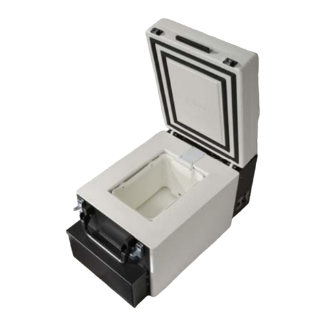
AcuTemp HemaCool HMC-MIL-1 User manual

May 2005
SERVICE MANUAL
TWO-TEMPERATURE HemaCool®
Advanced Technology Blood Product Storage and Transport
Refrigerator/Freezer
Model HMC-MIL-1
NSN 4110-01-506-0895
ACUTEMP
www.acutemp.com
7610 McEwen Road
Dayton, OH 45459
U.S.A.
Telephone: (937) 312-0114
Fax: (937) 312-1277
E-mail: [email protected]
HemaCool® Service Manual
Revision 2


HemaCool®Service Manual
i/ii blank REV 2
Table of Contents
Page
Chapter 1. General Repair Work Information . . . . . . . . . . . . . . . . . . . . . . . . . . . . . . . . . . . . . . . . . . . . 1-1
1-1. Scope . . . . . . . . . . . . . . . . . . . . . . . . . . . . . . . . . . . . . . . . . . . . . . . . . . . . . . . . . . . 1-1
1-2. Principles of Operation . . . . . . . . . . . . . . . . . . . . . . . . . . . . . . . . . . . . . . . . . . . . . . 1-2
1-3. Normal Operation . . . . . . . . . . . . . . . . . . . . . . . . . . . . . . . . . . . . . . . . . . . . . . . . . . 1-6
Chapter 2. Maintenance Procedures . . . . . . . . . . . . . . . . . . . . . . . . . . . . . . . . . . . . . . . . . . . . . . . . . . . 2-1
2-1. Part Replacement Maintenance Procedures . . . . . . . . . . . . . . . . . . . . . . . . . . . . . 2-1
2-2. Replacing Fuses . . . . . . . . . . . . . . . . . . . . . . . . . . . . . . . . . . . . . . . . . . . . . . . . . . . 2-4
2-3. Cleaning the Air Intake Filters. . . . . . . . . . . . . . . . . . . . . . . . . . . . . . . . . . . . . . . . . 2-5
2-4. Replacement of Batteries . . . . . . . . . . . . . . . . . . . . . . . . . . . . . . . . . . . . . . . . . . . . 2-9
2-5. Replacement of Fusible Link Assembly . . . . . . . . . . . . . . . . . . . . . . . . . . . . . . . . . 2-12
2-6. Replacement of Inner Lid Gasket . . . . . . . . . . . . . . . . . . . . . . . . . . . . . . . . . . . . . . 2-14
2-7. Replacement of Inner Lid Assembly . . . . . . . . . . . . . . . . . . . . . . . . . . . . . . . . . . . . 2-17
2-8. Replacement of Power Supply . . . . . . . . . . . . . . . . . . . . . . . . . . . . . . . . . . . . . . . . 2-20
2-9. Replacement of Control Motherboard. . . . . . . . . . . . . . . . . . . . . . . . . . . . . . . . . . . 2-23
2-10. Replacement of 3.6 Volt Lithium Backup Battery . . . . . . . . . . . . . . . . . . . . . . . . . . 2-26
2-11. Replacement of Condenser Fan Assembly . . . . . . . . . . . . . . . . . . . . . . . . . . . . . . 2-28
2-12. Replacement of Display Main PC Board. . . . . . . . . . . . . . . . . . . . . . . . . . . . . . . . . 2-32
2-13. Replacement of Compressor Connector Board . . . . . . . . . . . . . . . . . . . . . . . . . . . 2-35
2-14. Troubleshooting . . . . . . . . . . . . . . . . . . . . . . . . . . . . . . . . . . . . . . . . . . . . . . . . . . . 2-37
Chapter 3. Illustrated Parts List . . . . . . . . . . . . . . . . . . . . . . . . . . . . . . . . . . . . . . . . . . . . . . . . . . . . . . . 3-1
Appendix A. Schematics and Board Layouts . . . . . . . . . . . . . . . . . . . . . . . . . . . . . . . . . . . . . . . . . . . . . . A-1
Control Motherboard Layout . . . . . . . . . . . . . . . . . . . . . . . . . . . . . . . . . . . . . . . . . . A-1
Control Motherboard Schematic (Sheet 1 of 2) . . . . . . . . . . . . . . . . . . . . . . . . . . . A-2
Control Motherboard Schematic (Sheet 2 of 2) . . . . . . . . . . . . . . . . . . . . . . . . . . . A-3
Display Circuit Board Layout. . . . . . . . . . . . . . . . . . . . . . . . . . . . . . . . . . . . . . . . . . A-4
Display Circuit Board Schematic. . . . . . . . . . . . . . . . . . . . . . . . . . . . . . . . . . . . . . . A-5


HemaCool®Service Manual
1-1 REV 2
CHAPTER 1. GENERAL REPAIR WORK INFORMATION
NOTE
This manual assumes that, when viewing the HemaCool®, the front is the side with the
internal lid latches. The display screen is on the left when viewed from the front. Viewed
from the front, the compressor and electronics compartment is on the left side of the unit,
while the batteries are under the battery side tray on the right side.
a. After reading this manual you will be able to:
(1) Perform non-disassembly maintenance.
(2) Remove the air intake filters for cleaning.
(3) Examine and replace the lid gaskets.
(4) Perform required disassembly.
b. Disassembly is required to:
(1) Change the fuses.
(2) Remove the air intake filter screens for cleaning.
(3) Change the battery set.
(4) Replace the fusible link assembly.
(5) Replace the lid gaskets.
(6) Replace the lid assembly.
(7) Replace the power supply.
(8) Replace the control motherboard.
(9) Replace the lithium battery.
(10) Replace the condenser fan assembly.
(11) Replace the display main pc board.
(12) Replace the compressor connector board.
c. If it becomes necessary to call the factory for assistance, please be ready with:
(1) The unit’s serial number.
1-1. SCOPE

HemaCool®Service Manual
1-2
REV 2
(2) A list of symptoms or problems and the circumstances in which they occur.
(3) A record of everything you see on the display.
(4) Reference steps or illustrations in this manual to describe steps you’ve already taken.
d. Inside the U.S., call toll-free 1-866-312-0114 and ask for HemaCool®technical support. Outside the U.S., dial 01-
937-312-0114. Or, you may fax the information to 937-312-1277.
a. The HemaCool®is a conventional liquid/vapor phase refrigerator with a number of special enhancements:
(1) It employs vacuum insulation panels to decrease the power required to regulate temperature in a given
environment, increase holdover time when energy sources are lost or disconnected, and increase internal
temperature stability.
(2) In its cooling mode (4°C (39ºF) set point), the unit prevents payload freezing in subzero environments by
applying heat rather than cooling.
(3) The unit's control system works with a number of different power sources without special adapters. This power
system includes internal batteries that allow the HemaCool®to operate for a time without external power (see
specifications).
(4) The HemaCool®includes integral payload compartment temperature monitoring and logging.
(5) The HemaCool’s®internal design is arranged to accept baskets for holding blood bags (or fresh frozen plasma
bags when the unit is operating in freezer mode).
(6) Small internal fans help circulate cooling air to maintain uniform temperature.
b. The HemaCool®can be divided into three major components; cooling system, power and control system, and case.
c. The cooling system consists of a compressor with an integral electronic drive module, a condensing coil, a roll-
bonded evaporator coil, and connecting tubing. The evaporator has a temperature sensing thermistor and a heater
strip attached by adhesives.
d. The power and control system includes a power panel with inputs for 12-28 VDC auxiliary power, a universal input
AC power converter to create DC from grid power or generators, the internal battery set, and power and control
circuitry. DC power routing circuitry steers the DC through Schottky diodes to run the compressor or heater, fans,
and to charge the internal batteries when the source is AC or DC auxiliary. It also powers all other circuitry except
the data logger, which has its own long-life lithium battery. The control circuit board employs a microprocessor to
monitor the thermistor on the evaporator to determine when to operate the compressor or heater. It also monitors a
separate payload compartment thermistor to provide the temperature readout and to control alarms and warning
lights. It sends the on/off signals and the audio alarm to the power board for routing to the compressor or heater. The
display and warning lights are sent to the display board mounted on the display panel on the left side of the front of
the unit.
e. The case is the platform for mounting the cooling system, controls, insulation, and batteries and for assembling the
payload compartment and internal lid inside the insulation envelope. It has a separate external lid to protect the
internal refrigerator compartment and its lid from damage during transport. This lid may be left off during the
stationary operation. The internal lid and its latches secure the seal necessary for the refrigeration compartment.
1-2. PRINCIPLES OF OPERATION

HemaCool®Service Manual
1-3 REV 2
f. The assembled case is divided into three compartments (Figure 1-1):
(1) The electronics compartment, which is on the left side when you face the display.
(2) The payload compartment, which is in the middle and is covered by a separate internal lid.
(3) The battery compartment, which is on the right side when you face the display.
Figure 1-1. HemaCool®Compartments

HemaCool®Service Manual
1-4
REV 2
g. The electronics compartment holds the compressor, condenser, condenser fan, control, and power electronics and has
the circulating air intake and exhaust ports. The power panel and display panel are also mounted from within this
compartment. The air intake filters are mounted on the power panel and the display panel.
h. The payload compartment has a liner that holds the blood bag baskets or other containers. The compartment also has
the internal fans, lid switch, heater, and payload sensor.
i. The battery compartment contains the batteries and fusible link assembly and is concealed by the cover panel plastic
tray that serves as a compartment for cables and manuals or other items carried with the unit. When the cover panel
is removed, the connector to the batteries is accessible.
j. The display and control panel (Figure 1-2) mounts the LCD and LED display board used to monitor the HemaCool®
performance. The board connects to the control board via a ribbon cable and connector. The panel also includes the
RS-232 port and the infrared communication port device (IrDA standard) for the data logger.
k. The power panel (Figure 1-3) in the compressor and electronics compartment has input connectors for auxiliary DC
power and for an AC power cord. The AC connector is fused by two fuses on this panel. Two fuses are employed
because the unit will operate on either 115 VAC or 230 VAC, the latter case requiring both nonground leads to be
fused.
Figure 1-2. Display and Control Panel

HemaCool®Service Manual
1-5 REV 2
Figure 1-3. Power Panel

HemaCool®Service Manual
1-6
REV 2
a. Figure 1-4 is a functional block diagram of the HemaCool®as described below.
b. In normal operation, the evaporator temperature sensor is monitored by the control board processor chip, which
compares its output to an internal look-up table. This table lists the evaporator temperatures at which the compressor
should turn on and off to maintain the temperature selected on the power panel. The on/off function is performed by
an optically isolated MOSFET switch on the control board that is routed to the compressor through the power board.
This switch acts in place of the conventional thermostat switch to tell the compressor driver to run the compressor and
fans.
c. The compressor can operate in two speed settings: slow or fast. Each time the compressor is started, it runs in slow
speed. If the compressor runs continuously for 2 minutes, and the temperature has still not reached the desired target,
the compressor switches to fast speed. It continues to run in fast speed until it cycles or is turned off.
d. When the control temperature selection is changed, it tells the control board processor to use a different look-up table.
e. Because thermal contact between the evaporator and the payload is made through air circulated by the internal fans, it
is imperfect. In above zero ambient, the evaporator runs cooler than the payload temperature. The only exception is
when the heater operates to prevent payload freezing from subfreezing ambient temperatures. Because of the
temperature difference between the payload and the evaporator, as well as to have faster response, the temperature
sensor for the evaporator is separate from the payload compartment temperature sensor and mounted directly on the
evaporator.
f. The payload compartment temperature sensor is monitored by the microprocessor to alert it to any failure of the
temperature regulating system and to generate the temperature readout in the display. The processor takes a new
reading of the temperature (and also of battery voltage) every 1.25 seconds. It averages 8 readings before updating
the display. This means the display updates every 10 seconds and, if you make a change, you may not see it or you
may see only part of it until at least 10 full seconds have elapsed.
g. When the unit is operating on DC from its batteries or DC power, the internal and external fans operate only when the
control board operates the compressor. When AC power is available, the AC to DC converter runs constantly to keep
the batteries charged, and the condenser coil blower runs constantly to exhaust heat from the converter. The internal
fans are switched through a magnetic reed switch on the payload compartment lid. This is so they turn off to prevent
mixing excess warm outside air in, should you open the lid during compressor operation.
h. Because the control board steers the different power sources together, any one of them can take over operating the
unit if its voltage is higher. To ensure the AC supply takes over for the batteries and can charge them during
operation, it is set at 16-17 volts.
1-3. NORMAL OPERATION

HemaCool®Service Manual
1-7/1-1-8 blank REV 2
Figure 1-4. Functional Block Diagram


HemaCool®Service Manual
2-1 REV 2
CHAPTER 2. MAINTENANCE PROCEDURES
a. Before performing any maintenance on the unit, the following steps must be completed:
• THE HEMACOOL®UNIT WEIGHS 142 LBS (64.4 KGS) EMPTY AND UP TO 180 LBS (81.7 KGS)
LOADED. ALWAYS USE AT LEAST TWO PEOPLE WHEN LIFTING OR MOVING THE UNIT TO
PREVENT PERSONAL INJURY.
• DISCONNECT ALL EXTERNAL POWER SOURCES BEFORE CONNECTING OR DISCONNECTING
BATTERIES. FAILURE TO COMPLY MAY RESULT IN INJURY OR DEATH TO PERSONNEL.
• DISCONNECT ALL EXTERNAL POWER SOURCES. REMOVE THE CASE LID THEN REMOVE
THE COVER PANEL AND DISCONNECT BATTERIES BEFORE PERFORMING MAINTENANCE
OR SERVICE. FAILURE TO COMPLY MAY RESULT IN INJURY OR DEATH TO PERSONNEL.
(1) Disconnect AC power, if it is being used, by unscrewing, then pulling out the power cord collar from the
AC power connector (1, Figure 2-1) at the bottom edge of the HemaCool®power panel.
(2) Disconnect any other external power, if it is being used, by unscrewing, then pulling out the large collar from the
DC power connector (2) at the top edge of the HemaCool®power panel. The power panel should now have
nothing visible plugged into it.
(3) Turn the unit off by depressing and holding the ON/OFF button (4, Figure 2-2) on the control panel for two
seconds. Ensure the display (1) goes blank and none of the LEDs (2, 3) are illuminated on the display panel.
NOTE
• Before performing any maintenance, blood products should be moved to another
storage unit.
• All maintenance procedures require the case lid to be removed.
(4) Proceed to make necessary parts replacements ONLY when the unit is disconnected from all external power and
the unit is turned off as described above.
2-1. PART REPLACEMENT MAINTENANCE PROCEDURES

HemaCool®Service Manual
2-2
REV 2
Figure 2-1. HemaCool®Power Panel

HemaCool®Service Manual
2-3 REV 2
Figure 2-2. HemaCool®Display and Control Panel

HemaCool®Service Manual
2-4
REV 2
Required Test equipment
Continuity tester or ohmmeter
Required Tools
None
Required Parts
Two Fuses, PN 100523
a. Removal
• THE HEMACOOL®UNIT WEIGHS 142 LBS (64.4 KGS) EMPTY AND UP TO 180 LBS (81.7 KGS)
LOADED. ALWAYS USE AT LEAST TWO PEOPLE WHEN LIFTING OR MOVING THE UNIT TO
PREVENT PERSONAL INJURY.
• DISCONNECT ALL EXTERNAL POWER SOURCES BEFORE CONNECTING OR DISCONNECTING
BATTERIES. FAILURE TO COMPLY MAY RESULT IN INJURY OR DEATH TO PERSONNEL.
• DISCONNECT ALL EXTERNAL POWER SOURCES. REMOVE THE CASE LID THEN REMOVE
THE COVER PANEL AND DISCONNECT BATTERIES BEFORE PERFORMING MAINTENANCE
OR SERVICE. FAILURE TO COMPLY MAY RESULT IN INJURY OR DEATH TO PERSONNEL.
NOTE
• There are only two replaceable fuses. They are located on the power panel.
• The power panel includes holders for two 3-AMP, 3AG-type fuses for AC power.
(1) Disconnect all external power sources (Para 2-1).
(2) Press inward on the fuse holder cap, turn it one quarter turn CCW, then pull it straight out.
NOTE
Sometimes vibration can break a fuse filament connection at one end, so the fuse may be
defective even if the element appears intact.
(3) Use a continuity tester or ohmmeter to test each fuse.
(4) Replace either fuse if necessary.
(5) Press the cap and fuse into the fuse holder, then turn one quarter turn CW to lock in place.
2-2. REPLACING FUSES

HemaCool®Service Manual
2-5 REV 2
Required Test Equipment
None
Required Tools
1/4-in. Flat-bladed screwdriver
#2 Phillips-head screwdriver
Required Parts
Replacement filters if needed, PN101964
NOTE
• The case air intake filters in the HemaCool®should be checked monthly during normal
indoor use and cleaned when the presence of dust or dirt is apparent. You can shine a
flashlight into the air intake from the front of the unit and look up under the louvers to see
accumulated dust. In dusty environments, check daily.
• You will need a supply of water or soap and water.
a. Removal
• THE HEMACOOL®UNIT WEIGHS 142 LBS (64.4 KGS) EMPTY AND UP TO 180 LBS (81.7 KGS)
LOADED. ALWAYS USE AT LEAST TWO PEOPLE WHEN LIFTING OR MOVING THE UNIT TO
PREVENT PERSONAL INJURY.
• DISCONNECT ALL EXTERNAL POWER SOURCES BEFORE CONNECTING OR DISCONNECTING
BATTERIES. FAILURE TO COMPLY MAY RESULT IN INJURY OR DEATH TO PERSONNEL.
• DISCONNECT ALL EXTERNAL POWER SOURCES. REMOVE THE CASE LID THEN
DISCONNECT BATTERIES BEFORE PERFORMING MAINTENANCE OR BEFORE REMOVING
THE COVER PANEL OVER THE ELECTRONIC SECTION OF THE UNIT. FAILURE TO COMPLY
MAY RESULT IN INJURY OR DEATH TO PERSONNEL.
(1) Disconnect all external power sources and prepare the unit for maintenance (Para 2-1).
(2) There are two filter assemblies. One is located in the bottom portion of the display and control panel
(1, Figure 2-3) and one in the bottom portion of the power panel (1, Figure 2-4).
NOTE
The top of each filter assembly (1) is locked in place by a recessed quarter-turn slotted
stud (2) and the bottom edge is placed behind the two inner bezel rivets (3).
(3) Insert a 1/4 -in. flat-bladed screwdriver through the center hole in the filter handle (4, Figure 2-3) of the display
and control panel filter assembly (1). Turn the quarter-turn slotted stud (2) CCW to release the filter
assembly (1).
2-3. CLEANING THE AIR INTAKE FILTERS

HemaCool®Service Manual
2-6
REV 2
Figure 2-3. Display and Control Panel Filter

HemaCool®Service Manual
2-7 REV 2
Figure 2-4. Power Panel Filter

HemaCool®Service Manual
2-8
REV 2
(4) Grasp underneath the filter handle (4) and pull outward.
(5) Remove the four screws (5) attaching the plastic filter (6) to the filter assembly (1).
NOTE
If the filter foam is damaged, it must be replaced.
(6) Separate the plastic filter (6), then remove the foam filter.
(7) Repeat steps (3) thru (6) for the power panel filter (1, Figure 2-4).
b. Cleaning
(1) Clean the filters with running water or with mild soap (dish washing liquid soap is acceptable) and water.
(2) Rinse filters thoroughly with fresh water.
(3) After rinsing, blow the filters dry or allow to air-dry.
c. Installation
(1) Install the foam filter into the plastic filter (6).
(2) Install the plastic filter (6) and the four screws (5) to the filter assembly (1).
(3) Place the bottom edge of the filter assembly (1) into the power panel behind the two inner bezel rivets (3).
(4) Ensure that the slot in the quarter-turn stud (2) is vertical, then push the filter assembly (1) firmly in place.
(5) Insert a 1/4 -in. flat-bladed screwdriver and turn the quarter-turn stud (2) CW until it is fully engaged.
(6) Pull on the filter handle (4) to ensure that the filter assembly (1) is locked in place.
(7) Repeat steps (1) thru (6) for the display and control panel filter (1, Figure 2-3).
Other manuals for HemaCool HMC-MIL-1
1
Table of contents
Other AcuTemp Refrigerator manuals

