ADC EcoWash EWH-25 User manual

EWH-25 / EWH-30 / EWH-40 / EWH-60
EWR-25 / EWR-30 / EWR-40 / EWR-60
EWS-25 / EWS-30 / EWS40 / EWS-60 / EWS-80
P628213000-11
12001401
INSTALLATION MANUAL
MANUAL DE INSTALACION


Main Specifications
Ambient conditions
Ambient operating temperature
ºC
ºF
+5 / +41
+41 / +105.8
Storage temperature
ºC
ºF
+1 / +55
+33.8 / +131
Maximum relative humidity
%
90
Maximum altitude
m
ft
1000
3280
GROUP A (High spin floating washing machines)
MODEL
EWH-25
EWH-30
EWH-40
EWH-60
DC (Drum capacity)
litres
100
130
180
250
CM (Maximum load)
Kg
Lb
10
25
13
30
18
40
25
60
PN (Net weight)
Kg
Lb
230
507
250
551
360
794
490
1080
Power of Motor
Kw.
0.75
1.5
2.2
3
Heating Power (Electrical Heating models)
Kw.
6
9
12
18
Heating Power (Hot Water Heating
models)
Kw.
2
3
4
6
Maximum Power Absorbed (Electrical
Heating models)
Kw.
6.25
9.5
12.75
19
Maximum Power Absorbed (Hot Water
Heating models)
Kw.
2.25
3.5
4.75
7
Maximum Power Absorbed (Steam and
Self-service Hot Water Heating models)
Kw.
0.75
1.5
2.2
3
Drainage diameter
Inch
3
3
3
3
Water input diameter
BSP
¾”
¾”
¾”
¾”
Steam input diameter
BSP
½”
½”
½”
¾”
Steam consumption
Kg/h
7
8.5
12
15
Static floor load
KN
Lb
2,30
507
2,50
551
3,60
793
4,90
1080
Dynamic floor load
KN
Lb
0,75
166
1,05
231
1,40
308
1,75
385
Maximum vertical load
KN
Lb
3,05
673
3,55
782
5
1101
6,65
1465
Dynamic force
Hz/N
16,7
16,7
16
15
G force
300
350
350
350
Maximum noise level
db
<70
<70
<70
<70

GROUP B (Fast spin rigid washing machines)
MODEL
EWR-25
EWR-30
EWR-40
EWR-60
DC (Drum capacity)
Litres
100
130
180
250
CM (Maximum load)
Kg
Lb
10
25
13
30
18
40
25
60
PN (Net weight)
Kg
Lb
208
458
225
496
246
542
320
705
Power of Motor
Kw.
0.75
1.5
2.2
3
Heating Power (Electrical Heating models)
Kw.
6
9
12
18
Maximum Power Absorbed (Electrical
Heating models)
Kw.
6.25
9.5
12.75
19
Maximum Power Absorbed (Steam and
Hot Water Heating models)
Kw.
0.75
1.5
2.2
3
Drainage diameter
Inch
3
3
3
3
Water input diameter
BSP
¾”
¾”
¾”
¾”
Steam input diameter
BSP
½”
½”
½”
¾”
Steam consumption
Kg/h
7
8.5
12
15
Static floor load
KN
Lb
2,08
468
2,25
506
2,46
553
3,2
719
Dynamic floor load
KN
Lb
0,5
112
0,6
135
0,9
202
1
225
Maximum vertical load
KN
Lb
2,58
580
2,85
641
3,36
755
4,2
944
Dynamic force
Hz/N
12
12
12
12
G force
200
200
200
200
Maximum noise level
db
<70
<70
<70
<70
GROUP C (Standard spin rigid washing machines)
MODEL
EWS-25
EWS-30
EWS-40
EWS-60
EWS-80
DC (Drum capacity)
litres
100
130
180
250
400
CM (Maximum load)
Kg
Lb
10
25
13
30
18
40
25
60
35
80
PN (Net weight)
Kg
Lb
217
478
239
526
281
619
340
749
473
1042
Power of Motor
Kw.
0.75
1
1.5
2.2
3
Heating Power (Electrical Heating
models)
Kw.
6
9
12
18
21
Maximum Power Absorbed
(Electrical Heating models)
Kw.
6.25
9.3
12.5
18.75
22
Maximum Power Absorbed (Steam
and Hot water heating models)
Kw.
0.75
1
1.5
2.2
3
Drainage diameter
Inch
3
3
3
3
3
Water input diameter
BSP
¾”
¾”
¾”
¾”
¾”
Steam input diameter
BSP
½”
½”
½”
¾”
¾”
Steam consumption
Kg/h
7
8.5
12
15
18

MODEL
Unit
EWS-25
EWS-30
EWS-40
EWS-60
EWS-80
Static floor load
KN
Lb
2,17
478
2,39
526
2,81
619
3,40
749
4,73
1042
Dynamic floor load
KN
Lb
0,3
66
0,35
77
0,45
99
0,6
132
0,8
176
Maximum vertical load
KN
Lb
2,47
544
2,74
603
3,26
718
4
881
5,53
1218
Dynamic force
Hz/N
17.8
17.8
16.7
16
15
G force
100
100
100
100
100
Maximum noise level
db
<70
<70
<70
<70
<70
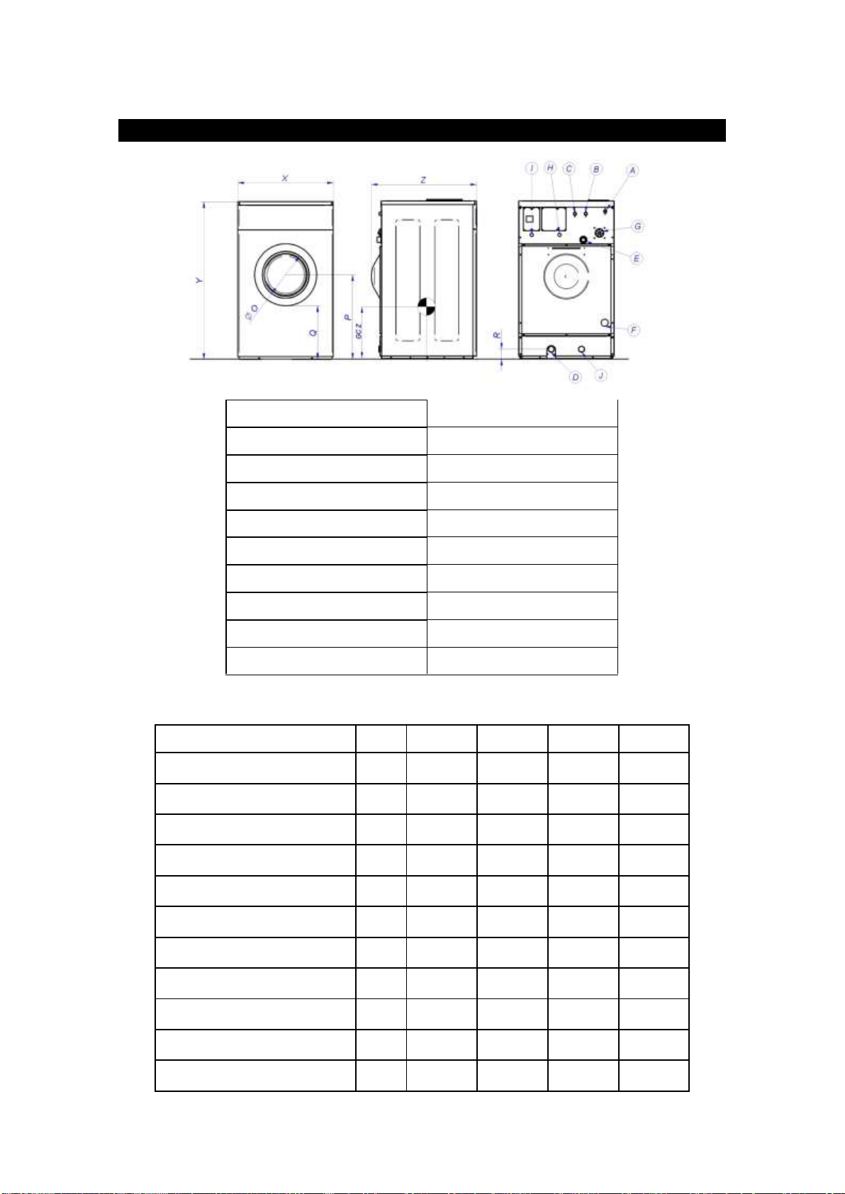
Main Dimensions
A (Cold water input)
29-58 psi (2-4 bar)
B (Hot water input)
29-58 psi (2-4 bar)
C (Aux water input)
29-58 psi (2-4 bar)
D (Drainage)
E (Steam output)
F (Steam input)
29-58 psi (2-4 bar)
G (Dispenser inlet)
H (Dispenser electric hose input)
I (Main electric hose input)
J (Drainage Nº2 –optional)
GROUP A (High spin floating washing machines)
MODEL
Unit
EWH-25
EWH-30
EWH-40
EWH-60
M (Drum diameter)
mm
Inch
532
20.94
620
24.41
700
27.56
770
30.31
N (Drum depth)
mm
Inch
425
16.73
430
16.93
470
18.5
530
20.86
O (Entrance diameter)
mm
Inch
290
11.41
373
14.7
373
14.7
373
14.7
P (Distance center of the drum)
mm
Inch
630
24.8
695
27.36
742
29.21
850
33.46
Q (Distance to the door)
mm
Inch
408
16.06
427
16.81
474
18.66
610
24.02
R (Drainage position)
mm
Inch
80
3.15
80
3.15
80
3.15
100
3.94
X (Width)
mm
Inch
692
27.24
790
31.10
885
34.84
979
38.54
Y (Height)
mm
Inch
1160
45.67
1300
51.18
1410
55.51
1562
61.5
Z (Depth)
mm
inch
825
32.48
870
34.25
915
36.02
1042
41.02
GC Y (Gravity centre)
mm
inch
424
16.69
398
15.67
464
18.27
503
19.8
GC Z (Gravity centre)
mm
inch
577
22.72
651
25.63
702
27.64
773
30.43
GR A-B-C

GROUP B (Fast spin rigid washing machines)
MODEL
Unit
EWR-25
EWR-30
EWR-40
EWR-60
M (Drum diameter)
mm
Inch
532
20.94
620
24.41
620
24.41
700
27.56
N (Drum depth)
mm
Inch
425
16.73
430
16.93
580
22.83
670
26.38
O (Entrance diameter)
mm
Inch
290
11.41
373
14.7
373
14.7
373
14.7
P (Distance center of the drum)
mm
Inch
630
24.8
695
27.36
695
27.36
742
29.21
Q (Distance to the door)
mm
Inch
408
16.06
427
16.81
427
16.81
474
18.66
R (Drainage position)
mm
Inch
80
3.15
80
3.15
80
3.15
100
3.94
X (Width)
mm
Inch
692
27.24
790
31.10
790
31.10
885
34.84
Y (Height)
mm
Inch
1160
45.67
1300
51.18
1300
51.18
1410
55.51
Z (Depth)
mm
inch
825
32.48
870
34.25
1040
40.94
1100
43.31
GC Y (Gravity centre)
mm
inch
425
16.73
419
16.5
510
20.08
638
25.12
GC Z (Gravity centre)
mm
inch
485
19.09
518
20.4
551
21.7
667
25.26
GROUP C (Standard spin rigid washing machines)
MODEL
Unit
EWS-25
EWS-30
EWS-40
EWS-60
EWS-80
M (Drum diameter)
mm
Inch
620
24.41
620
24.41
700
27.56
770
30.31
860
33.86
N (Drum depth)
mm
Inch
330
12.99
430
16.93
470
18.5
530
20.86
600
23.62
O (Entrance diameter)
mm
Inch
373
14.7
373
14.7
373
14.7
373
14.7
560
22.05
P (Distance center of the drum)
mm
Inch
568
22.36
568
22.36
654
25.75
654
25.75
733
28.86
Q (Distance to the door)
mm
Inch
310
12.20
310
12.20
396
15.59
396
15.59
373
14.7
R (Drainage position)
mm
Inch
135
5.31
135
5.31
95
3.74
135
5.31
135
5.31
X (Width)
mm
Inch
719
28.31
719
28.31
788
31.02
885
34.84
979
38.54
Y (Height)
mm
Inch
1177
46.34
1177
46.34
1321
52.00
1321
52.00
1428
56.22
Z (Depth)
mm
inch
738
29.06
853
33.58
895
35.24
1036
40.79
1166
45.91
GC Y (Gravity centre)
mm
inch
383
15.08
484
19.06
479
18.86
591
23.27
682
26.85
GC Z (Gravity centre)
mm
inch
511
20.12
524
20.63
546
21.5
541
21.3
635
25
Electrical Specifications
GROUP A-B (High spin floating washing machines and Fast spin rigid washing machines)
Electrical heating
230V-3~
230V-1N~
T+3x (mm²)
AWG
FUSE(A)
T+3x (mm²)
AWG
FUSE(A)
EWH-25/EWR-25
2.5
9
20
4
7
32
EWH-30/EWR-30
4
8
25
10
5
50
EWH-40/EWR-40
6
6
40
16
4
63
EWH-60/EWR-60
10
4
50
25
2
100
Hot water heating
Steam heating
230V-1N~
T+3x (mm²)
AWG
FUSE(A)
EWH-25/EWR-25
1.5
14
6
EWH-30/EWR-30
1.5
13
10
EWH-40/EWR-40
1.5
11
10
EWH-60/EWR-60
1.5
10
16
GROUP C(Standard spin rigid washing machines)
Electrical heating
230V-3~
230V-1N~
T+3x (mm²)
AWG
FUSE(A)
T+3x (mm²)
AWG
FUSE(A)
EWS-25
2.5
9
20
4
7
32
EWS-30
4
8
25
10
5
50
EWS-40
6
6
40
16
4
63
EWS-60
10
4
50
25
2
100
EWS-80
16
4
63
25
1
100
Hot water and
steam heating
230V-1N~
T+3x (mm²)
AWG
FUSE(A)
EWS-25
1.5
16
4
EWS-30
1.5
14
6
EWS-40
1.5
13
10
EWS-60
1.5
11
10
EWS-80
1.5
10
16

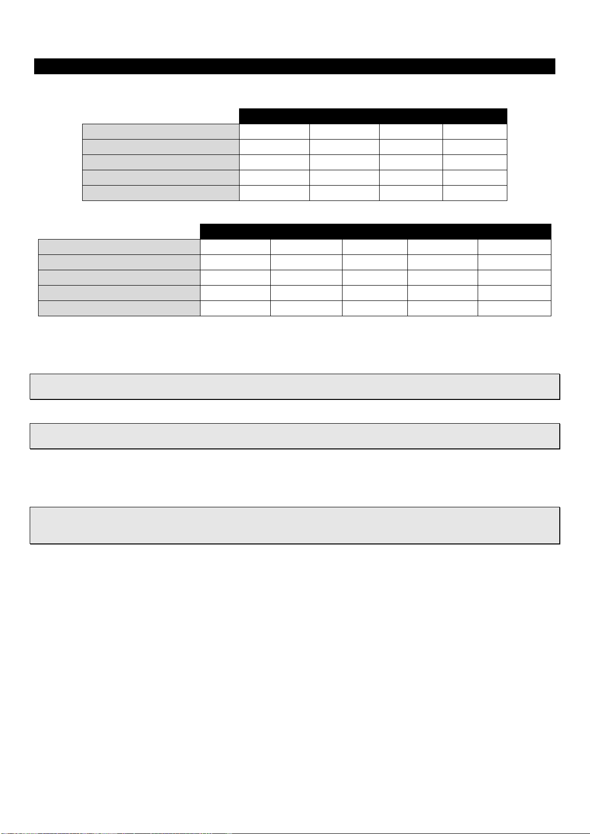
Rigid Washing Machines
GROUP B (Fast spin rigid washing machines)
MODEL
Unit
W1
W2
W3
W4
W5
W6
W7
W8
EWR-25
Inch
mm
19.69
500
16.42
417
4.72
120
3.78
96
3.89
99
6.10
155
27.24
692
31.13
791
EWR-30
Inch
mm
23.46
596
16.30
414
4.72
120
3.78
96
3.74
95
9.49
241
31.02
788
34.25
870
EWR-40
Inch
mm
23.46
596
18.07
459
4.72
120
3.78
96
8.03
204
9.9
251
31.02
788
40.73
1034
EWR-60
Inch
mm
27.24
692
21.38
543
4.72
120
3.78
96
8.01
203
10.1
257
34.8
884
44.23
1123
GROUP C (Standard spin rigid washing machines)
MODEL
Unit
W1
W2
W3
W4
W5
W6
W7
W8
EWS-25
Inch
mm
19.69
500
11.85
301
5.87
149
4.31
109.5
5.61
142.5
5.85
148.5
28.31
719
29.18
741
EWS-30
Inch
mm
19.69
500
12.01
305
9.13
232
4.31
109.5
6.79
172.5
5.85
148.5
28.31
719
33.78
858
EWS-40
Inch
mm
22.05
560
14.49
368
9.13
232
4.49
114
5.83
148
5.79
147
31.03
788
35.24
895
EWS-60
Inch
mm
24.41
620
15.24
387
11.81
300
5.20
132
7.68
195
6.22
158
34.81
884
40.95
1040
EWS-80
Inch
mm
27.56
700
19.29
490
11.81
300
5.49
139.5
7.64
194
6.22
158
38.54
979
44.96
1142

1
1. CONTENTS
1. CONTENTS...............................................................................................................................................................1
2. INTRODUCTION .......................................................................................................................................................2
3. IMPORTANT INSTRUCTIONS REGARDING SAFETY AND USE...........................................................................3
4. STANDARDS.............................................................................................................................................................5
5. TRANSPORT.............................................................................................................................................................5
6. CHARACTERISTICS OF THE PLACE OF INSTALLATION.....................................................................................5
7. HANDLING ................................................................................................................................................................5
8. INSTALLATION (ALL MODELS) ...............................................................................................................................6
8.1. Water connection ..............................................................................................................................................6
8.2. Steam connection..............................................................................................................................................6
8.3. Drainage............................................................................................................................................................6
8.4. Electrical connection .........................................................................................................................................7
8.5. Dispenser connection........................................................................................................................................7
9. INSTALLATION OF RIGID WASHING MACHINES (GROUPS B-C)........................................................................8
9.1. Using anchorage base ......................................................................................................................................9
9.2. Installation of the washer-extractor without anchorage base............................................................................9
9.2.1. Using expansion bolts...............................................................................................................................9
9.2.2. Using J-bolts............................................................................................................................................10
10. INSTALLATION OF SELF-SERVICE WASHING MACHINES (GROUP A-B-C) ...............................................11
10.1. Pay centre .......................................................................................................................................................11
10.2. Card.................................................................................................................................................................11
10.3. Coin.................................................................................................................................................................11

2
2. INTRODUCTION
Dear customer,
Thank you for the confidence you have placed in our product. We hope it meets your needs.
The guarantee does not cover damage to glass components, or consumables (seals, bulbs, etc.) nor damage to
insulation material or damage due to the incorrect installation of the appliance, or to inappropriate use, inadequate
maintenance or poor repair processes.
This appliance is subject to changes and modifications for its technical progress.
Retain This Manual In A Safe Place For Future Reference
American Dryer Corporation products embody advanced concepts in engineering, design, and safety. If this product
is properly maintained, it will provide many years of safe, efficient, and trouble free operation.
ONLY qualified technicians should service this equipment.
OBSERVE ALL SAFETY PRECAUTIONS displayed on the equipment or specified in the installation manual included
with the dryer.
The following “FOR YOUR SAFETY” caution must be posted near the dryer in a prominent location.
FOR YOUR SAFETY
Do not store or use gasoline or other flammable vapors and liquids in the vicinity of this or any other appliance.
POUR VOTRE SÉCURITÉ
Ne pas entreposer ni utiliser d’essence ni d’autres vapeurs ou liquides inflammables à proximité de cet appareil ou de
tout autre appareil.
We have tried to make this manual as complete as possible and hope you will find it useful. ADC reserves the right to
make changes from time to time, without notice or obligation, in prices, specifications, colors, and material, and to
change or discontinue models. The illustrations included in this manual may not depict your particular dryer exactly.
IMPORTANT
For your convenience, log the following information:
DATE OF PURCHASE__________________________________________ MODEL NO. ______________________
RESELLER’S NAME _____________________________________________________________________________
Serial Number(s) ________________________________________________________________________________
______________________________________________________________________________________________
______________________________________________________________________________________________
Replacement parts can be obtained from your reseller or the ADC factory. When ordering replacement parts from the
factory, you can FAX your order to ADC at (508) 678-9447 or telephone your order directly to the ADC Parts
Department at (508) 678-9000. Please specify the dryer model number and serial number in addition to the
description and part number, so that your order is processed accurately and promptly.

3
3. IMPORTANT INSTRUCTIONS REGARDING SAFETY AND USE
WARNING: To reduce the risk of electrical shocks
or injury when using the appliance, the basic
precautions should be observed, including the
following:
1-READ all the instructions prior to using the
appliance and KEEP THEM in an easily
accessible place for reference in the event
of doubt.
2- This appliance must be installed by an
Official or authorised Technical Assistance
Service. The installation, incorrect
adjustment, inappropriate maintenance or
use of the appliance may cause material
damages and injuries. Before
commissioning the appliance, carefully read
the instructions contained in this manual.
These contain important information about
the installation of the appliance
3- The incorrect installation, inappropriate
servicing, poor maintenance and/or
cleaning and modifications to the appliance
may cause damage to both the appliance
and the users.
4-Failure to comply with the given procedures
will result in the loss of cover under
guarantee.
5-Switch off the appliance in the event of
breakdown or faulty operation.
6-
7-Do not wash clothes which have been
previously treated, washed, soaked or
stained with petrol, dry cleaning solvents, or
other inflammable or explosive substances,
as these give off vapours which may catch
fire or explode.
8-Do not add petrol, dry cleaning solvents or
other inflammable substances to the
washing water. These substances give off
vapours which could catch fire or explode.
9-In some conditions, hydrogen gas may be
produced in a hot water system which has
not been used for more than two weeks.
HYDROGEN GAS IS EXPLOSIVE. If the
hot water system has not been used for a
while, before using the washing machine
turn on all the hot water taps and let the
water run for a few minutes. This will
release any accumulated hydrogen gas. As
the gas is inflammable, do not smoke or
use naked flames during this operation.
10-Do NOT allow children to play in or on the
appliance. Children should be strictly
supervised when in the vicinity of a machine
which is operating.
11-Remove the door from the appliance before
disposal or before leaving it out of service.
12-DO NOT TRY TO OPEN THE DOOR if the
drum is moving.
13-Do NOT install or store the appliance in the
open.
14-Do NOT try to force the controls.
15-Do not repair or replace parts of the
appliance or carry out any servicing unless
recommended to do so in the User
Instruction Manual. Make sure that you fully
understand the instructions and have the
necessary skills to carry out the operations
described.
16-Do NOT remove any safety device or modify
any components in the washing machine.
DO NO INSTALL components not
belonging to the machine in the appliance.
17-Failure to comply with any of the instructions
given in the Instruction Manual may result in
personal injury to the user. It is no possible
to provide for all possible situations and
contingencies with warnings about risk and
hazards. Therefore, any person involved in
the transportation, installation, use or
maintenance of the machine should always
employ common sense, caution and care.
18-Do NOT use the machine unless all the
covers and guards are correctly fitted and
secured.
19-The distributor (vendor) MUST correctly
instruct the user during commissioning.
20-Pour the correct doses of detergent, fabric
softener and bleach into the dispenser
drawer, as indicated by the manufacturer.
Heed tips concerning the treatment of
different materials given by the
manufacturers.
21-Remove any traces of detergent or liquids
from the dispenser drawer everyday. Never
use powdered or abrasive detergents for
cleaning; use only water and soap.
22-Clean the water inlet filters and the external
dispenser conducts once a month.

ENGLISH
4
23-Never clean the exterior by water injection;
functional parts of the machine could
damage.
24-If the washing machine is to be idle for long
periods, apply a coat of Vaseline oil to all its
stainless steel surfaces.
25-An annual general revision is recommended
WARNING! Repairs or work carried out by personnel
not belonging to the authorised Technical Service will
result in the loss of cover under guarantee.
CAUTION! Fire protection regulations must be strictly
observed.
WARNING! Before starting to connect the appliance,
check that the installation values match those given on
the appliance specification plate.
KEEP THESE INSTRUCTIONS SAFELY

ENGLISH
5
4. STANDARDS
All models comply to standard EN ISO 10472 concerning the safety requirements for industrial laundry machinery.
2006/42/EC Machinery Safety Directive
2006/95/EC Low Voltage
2004/108/EC Electromagnetic Compatibility Directive
UL Standard for Electric Clothes Washing Machines and Extractors; UL 2157 and CSA C22.2 No. 169
For models with a drum capacity of less than 120 dm3 (4.24 cu.ft):
Standards EN 60335-1 and EN 60335-2-7 concerning Electrical appliances.
Standards EN 55014, EN 61000-3-2 and EN 61000-3-3 on Electromagnetic compatibility.
For models with a larger capacity:
Standard EN 60204-1 concerning Electrical appliances.
Standards EN 61000-6-1, EN 61000-6-3 y EN 61000-3-1 on Electromagnetic compatibility.
5. TRANSPORT
When transporting the appliance, the following should be observed:
oCurrent regulations and laws
oRegulations concerning occupational risk prevention
oRegulations concerning safety during transport
Check the delivery is in good condition prior to receipt.
6. CHARACTERISTICS OF THE PLACE OF INSTALLATION
As established in current legislation, an omnipolar switch must be installed between the appliance and the mains
electricity supply with a minimum distance of 3 mm for each pole between contacts.
The washing machine must be firmly secured on the floor, which will support its weight and the residual force
generated while spinning.
The washing machine must be correctly levelled leaving spaces to make maintenance easier, 0.5 m on the side and 1
m at the rear.
WARNING! The stopcocks should be close to the appliance in an easily accessible location.
7. HANDLING
When handling the appliance, the following should be observed:
oCurrent regulations and laws
oRegulations concerning occupational risk prevention
- Safety clothing and gloves must be worn for protection against cuts and knocks and safety shoes should be
used to prevent against injury as a result of falling components.
- When handling and moving the appliance, appropriate tools and resources must be used.
- Any work to the interior of the appliance must be carried out by qualified and skilled personnel.
CAUTION! Inappropriate handling of the appliance may result in damage or injury.
ENGLISH
6
8. INSTALLATION (ALL MODELS)
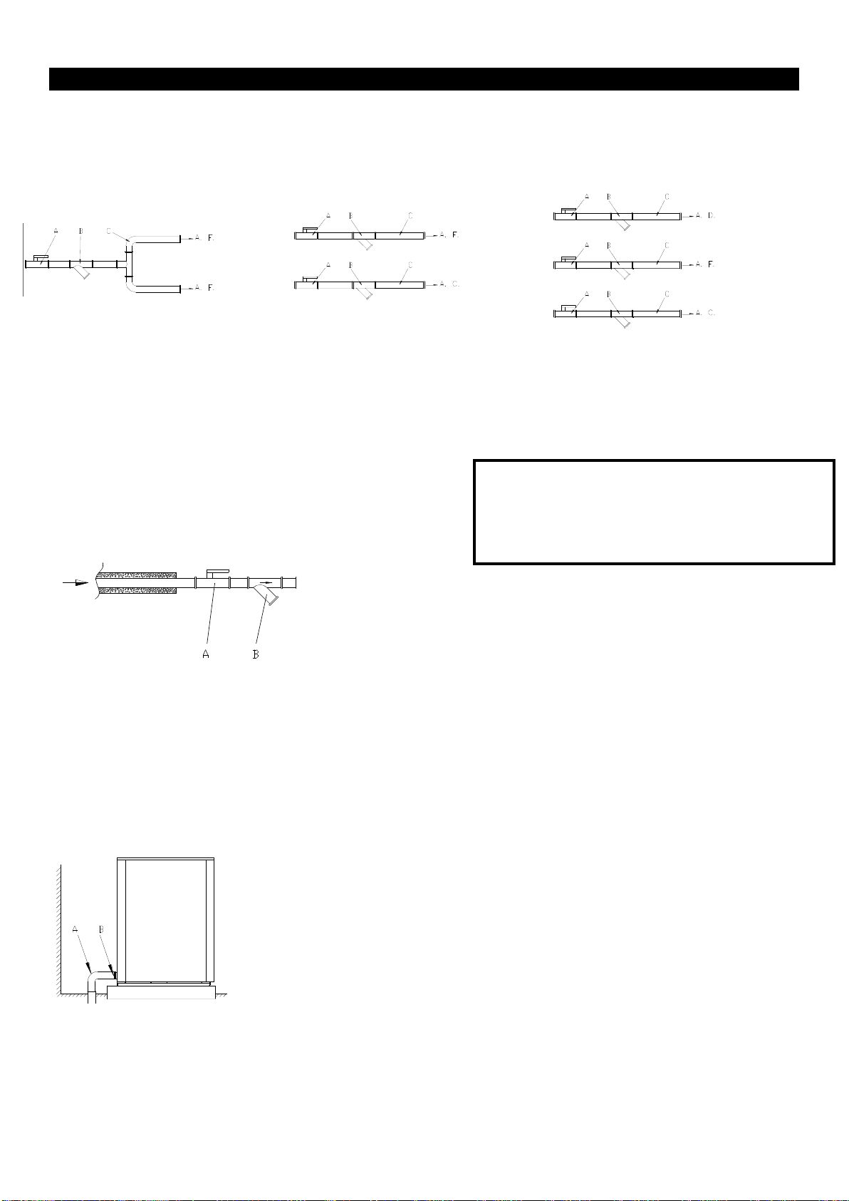
8.1.Water connection
If only cold water is available, connect as shown in figure 3. Where hot water is available, connect as shown in figure
4. If, in addition, decalcified water is available, connect as shown in figure 5
Required dynamic pressure: 2 ÷4 Kg/cm2.
VERY IMPORTANT: Bleed water circuit prior to installation and fitting filters.
8.2.Steam connection
If steam is available, the water will be heated by direct injection.
The connection diagram is shown in the figure.
Steam pressure: 2 ÷4 Kg/cm2.
VERY IMPORTANT: Bleed steam circuit prior to installation and fitting filters
After steam has been introduced into the machine for the first time, it is advisable for the steam hose nuts to be re-
tightened.
8.3.Drainage
Fix the drainage bend pipe as shown in the figure
Fig. 3
Fig. 4
Fig. 5
A=Stopcock
B=Filter
A=Stopcock B=Filter C=Hose A.C.=Hot water A.F.=Cold water A.D.=Decalcified water
A= Drainage pipe bend
B=Clamp
Warning!
Failure to fit the filters on the water and steam
inputs will result in loss of cover under
guarantee for the corresponding components

ENGLISH
7
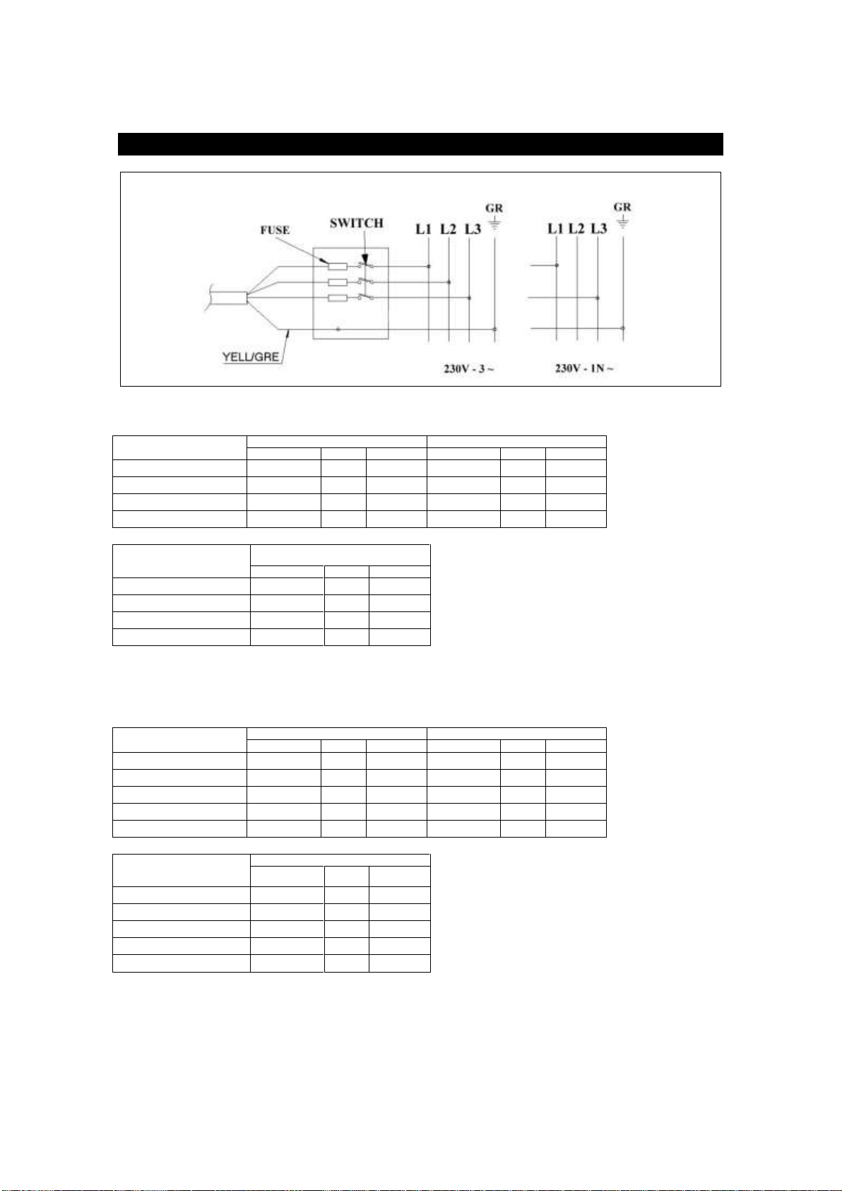
8.4.Electrical connection
WARNING: Risk of electrical shock
To access the connection strip, remove the switch cover and attach the hose cable to the rear panel. In large capacity
models (group D) the electrical connections are located in the rear cabinet, the circuit breaker must be set to “0” in
order to open the door
Connect the terminal strip and check that the connections correspond to the operating voltage.
Place an autonomous power switch (I) at the current input, with a minimum of 3 mm between contacts. Fit a 300mA,
type A, immediate response differential protection.
INSTRUCTIONS FOR CONNECTING THE EARTH
This appliance must be connected to an earthed metal, permanent wiring system, or an earth conductor should be
installed with the circuit conductors and connected to the earth discharge terminal or the appliance cable.
Connect the terminal strip and check that the connections correspond to the operating voltage.
Fit a 300mA, type A, immediate response differential protection.
The machine must be connected to earth.
If the voltage frequency is 60 Hz, change the drainage valve connection.
8.5. Dispenser connection
1: 230 V electrical signal. For dispenser 1 (prewash)
2: 230 V electrical signal. For dispenser 2 (wash)
3: 230 V electrical signal. For dispenser 3 (bleach)
4: 230 V electrical signal. For dispenser 4 (softener)
5: 230 V electrical signal. For dispenser 5 (ONLY PROGRAMMABLE MODELS)
6: 230 V electrical signal. For dispenser 6 (ONLY PROGRAMMABLE MODELS)
7: 230 V electrical signal. For dispenser 7 (ONLY PROGRAMMABLE MODELS)
ENGLISH
8
9. INSTALLATION OF RIGID WASHING MACHINES (GROUPS B-C)
EWR-25
EWR-30
EWR-40
EWR-60
Static floor load (kN - lb)
2,08 - 468
2,25 - 506
2,46 - 553
3,2 - 678
Dinamic floor load (Kn - lb)
0,5 - 112
0,6 - 135
0,9 - 202
1 - 225
Maximum vertical load (kN - lb)
2,58 - 580
2,85 - 641
3,36 - 755
4,2 - 944
Dinamic load frequency (Hz)
12
12
12
12
G factor
200
200
200
200
EWS-25
EWS-30
EWS-40
EWS-60
EWS-80
Static floor load (kN - lb)
2,17 - 478
2,39 - 526
2,81 - 619
3,40 - 749
4,73 - 1042
Dinamic floor load (Kn - lb)
0,3 - 66
0,35 - 77
0,45 - 99
0,6 - 132
0,8 - 176
Maximum vertical load (kN - lb)
2,47 - 538
2,74 - 603
3,26 - 718
4 - 881
5,53 - 1218
Dinamic load frequency (Hz)
12
12
12
12
12
G factor
100
100
100
100
100
Forces transmitted by the washing machine
WARNING! Rigid washing machines must not be installed on non-foundation floors without authorisation
from a technician familiar with the structure and resistance of the building.
Please check the weight of the machine plus the dynamic forces generated during spinning. The
manufacturer does not accept responsibility for any damage due to vibration in this type of installation.
The anchorage base IS SOLD SEPARATELY.
WARNING! RIGID MACHINES MUST BE ANCHORED TO THE FLOOR. Correct construction of the anchorage
to the floor is essential to ensure the correct working of the appliance and to prevent serious damage to the
structure of the machine

ENGLISH
9
9.1.Using anchorage base
Before mounting the base, a portion of the floor larger than the maximum area of the base must be lifted from the
floor, so that the hole depth dimensions are greater than those of the surface. Then, the anchor support must be
placed inside the hole with studs upwards, and the hole must be filled with concrete until the thread of the studs
protrudes over the concrete surface (figure 3), which must be smooth and flat. It is advisable to cover the threads with
adhesive tape so as to prevent the concrete from adhering to the surface.
It is extremely important to secure the anchor supports firmly by making sure the front part of these supports matches
up with the front part of the washing machine, and maintaining the minimum distance between the supports and the
wall or other appliances so as to facilitate maintenance.
Once the concrete has set properly, the washing machine can be placed in its final position by tightening the nuts and
the associated spacers in the bolts and making sure the machine is suitably levelled.
For the measurements of each appliance, please refer to the “Rigid washing machines” chart.
9.2.Installation of the washer-extractor without anchorage base
9.2.1.Using expansion bolts
Before anchoring the machine to the floor, make sure that its minimum resistance is equal or higher than 3600 psi
(25N/mm2).
First mark the points at which the holes are to be made, using the dimensions specified in the “Rigid washing
machines” chart.
Next make holes to a depth, at minimum, equal to 3,9 inch (100mm). Clean the holes with compressed air.
Place the washer-extractor in position over the holes, then insert the expansion bolts in the holes. Be sure to use M16
expansion bolts, and that they protrudes above the surface by 2,4 inch (60mm). Once in place, tighten the bolts until
the machine is securely fastened.
minimun resistance=25N/mm2(3600psi)

ENGLISH
10
9.2.2.Using J-bolts
Before anchoring the machine to the floor, make sure that its minimum resistance is equal or higher than 3600 psi
(25N/mm2).
First mark the points at which the holes are to be made, using the dimensions specified in the plans on page 12.
Next make holes to a depth, at minimum, equal to 3,9 inch (100mm). Make the holes big enough to insert the J-bolt
and clean using compressed air. Insert the J-bolts in the holes and secure using a suitable anchoring compound,
ensuring that the bolt protrudes above the surface by 2,4 inch (60mm). Be sure to use M16 J- bolts.
Place the washer-extractor in position above the bolts, and gradually tighten the nuts one after another until the
machine is securely fastened.
Check the condition of the J-bolts one week after installation.
ENGLISH
11
10. INSTALLATION OF SELF-SERVICE WASHING MACHINES (GROUP A-B-C)
10.1. Pay centre
Self-service machines are delivered with this configuration, i.e. they are ready for connection to a pay centre. The pay
centre receives an electrical signal from the washing machine informing of its availability and, at the same time, the
washing machine receives the signal that the correct money has been inserted and the programme may be run. The
price and currency settings are external to the washing machine and can therefore not be programmed. Please see
the user manual for details on self-service configuration.
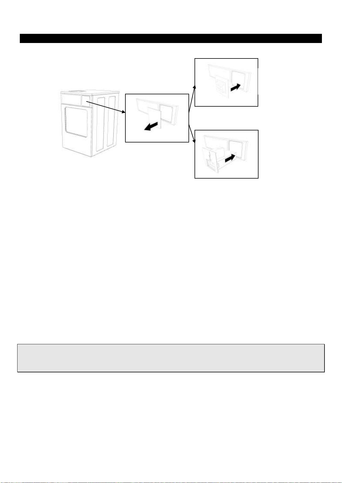
10.2. Card
If you have obtained the "card kit" it can be installed in the machine following the instructions supplied with the kit,
remove the cover to the right of the controls and insert the "card kit" in its place. To access the fastenings, remove the
top cover of the machine.
Once installed, the machine operates in almost the same way as the pay centre machine, prices and currency are
programmed on the card reader. Please see the user manual for details on self-service configuration.
10.3. Coin
If you have obtained the “coin kit” this can be installed in the machine by following the instructions supplied with the
kit. Remove the cover to the right of the controls and fit the "card kit" in its place. To access the fastenings, remove the
top cover of the machine.
Once installed, programme the currency and price settings for each programme. Please see the user manual for
instructions on self-service configuration.
¡WARNING! The installation of the different self-service kits involves working with electrical components.
Switch off the machine before any work.
Work carried out by personnel not belonging to the authorised Technical Service will result in the loss of
cover under guarantee.
Coin kit
Card kit
This manual suits for next models
12
Table of contents
Languages:
Other ADC EcoWash Dryer manuals


