Adelpia TGL198AW User manual

19” LCD Color Monitor Adelpia TGL198AW
1
Service
Service
Service
Horizontal Frequency
30KHz – 83KHz
TABLE OF CONTENTS
Description PageDescription Page
N
SAFETY NOTICE
ANY PERSON ATTEMPTING TO SERVICE THIS CHASSIS MUST FAMILIARIZE HIMSELF WITH THE CHASSIS
AND BE AWARE OF THE NECESSARY SAFETY PRECAUTIONS TO BE USED WHEN SERVICING ELECTRONIC
EQUIPMENT CONTAINING HIGH VOLTAGES.
Table Of Contents.......……..……..........................…........1
Revision List.….............……..........................……......2
Important Safety Notice.…………....................……......3
1. Monitor Specification..............................………........4
2. LCD Monitor Description…………………………….......5
3. Operation Instruction…………...............……...........6
3.1 General Instructions...........................…...........6
3.2 Control Button…………….…..............……...............6
3.3 Adjusting the Picture...........................…............8
4. Input/Output Specification............……………............11
4.1 Input Signal Connector.................…………................11
4.2 Factory Preset Display Modes....................................13
4.3 Power supply features………………………………..…13
4.4 Panel Specification.....……………………....................14
5. Block Diagram……....................…….………................16
5.1 Software Flow Chart….………………………....….......16
5.2 Electrical Block Diagram……..……………..….....…17
6.Schematic……………....................................…20
6.1 Main Board.…….....……..........................................20
6.2 Power Board..…………..……..................................24
6.3 Key Board..…………..……..................................26
7. PCB Layout..……………….......................................27
7.1 Main Board……………….........................................27
7.2 Power Board………....………...................................29
7.3 Key Board………………………………………………30
8. Maintainability………........................……...............31
8.1 Equipments and Tools Requirement………..............31
8.2 Trouble Shooting…….…………...............................32
9. White-Balance, Luminance adjustment.............38
10. Monitor Exploded View……...….……………............40
11. BOM List...……….....................................................42
CAUTION: USE A SEPARATE ISOLATION TRANSFOMER FOR THIS UNIT WHEN SERVICING
022-83718162
www.chinadse.org
022-83715667

19” LCD Color Monitor Adelpia TGL198AW
2
Revision List
Revision Date Revision History TPV Model
A00 Nov.-04-08 Initial Release T98MMANFX2UQHN
022-83718162
www.chinadse.org
022-83715667

19” LCD Color Monitor Adelpia TGL198AW
3
Important Safety Notice
Proper service and repair is important to the safe, reliable operation of all AOC Company Equipment. The service
procedures recommended by AOC and described in this service manual are effective methods of performing service
operations. Some of these service operations require the use of tools specially designed for the purpose. The special
tools should be used when and as recommended.
It is important to note that this manual contains various CAUTIONS and NOTICES which should be carefully read in
order to minimize the risk of personal injury to service personnel. The possibility exists that improper service methods
may damage the equipment. It is also important to understand that these CAUTIONS and NOTICES ARE NOT
EXHAUSTIVE. AOC could not possibly know, evaluate and advise the service trade of all conceivable ways in which
service might be done or of the possible hazardous consequences of each way. Consequently, AOC has not
undertaken any such broad evaluation. Accordingly, a servicer who uses a service procedure or tool which is not
recommended by AOC must first satisfy himself thoroughly that neither his safety nor the safe operation of the
equipment will be jeopardized by the service method selected.
Hereafter throughout this manual, AOC Company will be referred to as AOC.
WARNING
Use of substitute replacement parts, which do not have the same, specified safety characteristics may create shock,
fire, or other hazards.
Under no circumstances should the original design be modified or altered without written permission from AOC. AOC
assumes no liability, express or implied, arising out of any unauthorized modification of design.
Servicer assumes all liability.
FOR PRODUCTS CONTAINING LASER:
DANGER-Invisible laser radiation when open AVOID DIRECT EXPOSURE TO BEAM.
CAUTION-Use of controls or adjustments or performance of procedures other than those specified herein may result in
hazardous radiation exposure.
CAUTION -The use of optical instruments with this product will increase eye hazard.
TO ENSURE THE CONTINUED RELIABILITY OF THIS PRODUCT, USE ONLY ORIGINAL MANUFACTURER'S
REPLACEMENT PARTS, WHICH ARE LISTED WITH THEIR PART NUMBERS IN THE PARTS LIST SECTION OF
THIS SERVICE MANUAL.
Take care during handling the LCD module with backlight unit
-Must mount the module using mounting holes arranged in four corners.
-Do not press on the panel, edge of the frame strongly or electric shock as this will result in damage to the screen.
-Do not scratch or press on the panel with any sharp objects, such as pencil or pen as this may result in damage to the
panel.
-Protect the module from the ESD as it may damage the electronic circuit (C-MOS).
-Make certain that treatment person’s body is grounded through wristband.
-Do not leave the module in high temperature and in areas of high humidity for a long time.
-Avoid contact with water as it may a short circuit within the module.
-If the surface of panel becomes dirty, please wipe it off with a soft material. (Cleaning with a dirty or rough cloth may
damage the panel.)
022-83718162
www.chinadse.org
022-83715667

19” LCD Color Monitor Adelpia TGL198AW
4
1. Monitor Specifications
022-83718162
www.chinadse.org
022-83715667
19” LCD Color Monitor Adelpia TGL198AW
5
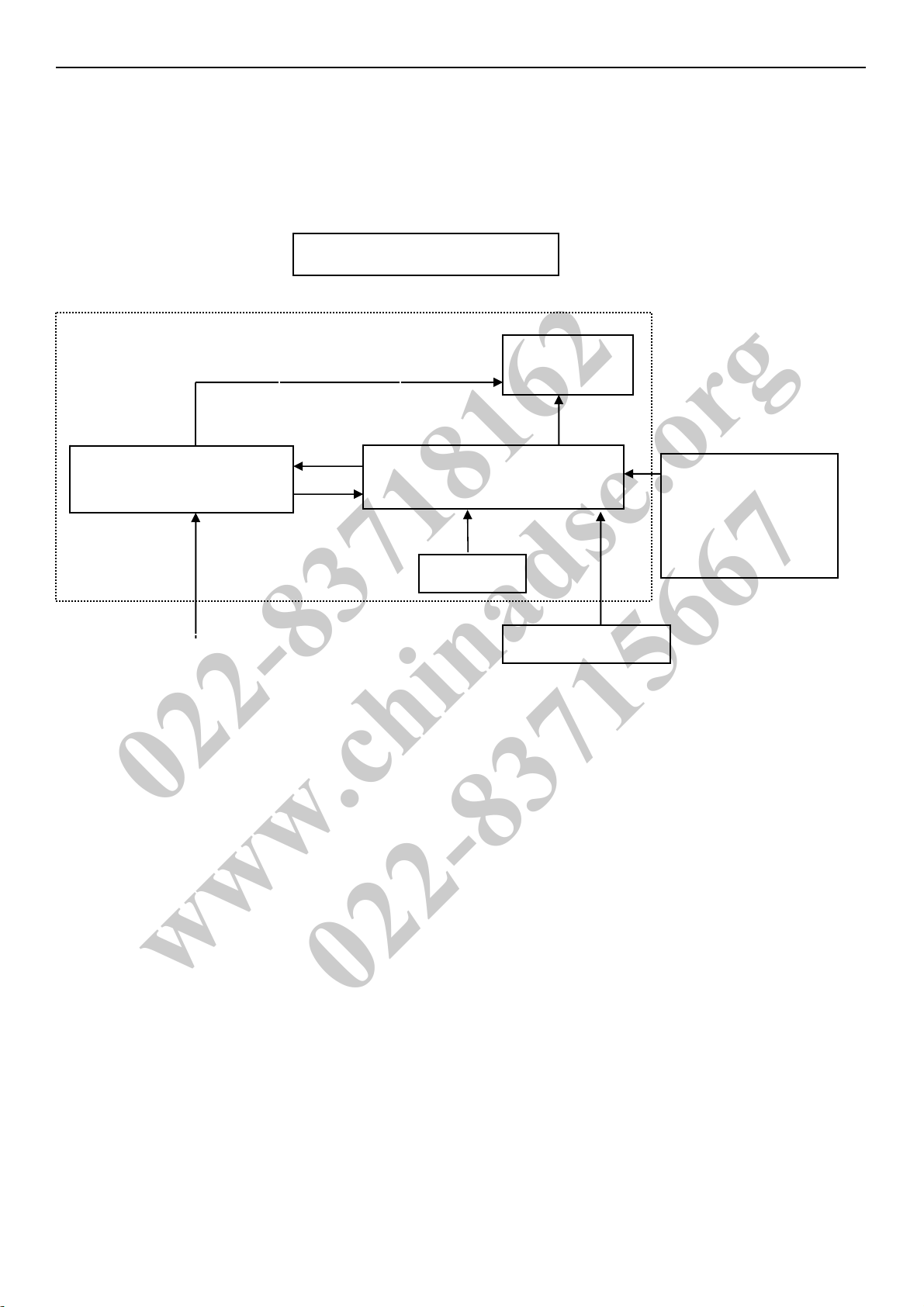
2. LCD Monitor Description
The LCD MONITOR will contain a main board, a power board and a key board which house the flat panel control logic,
brightness control logic and DDC.
The power board will provide AC to DC Inverter voltage to drive the backlight and the main board chips each voltage.
Monitor Block Diagram
Video signal, DDC
Power Board
(Contains Adapter, Inverter)
Flat Panel and
CCFL backlight
Main Board
Key board
RS232 Connector
For white balance
adjustment in factory
mode
HOST Computer
CCFL Drive.
AC IN
100V ~ 240V
022-83718162
www.chinadse.org
022-83715667

19” LCD Color Monitor Adelpia TGL198AW
6
3. Operating Instructions
3.1 General Instructions
Press the power button to turn the monitor on or off. The other control buttons are located in the bottom of the bezel. By
changing these settings, the picture can be adjusted to your personal preferences.
-The power cord should be connected.
-Connect the video cable from the monitor to the video card.
-Press the power button to turn on the monitor, the power indicator will light up.
3.2 Control Button
022-83718162
www.chinadse.org
022-83715667

19” LCD Color Monitor Adelpia TGL198AW
7
022-83718162
www.chinadse.org
022-83715667

19” LCD Color Monitor Adelpia TGL198AW
8
3.3 Adjusting the Picture
022-83718162
www.chinadse.org
022-83715667

19” LCD Color Monitor Adelpia TGL198AW
9
022-83718162
www.chinadse.org
022-83715667
19” LCD Color Monitor Adelpia TGL198AW
10
022-83718162
www.chinadse.org
022-83715667

19” LCD Color Monitor Adelpia TGL198AW
11
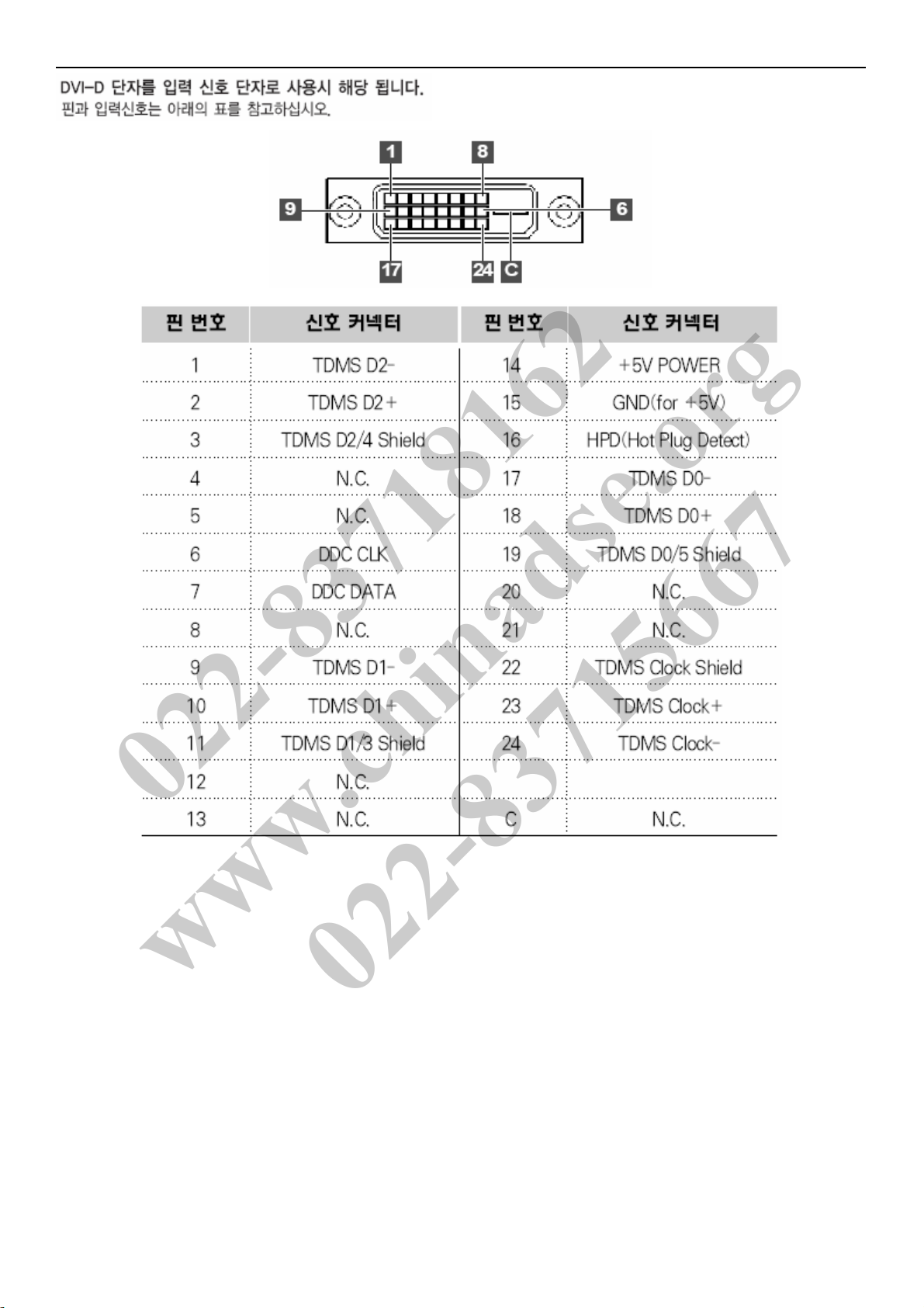
4. Input/Output Specification
4.1 Input Signal Connector
022-83718162
www.chinadse.org
022-83715667
19” LCD Color Monitor Adelpia TGL198AW
12
022-83718162
www.chinadse.org
022-83715667

19” LCD Color Monitor Adelpia TGL198AW
13
4.2 Preset operating modes
4.3 Power Supply Features
• A/C Line voltage range: 90 V - 264 V
• A/C Line frequency range: 50 Hz - 60Hz
• Current: 1.5 A max. at 100V/1.5A max. at 240V
• Peak surge current: < 55 A peak at 240 V AC and cold starting
• Leakage current: < 1.5 mA for power from PC-outlet
< 3.5 mA for power from Wall-outlet
• Power line surge: No adverse effects (no loss of information or defect) with a
maximum of 1 half wave missing per second
Power factor correction According to EN 61000-3-2
022-83718162
www.chinadse.org
022-83715667
19” LCD Color Monitor Adelpia TGL198AW
14
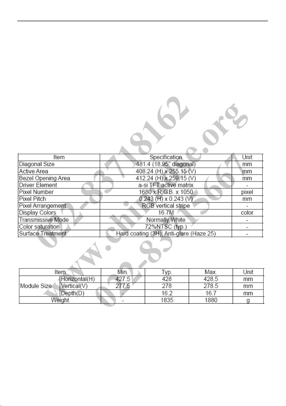
4.4 Panel Specification
Overview
M190Z1-L01 is a 19” wide TFT Liquid Crystal Display module with 4 CCFL Backlight unit and 30 pins
2ch-LVDS interface. This module supports 1680 x 1050 WSXGA+ mode and can display 16.7M colors.
The inverter module for Backlight is not built in.
Features
- Super Wide viewing angle.
- Super High contrast ratio
- Super fast response time
- High color saturation
- WSXGA+ (1680 x 1050 pixels) resolution
- DE (Data Enable) only mode
- LVDS (Low Voltage Differential Signaling) interface
- RoHS Compliance
4.4.1 General Specifications
4.4.2Mechanical Specifications
022-83718162
www.chinadse.org
022-83715667

19” LCD Color Monitor Adelpia TGL198AW
15
4.4.3 Electrical Characteristics
4.4.4 Optical Characteristics
022-83718162
www.chinadse.org
022-83715667

19” LCD Color Monitor Adelpia TGL198AW
16
5. Block Diagram
5.1 Software Flow Chart
1
2
N
Y
5
Y
N
10
Y
N
12
Y
N
7
Y
N
6
4
3
8
9
14
11
13
Y
N
15
Y
N
16
17
19
Y
N
18
022-83718162
www.chinadse.org
022-83715667

19” LCD Color Monitor Adelpia TGL198AW
17
1). MCU initialize.
2). Is the EEPROM blank?
3). Program the EEPROM by default values.
4). Get the PWM value of brightness from EEPROM.
5). Is the power key pressed?
6). Clear all global flags.
7). Are the AUTO and SELECT keys pressed?
8). Enter factory mode.
9). Save the power key status into EEPROM. Turn on the LED and set it to green color. Scalar initialize.
10). In standby mode?
11). Update the life time of back light.
12). Check the analog port, are there any signals coming?
13). Does the scalar send out an interrupt request?
14). Wake up the scalar.
15). Are there any signals coming from analog port?
16). Display "No connection Check Signal Cable" message. And go into standby mode after the message
disappears.
17). Program the scalar to be able to show the coming mode.
18). Process the OSD display.
19). Read the keyboard. Is the power key pressed?
022-83718162
www.chinadse.org
022-83715667

19” LCD Color Monitor Adelpia TGL198AW
18
5.2 Electrical Block Diagram
5.2.1 Scaler Board Block Diagram
U401
Scalar IC TSUMU58EHL-LF
(Include MCU, ADC, OSD)
·
D-Sub
Connector
(CN101)
H sync
V sync
RGB
LCD Interface
(CN301)
Key Board
Control
(CN402)
Crystal
(X401)
14.31818MHZ
DVI
Connector
(CN102)
022-83718162
www.chinadse.org
022-83715667

19” LCD Color Monitor Adelpia TGL198AW
19
5.2.2 Power Board Block Diagram
EMI filter Bridge
Rectifier and
Filter
Start Circuit
R904, R905, R906
PWM
Control IC
Transformer
Feedback
circuit
Rectifier
Diodes
AC input
5V
16V
ON/OFF
Control
PWM
Control IC
Feedback
Circuit
OSC and
Output
DC
Convert
MOSFET
Q804, Q809
Over Voltage
protect
Lamp
ON/OFF
DIM
CN902
022-83718162
www.chinadse.org
022-83715667

19” LCD Color Monitor Adelpia TGL198AW
20
6. Schematic
6.1 Main Board
VCC3.3
DSUB_H 2
DSUB_R- 2
VGA_B+
C121
1000pF
VGA_G-
DDC1_SDA
R101
100R 1/16W 5%
R110 470R 1/16W 5%
R119 100R 1/16W 5%
候綼
U103
DSUB_R+ 2
U107
AZC099-04S
1
2
3 4
5
6
I/O1
GND
I/O2 I/O3
VDD
I/O4
R134 10R 1/16W 5%
DDC1_SCL
R112
75R 1/16W 5%
R139 6K8 1/16W 5%
FB105
300 OHM
R138
4K7 1/16W 5%
ESD_VC C
Q101
NC
R107
2K2 1/16W 5%
R130 10R 1/16W 5%
C120
NC
U103
AZC099-04S
1
2
3 4
5
6
I/O1
GND
I/O2 I/O3
VDD
I/O4
R127 10R 1/16W 5%
C103
22pF
FB108
300 OHM
DDC1_SCL2
DDC1_SCL
DSUB_G+ 2
R106
2K2 1/16W 5%
DDC2_SCL
R131 10R 1/16W 5%
DVI_HPD
R121
NC
候綼
U101
候綼
U105
C108
0.047uF
RX2P 2
DSUB_SOG 2
C110
0.047uF
R129 10R 1/16W 5%
DSUB_B- 2
DDC2_SDA
C102
0.047uF
DSUB_G- 2
D104
BAT54C
3
1
2
R111 100R 1/16W 5%
C116
NC
DSUB_5V
C105
5pF/50V
HDCP_CTRL2
V_Sy nc
DET_CABLE 2
VGA_G+
MVCC_1
DVI_HPD
C119
NC
C101
NC
RX1N 2
R116
75R 1/16W 5%
U104
AZC099-04S
1
2
3 4
5
6
I/O1
GND
I/O2 I/O3
VDD
I/O4
VGA_G-
RX1N
FB104
300 OHM
ESD_VCC
VGA_B+
R109 100R 1/16W 5%
C122
1000pF
C113
5pF/50V
R108
75R 1/16W 5%
DSUB_SCL VGA_PLUG
U101
NC / M2 4C 02-W MN6TP
1
2
3
45
6
7
8A0
A1
A2
VSSSDA
SCL
WP
VCC
R104 1K 1/16W 5%
R128 10R 1/16W 5%
R124
4K7 1/16W 5%
R140
NC
R114 100R 1/16W 5%
R137
4K7 1/16W 5%
RX0P
DVI_5V
ESD_VCC
H_Sy nc
R120 10K 1/16W 5%
DDC1_SDA2
C104
22pF
候綼
U107
VGA_G+
FB103
BEAD
1 2
C112
NC
C111
0.047uF
DDC1_SDA
R113
100R 1/16W 5%
R136
NC
ESD_VCC
DSUB_5V
C109
5pF/50V
C114
0.047uF
DSUB_SDA
DGND
D108
BAT54C
3
1
2
GND POWER
CN102
JACK
1
2
3
4
5
6
7
8
9
10
11
12
13
14
15
16
17
18
19
20
21
22
23
24
26
25
DAT2-
DAT2+
2/4shield
DAT4-
DAT4+
DDC SCL
DDC SDA
VSYNC
DAT1-
DAT1+
1/3shield
DAT3-
DAT3+
+5V
SYNC GND
HPD
DAT0-
DAT0+
0/5shield
DAT5-
DAT5+
clk shield
clk+
clk-
GND
GND
VGA_R+
RX1P 2
VGA_B- C106
0.047uF
U105
AZC099-04S
1
2
3 4
5
6
I/O1
GND
I/O2 I/O3
VDD
I/O4
ZD105
RLZ5.6B
DDC_WP
2
ZD104
RLZ5.6B
VGA_R-
DVI_5V
R125
4K7 1/16W 5%
FOR EMI
CMVCC
R123
NC
VGA_R-
DSUB_SCL
U106
AZC099-04S
1
2
3 4
5
6
I/O1
GND
I/O2 I/O3
VDD
I/O4
DVI_5V
RX2N 2
RXCN
VGA_PLUG
C115
0.1uF/16V
DDC_WP
2
R103 1K 1/16W 5%
R122
NC
R132 10R 1/16W 5%
RX0P 2
DDC2_SCL
RX1P
DSUB_SDA
VGA_B-
R115 100R 1/16W 5%
CN101
DB15
1
6
2
7
3
8
4
9
5
11
12
13
14
15
10
17 16
DSUB_5V
R118 100R 1/16W 5%
VGA_R+
D109
BAT54C
3
1
2
R133
10K 1/16W 5% C117
NC
RX2P
CMVCC
VGA_B+
R135 10K 1/16W 5%
候綼
U106
R126 10R 1/16W 5%
R117 100R 1/16W 5%
ESD_VCC
DSUB_V 2
F
NEW Q SERIES B
26Monday , May 26, 2008
<
称爹
>
2.0.INPUT
G2883-1-X-X-14-080526
OEM MOD EL Size
Rev
Date Sheet of
TPV MOD EL
PCB NAME
称爹
T P V ( Top Victory Electronics Co . , Ltd. )
Key Component
絬
隔
瓜
絪
腹
U102
NC / M2 4C 02-W MN6TP
1
2
3
45
6
7
8A0
A1
A2
VSSSDA
SCL
WP
VCC
H_Sy nc
RXCN 2
C124
0.1uF 16V
RXCP 2
RX0N
FB101
BEAD
1 2
R102 0R05 1/10W 5%
C107
1000pF
DDC2_SCL 2
V_Sy nc
RX2N
VGA_R+
RXCP
DDC2_SDA
VGA_G+
FB107
300 OHM
RX0N 2
C118
NC
DSUB_B+ 2
DDC2_SDA 2
R105 100R 1/16W 5%
FB102
BEAD
1 2
022-83718162
www.chinadse.org
022-83715667
Table of contents
Other Adelpia Monitor manuals


