AFFINIS GROUP SaniServ 704 User manual
SaniServ P.O. Box 1089 Mooresville, Indiana 46158
Operation Manual
Frozen Beverage Dispensers
SaniServ®
An AFFINIS GROUP Company
“Reliability from the team that Serves the Best”


Distributor Name: ______________________________________________________
Address: _____________________________________________________________
Phone: _______________________________________________________________
Date of Installation: ____________________________________________________
Model Number: ________________________________________________________
Serial Number: _________________________________________________________
Installer/Service Technician: _____________________________________________
SERVICE: Always contact your SaniServ dealer or
distributor for service questions or service agency
referral. If your SaniServ dealer or distributor cannot
satisfy your service requirements, he is authorized to
contact the factory for resolution.
Note: It is the Owner’s responsibility to maintain the
Service Record located on the inside rear cover of this
manual. An accurate record of service performed can
greatly expedite troubleshooting of problems and
significantly reduce repair costs.
PARTS: Always order parts from your SaniServ dealer
or distributor. When ordering replacement parts,
specify the part numbers, give the description of the
part, the model number and the serial number of the
machine.
WARRANTY: Remove the Check Test Start (CTS)
form and fill it out in its entirety. Return the original
(white) copy to SaniServ. The Dealer/Distributor retains
the second (yellow) copy and the Owner/Operator
retains the third (pink) copy.
The Manufacturer's Limited Warranty is printed on the
reverse side of the Owner/Operator copy.
TO VALIDATE THE WARRANTY, THE CTS FORM
MUST BE COMPLETED AND RETURNED TO THE
FACTORY WITHIN 30 DAYS OF INSTALLATION.
Note: The Check Test Start function must be
performed by a qualified technician.
WARRANTY INFORMATION i
IMPORTANT
STATEMENT OF INTENDED USE
All SaniServ Machines covered in this manual are designed for one specific end use - to
freeze and dispense frozen beverages.
SPECIFICATIONS
704 707 709 724
Width
Inches (mm) 20.4
(518) 14
(356) 17.0
(432) 26.0
(660)
Height
Inches (mm) 32.8
(832) 31
(787) 32.5
(826) 55.9
(1419)
Depth
Inches (mm) 33.6
(854) 24
(610) 28.6
(726) 30.8
(781)
Machine Weight
lb (kg) 310
(141) 159
(72) 207
(94) 501
(228)
Circuit Amps -
Minimum 25 15 20 15*
Circuit Amps -
Maximum 30 15 25 15*
714
17.0
(432)
58.1
(1477)
24.8
(629)
305
(139)
15
15
SPECIFICATIONS
*Amps per side - this machine has two independent refrigeration systems
ii
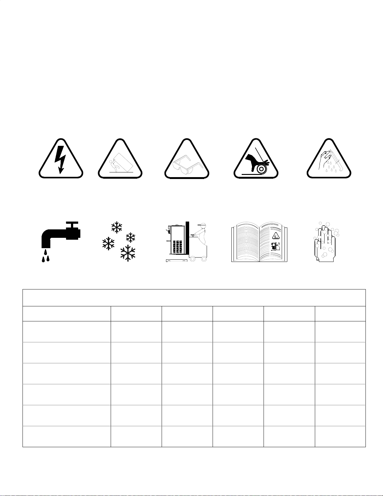
PICTOGRAM LEGEND
ELECTRICAL
SHOCK HAZARD TIP AND CRUSH
HAZARD HAND PINCH OR
ENTRAPMENT HAZARD SHARP MACHINE
PARTS HAZARD
CLEANOUT
OPERATION FROZEN
PRODUCT USE MECHANICAL
LIFT EQUIPMENT READ AND
UNDERSTAND WASH HANDS
BEFORE PROCEEDING
PROTECT EYES
SPLASH HAZARD

Table of Contents
Introduction and Installation..............................................................................................................1
Installer’s Preoperational Check .......................................................................................................3
Disassembly and Cleaning ...............................................................................................................3
Assembly and Lubrication.................................................................................................................8
Sanitizing .......................................................................................................................................12
Operation (Filling and Starting).......................................................................................................13
Helpful Hints ...................................................................................................................................14
Consistency Adjustment .................................................................................................................15
Routine Maintenance......................................................................................................................17
Troubleshooting..............................................................................................................................19
Troubleshooting Glossary...............................................................................................................20
Service Record ...............................................................................................................................21
TABLE OF CONTENTS iii

iv
Illustrations
Fig. 1 Leg Installation..................................................................................................................1
Fig. 2 Control Switch...................................................................................................................2
Fig. 3 Front Plates.......................................................................................................................2
Fig. 5 Do Not Insert Objects!.......................................................................................................3
Fig. 6 Restrictor Tube..................................................................................................................3
Fig. 7 Control Switch...................................................................................................................3
Fig. 8 Dispensing Product...........................................................................................................3
Fig. 9 Control Switch...................................................................................................................4
Fig. 10 Dispensing Product...........................................................................................................4
Fig. 11 Front Plate Assembly........................................................................................................4
Fig. 12 O-Ring Removal................................................................................................................4
Fig. 13 High Capacity Machine Front Plate Assembly ..................................................................5
Fig. 14 Large Barrel Machine Front Plate Assembly.....................................................................5
Fig. 15 Restrictor Tube..................................................................................................................5
Fig. 16 Dasher Assembly..............................................................................................................6
Fig. 17 Scraper Blade Removal....................................................................................................6
Fig. 18 Large Barrel Machine Dasher Assembly...........................................................................6
Fig. 19 High Capacity Machine Dasher Assembly ........................................................................6
Fig. 20 Drip Tray Assembly...........................................................................................................6
Fig. 21 Cleaning ALL Ports and Holes..........................................................................................7
Fig. 22 Dasher Lubrication............................................................................................................8
Fig. 23 Dasher Assembly..............................................................................................................8
Fig. 24 Scraper Blade Installation .................................................................................................9
Fig. 25 Scraper Blade Installation .................................................................................................9
Fig. 26 Scraper Blade Wear Mark.................................................................................................9
Fig. 27 Dasher Installation ............................................................................................................9
Fig. 28 Dasher Installation ............................................................................................................9
Fig. 29 Dasher with Blade (Front View).......................................................................................10
Fig. 30 Spigot Plunger Lubrication..............................................................................................10
Fig. 31 Front Plate Assembly......................................................................................................10
Fig. 32 Large Barrel Machine Front Plate Assembly...................................................................10
Fig. 33 Large Barrel Machine Front Plate Assembly...................................................................11
Fig. 34 Drip Tray Assembly.........................................................................................................11
Fig. 35 Restrictor Tube Lubrication.............................................................................................11
Fig. 36 Do Not Insert Objects!.....................................................................................................12
Fig. 37 Dispensing Product.........................................................................................................13
Fig. 38 MIXOUT Light .................................................................................................................13
Fig. 39 Mechanical Consistency Control.....................................................................................15
Fig. 40 Electronic Consistency Control .......................................................................................16
Fig. 41 Scraper Blade Wear Mark...............................................................................................17
Fig. 42 Drip Chute.......................................................................................................................17
Fig. 43 Clean Sharp Condenser Fins..........................................................................................17
Fig. 54 Spring Adjustment Mechanism .......................................................................................18
ILLUSTRATIONS

INTRODUCTION and INSTALLATION
ALWAYS USE A SUFFICIENT NUMBER OF PEOPLE
OR MECHANICAL LIFTING EQUIPMENT TO
PROTECT ALL PERSONNEL FROM PERSONAL
INJURY DURING THE REMAINING STEPS.
1. Raise the machine to install the four legs packed in
the mix pan or the four casters packed in a box on the
skid or on the front mounted drip tray. Be certain all
four are tight! Thread lock is suggested.
2. Carefully lower the machine to the floor and place it
where it will be installed.
3. Level the unit by turning the bottom part of each leg
clockwise or counterclockwise (Fig. 1). The machine
MUST be level to operate properly.
A MINIMUM 6” (152 MM) CLEARANCE MUST BE
MAINTAINED AT THE REAR AND SIDES OF THE
MACHINE FOR ADEQUATE VENTILATION.
ALWAYS CHECK ELECTRICAL SPECIFlCATIONS
ON THE DATA PLATE OF THE MACHINE. THE
DATA PLATE SPECIFICATIONS WILL ALWAYS
SUPERSEDE THE INFORMATION IN THIS MANUAL.
4. Electrical and refrigeration specifications are
located on the data plate on the rear panel of the
individual machines. Consult local authorities for
information regarding plumbing and electrical codes in
your area. Remove the left and right side panels for
power hook-up.
Note: All SaniServ machines should have their
own dedicated circuits to prevent low voltage
conditions caused by other operating equipment.
5. The water line connections on water-cooled
machines is located on the back side of the
machine. The IN/OUT lines are clearly marked and
equipped with 3/4” garden hose fittings.
FAILURE TO PROVIDE FOR PROPER EARTH
GROUND ACCORDING TO LOCAL ELECTRICAL
CODES COULD RESULT IN SERIOUS ELECTRICAL
SHOCK OR DEATH. DO NOT USE EXTENSION
CORDS. INSTALL THE PROPER SIZE WIRE FOR
THE REQUIRED MACHINE AMPS. BE CERTAIN TO
OBSERVE LOCAL CODES IN SELECTING WIRE OR
CORD SIZE AND TYPE.
DO NOT TURN MACHINE
ON UNTIL THE
INSTALLER’S PRE-
OPERATIONAL
CHECK SECTION IS
COMPLETE.
Installation
Fig. 1
Minimum
Clearance
4”(102 mm) for
This manual provides a general system description of the SaniServ Frozen Beverage Dispensers. It has been prepared
to assist in the training of personnel on the proper installation, operation, and maintenance of the machines.
Read and fully understand the instructions in this manual before attempting
to install, operate, or perform routine maintenance on the machines.
The following sections of the manual must be performed in sequence:
1. Installation 4. Assembly & Lubrication
2. Installer's Preoperational Check 5. Sanitizing & Operation
3. Disassembly & Cleaning 6. Consistency Adjustment
Introduction
PAGE 1
WARNING
WARNING
IMPORTANT

Installer’s Preoperational Check
THE FOLLOWING ITEMS MUST BE PERFORMED BEFORE ATTEMPTING TO OPERATE THE EQUIPMENT:
INSTALLERS PREOPERATIONAL CHECK
PAGE 2
Fig. 3a
High Capacity
Machine Front
Plate
Fig. 3c
Machine Front
Plate 5” (127 mm)
Barrel
Fig. 3b
Large Barrel
Machine Front
Plate
Fig. 2
Control Switch
AUTO
CLEANOUT
O
F
F
O
F
F
1. Make certain that proper electrical connections have
been made. Plug power cord into power outlet.
2. Set each control switch (Fig. 2) to the “CLEANOUT”
position momentarily to verify the direction of rotation of
the dasher. Looking at the front of the machine, the
dasher should rotate counter-clockwise.
3. Set each control switch to the “OFF” position.
In the event the dasher turns clockwise, STOP and
do not proceed any further. On three-phase units,
reverse the polarity.
WARNING
UNDER NO CIRCUMSTANCES SHOULD THE UNIT
BE OPERATED IN THE “AUTO” POSITION FOR MORE
THAN THREE MINUTES WITH EMPTY FREEZING
CYLINDERS . DOING SO WILL RESULT IN DAMAGE
TO THE MACHINE.
CAUTION
Emptying Machine
Prior to the disassembly and cleaning of parts, the
machine must be emptied of product. Use the following
procedures (Steps 1 through 3). If this is first time
operation, disregard these steps.
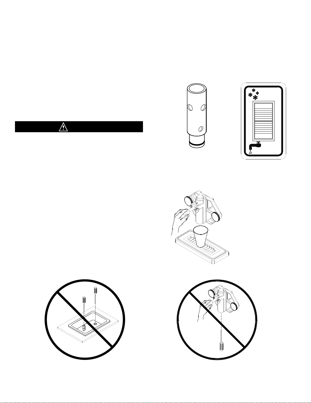
DO NOT INSERT ANY OBJECTS OR TOOLS (FIG. 5)
INTO THE MIX INLET HOLE, RESTRICTOR TUBE
HOLE, OR FRONT PLATE DISPENSING HOLE WHILE
THE MACHINE IS RUNNING. DAMAGE TO THE
MACHINE OR PERSONAL INJURY MAY RESULT
1. For Models 108 & 704, remove the restrictor tube (Fig.
6) from the mix inlet holes and lay in the bottom of the mix
pans. Note: Some units have these tubes welded in
place
2. Set each control switch (Fig. 7) to the “CLEANOUT”
position and dispense all product from the freezing
cylinder by pulling downward on the spigot handle
(Fig. 10) to empty the machine.
3. Set each control switch to the “OFF” (center) position.
Close the spigot handle(s) (Fig. 8) before proceeding to
cleaning.
CONSULT YOUR LOCAL HEALTH AGENCY FOR LOCAL CLEANING AND SANITIZING REQUIREMENTS.
This unit does not come pre-sanitized from the factory. Before serving product, the dispenser must be disassembled,
cleaned, lubricated, and sanitized. Please be aware that these instructions are general guidelines. Cleaning and sanitizing
procedures must conform to local Health Authority requirements.
DISASSEMBLY and CLEANING
Fig. 6
Model 108 & 704
Restrictor Tube
Fig. 8
Dispensing Product
Fig. 7
Control Switch
Disassembly and Cleaning
AUTO
CLEANOUT
O
F
F
O
F
F
Fig. 5
Do Not Insert Objects or Tools
CAUTION
PAGE 3
DISASSEMBLY and CLEANING
Disassembly and Cleaning Procedure
1. Fill the machine with cold water and set each control
switch (Fig. 9) to the “CLEANOUT” position. DO NOT
use hot water which could damage the machine. Let the
machine agitate 1 to 2 minutes, then drain the water by
pulling downward on the spigot handle (Fig. 10). Repeat
the above procedure as necessary to make certain all
product is removed from the machine. After the machine
is empty, set each control switch to the “OFF” position.
2. Prepare a suitable detergent and water solution at a
temperature of approximately 125°F. (52°C.) to 130°F.
(55°C.). For best cleaning results select a concentrated
anti-bacterial dishwashing detergent containing
biodegradable anionic and nonionic surfactants. Avoid
detergents containing phosphates. DO NOT use an
abrasive detergent on any part of the dispenser.
DO NOT USE HOT WATER.
DOING SO MAY DAMAGE THE MACHINE.
3. Make certain that the machine is “OFF”. Fill the mix
pan(s) with the cleaning solution. Clean the mix pan(s)
thoroughly with a brush as the solution drains into the
freezing cylinder(s). Clean the mix inlet tube(s) and the
restrictor tube holes with the brush provided.
4. Set the control switch to the “CLEANOUT” position
and agitate for approximately 1 to 2 minutes and then
drain the water by pulling down on the spigot handle.
After the unit is empty, set each control switch to the
“OFF” position.
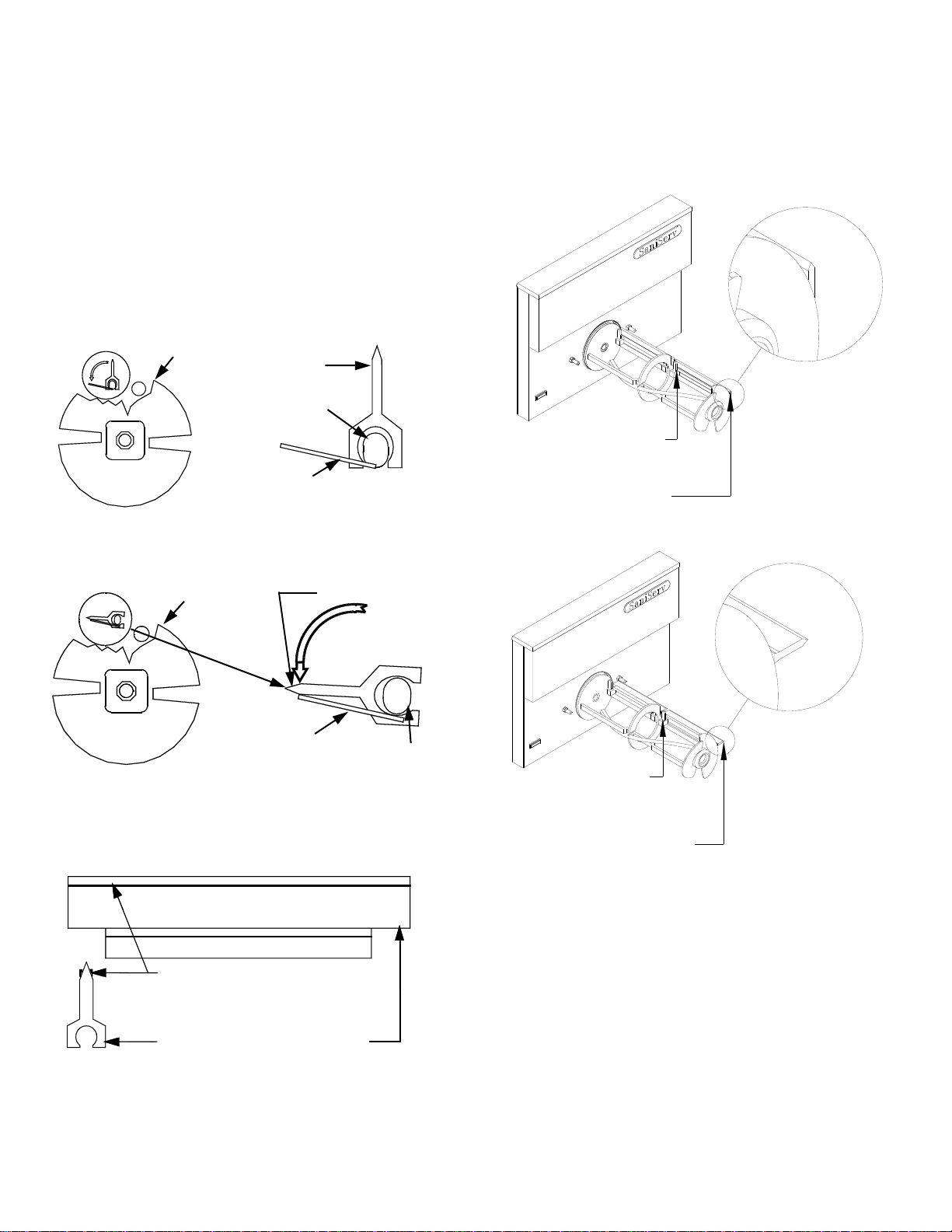
DO NOT USE ANY TOOLS OR SHARP OBJECTS TO
REMOVE ANY O-RINGS FROM THIS MACHINE.
SHARP OBJECTS WILL DAMAGE THE O-RINGS.
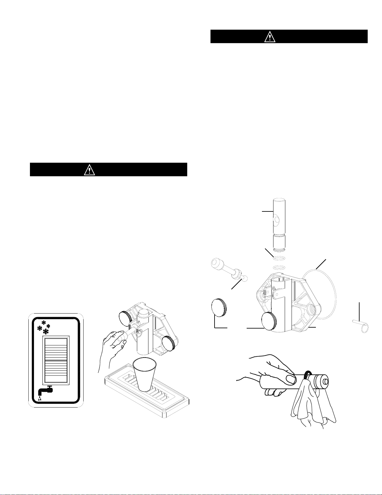
5. Remove the front plate by turning the black plastic
knobs in a counterclockwise direction (Fig. 11).
Disassemble the front plate in the following manner:
a. Remove the faspin and spigot handle.
b. Remove the front plate o-ring.
c. With the spigot handle removed, push the spigot
plunger out the top of the front plate and remove all
lubricant from the spigot plunger.
d. Remove the o-rings from the spigot plunger by
grasping the part with one hand and with a dry
cloth in the other hand, squeeze the o-ring upward.
When a loop is formed, grasp the o-ring with the
other hand and roll it out of its groove and off the
spigot plunger (Fig. 12).
Fig. 10
Dispensing Product Fig. 12
O-Ring Removal
Spigot Plunger
Faspin
Spigot
Handle
Front Plate
Front Plate O-ring
DO NOT LUBRICATE
Spigot Plunger
O-rings
Front Plate
Knobs
Fig. 9
Control Switch
Fig. 11
Front Plate Assembly
AUTO
CLEANOUT
O
F
F
O
F
F
CAUTION
CAUTION
PAGE 4

DISASSEMBLY and CLEANING
6. The front plate for the high capacity series machines
(Fig. 13) is disassembled in the same manner as the front
plate shown in Fig. 11.
7. Disassemble the large barrel machine front plate
(Fig. 14) in the following manner:
a. Remove the four front plate knobs.
b. Remove front plate from machine
c. Remove front plate O-Ring
d. Open spigot handle.
e. Clean spigot openings with the cleaning brush.
(Fig. 15)
8. Remove the restrictor tube from the mix pan and
remove the o-ring in the same manner used to remove
the o-rings from the spigot plunger. Clean the inside of
the tube with the brush provided.
Fig. 13
High Capacity Machine
Front Plate Assembly
Fig. 14
Large Barrel Machine
Front Plate Assembly
Spigot Plunger
Spigot Plunger
O-rings
Front Plate
O-ring
Spigot Handle
Knob
Front Plate
FasPin
Front Plate
O-ring
Spigot Nut
O-Ring
Spigot
Assembly
Front Plate
Knob x 4
Fig. 15
Cleaning Large Barrel
Front Plate Assembly
PAGE 5

10. Remove the mix pan lid, drip tray and drip tray
insert (Fig. 20).
9. Remove the dasher assembly (Fig. 16) being careful
not to damage the scraper blades, then disassemble in
the following manner:
a. Remove and take apart the rear seal assembly.
b. Remove the stator rod from the dasher.
c. Remove the blades from the dasher (Fig. 16)
by first rotating blade upward (Fig. 17) and then
Dasher Front
View Scraper Blade
Blade Support
Tab
Support
Rod
Blade Support
Tab
Support
Rod
Dasher Front
View
Scraper Blade
Fig. 20
Drip Tray Assembly
Fig. 17
Scraper Blade Removal
Fig. 16
Dasher Assembly
DISASSEMBLY and CLEANING
Dashers in the high capacity and large barrel
machines have no stator rods, but both have front
bushings (Fig. 18 and Fig. 19).
Rear Seal
Rear Bearing
Front Bushing
Scraper Blade
Dasher
Scraper Blade
Rear Seal
Rear Bearing
Dasher
Stator Rod
Rear Seal
Front Bushing
Dasher
Scraper Blade
Rear Bearing
Fig. 19
High Capacity Machine
Dasher Assembly
Fig. 18
Large Barrel Machine
Dasher Assembly
Drip Tray Insert
Drip Tray
Drip Tray Support
Remains Attached
To Machine Front
PAGE 6

12. Place all parts in a three partition sink filled with the
following solutions:
a. In one partition, detergent solution diluted to the
manufacturer’s suggested concentration for use.
b. In a second partition, clear rinse water.
c. In a third partition, sanitizing rinse solution which
will produce a 200 parts per million (PPM) Chlorine
residual or whatever Chlorine residual is required by
your Local Health Authority.
13. Use the brushes to clean all holes and ports in the
parts (Fig. 21).
DO NOT use an abrasive detergent
14. After thoroughly washing the parts in the detergent
solution, rinse them in the clear rinse water. Place the
parts in the sanitizing solution for at least five minutes or
whatever your Local Health Authority requires, and then
air dry the parts before for assembly and lubrication.
DO NOT ALLOW THE PARTS TO SOAK IN
SANITIZER FOR SEVERAL HOURS.
DO NOT WIPE THE PARTS DRY - AIR DRY ONLY.
15. The remainder of the machine including the mix pan
and freezing cylinder must be cleaned in place using a
mild detergent solution followed by a clear rinse. Clean
the exterior with a damp cloth.
DO NOT use an abrasive cleaner on the exterior of the
machine or on any of the panels (guards).
WHEN CLEANING THE MACHINE, DO NOT ALLOW
EXCESSIVE AMOUNTS OF WATER AROUND ANY
ELECTRICALLY OPERATED COMPONENTS OF THE
MACHINE. ELECTRICAL SHOCK OR DAMAGE TO
THE MACHINE MAY RESULT.
11. For best cleaning results select a concentrated
anti-bacterial dishwashing detergent containing
biodegradable anionic and nonionic surfactants.
NOTE: Avoid detergents containing phosphates.
WEAR SAFETY GLASSES
- DO NOT SPLASH
DETERGENT SOLUTION
IN EYES
Be certain to follow the
manufacturer’s mixing
instructions when adding
the dishwashing detergent
concentrate to water.
DISASSEMBLY and CLEANING
CAUTION
Fig. 21
Clean ALL Holes and Ports
with Brushes
CAUTION
CAUTION
CAUTION
CAUTION
WARNING
PAGE 7

1. Lubricate and assemble the dasher assembly in the
following manner:
a. Apply a generous amount of lubricant to the
shoulder of the dasher and the area of the shaft
where the white plastic portion of the assembled
rear seal contacts the shaft (Fig. 22). This is easily
performed by running a 1/4” (6 mm) bead of
lubricant around the shoulder of the dasher.
b. Lubricate the two areas of the stator rod (Fig. 22a)
and slide the stator rod into the dasher (Fig. 23).
Make certain that the end of the stator rod is
inserted into the hole at the rear of the dasher.
c. Assemble and install the rear seal with the rubber
portion toward the rear of the freezing cylinder as
indicated in Fig. 23.
DO NOT LUBRICATE THE RUBBER PORTION OF
THE REAR SEAL. LUBRICATION ON THE REAR
SEAL WILL DAMAGE THE MACHINE.
d. Install the o-ring on the rear of the dasher shaft.
DO NOT LUBRICATE DASHER O-RINGS
e. Install the front bearing on the dasher of the large
barrel and the high capacity machines.
Use a food grade lubricant* ONLY. Haynes Lubri-Film (SaniServ part number 1150) is recommended and is available
from the factory or your local authorized SaniServ dealer or distributor. Lubrication must be performed daily.
* The SaniServ recommended product is a colorless to white, odorless, tasteless food contact lubricant accepted by the
United States Food and Drug Administration (FDA) with a USDA rating of H1 and certified for food contact by NSF
International.
ASSEMBLY and LUBRICATION
Fig. 22a
Stator Rod and Dasher Lubrication
Assembly and Lubrication
Fig. 22c
Large Barrel Machine
Dasher Assembly
Lubricate Shaded
Areas Including
Rear of Shoulder
Lubricate
Shaded
Areas
Lubricate Shaded
Areas Including
Rear of Shoulder
Scraper
Blade
Dasher
Stator Rod
Rear Bearing
Rear Seal
Fig. 23
Dasher Assembly
Fig. 22b
High Capacity Machine
Dasher Assembly
CAUTION
PAGE 8
f. Install the scraper blades onto the dasher
assembly by holding the blades perpendicular to
the tabs (Fig. 24) and then snapping them over the
flat area of the support rod. Then rotate the blades
downward in a counterclockwise direction as
viewed from the front of the dasher (Fig. 25). BE
CERTAIN THAT THE SCRAPER BLADES REST
UPON THE DASHER TABS ON ALL DASHERS
EXCEPT HIGH CAPACITY MACHINE DASHERS.
THOSE BLADES REST UPON PINS.
Note: Reverse the blades at each cleaning to maintain
sharpness. In addition, the blades are equipped
with a wear mark (Fig. 26). When the blade is
worn to this wear mark, it must be replaced.
Blade Support
Tab
Support Rod
Dasher Front View
Scraper Blade
Dasher Front
View
Blade Support
Tab Support Rod
Scraper Blade
Rotate Down
Counter
Clockwise
Scraper Blade Wear Mark
End
View Side
View
ASSEMBLY and LUBRICATION
Fig. 25
Scraper Blade Installation
Fig. 24
Scraper Blade Installation
Fig. 26
Scraper Blade Wear Mark
g. Insert the dasher assembly into the freezing
cylinder as far as possible (Fig. 27) being careful
not to damage the scraper blades. Damage will
occur to the scraper blades and the dispenser will
not operate properly if the scraper blades are
installed facing in a clockwise direction (Fig. 28).
Note: The stator rod has been deleted from Fig. 29 and
Fig. 30 for clarity only. The stator rod must be installed
for proper machine operation.
h. While maintaining force against the dasher, rotate it
slowly until the tongue of the dasher engages the
groove in the drive system at the rear of the
cylinder. The outer most portion of the dasher
should be recessed approximately 1/4” (6 mm) to
3/8” (10 mm) inside the freezing cylinder. No part
of the dasher should extend outside the cylinder.
Scraper blades should be visible, extending
approximately 1/8” (3 mm) beyond the dasher
(Fig. 29).
Fig. 27
Dasher Installation
CORRECT
Blades
Resting On Tabs
Blades Pointing In A
Counterclockwise
Direction
Fig. 28
Dasher Installation
Blades Should
Rest On Tabs
Blades Should Not Point
In A Clockwise Direction
INCORRECT
PAGE 9

2. Lubricate and assemble the front plate assembly in
the following manner:
a. Install the two o-rings on the spigot plunger by
rolling them onto the plunger. Seat the o-rings in
the grooves. Be certain that they are not twisted.
Smooth the lubricant into the grooves and over
the sides of the plunger assembly (Fig. 30).
b. Slide the lubricated spigot plunger into the front
plate (Fig. 31) making certain that the spigot handle
slot is aligned to the front.
C. Insert the spigot handle and secure with the faspin.
d. Install the front plate o-ring.
DO NOT LUBRICATE THE FRONT PLATE O-RING
e. Secure the front plate assembly with the two
plastic knobs. Simultaneously, turn the knobs in a
clockwise direction. Tighten the knobs evenly.
DO NOT tighten one knob all the way down and
then the other. Doing so may result in front plate
breakage. Only moderate force is required.
DO NOT over tighten. Close the spigot plunger.
3. The high capacity machine front plate is lubricated
and assembles in the same manner.
4. Assemble the large barrel machine front plate in the
following manner:
Fig. 29
Dasher with Blade (Front View)
Spigot Plunger
Faspin
Spigot
Handle
Front Plate
Front Plate O-ring
DO NOT LUBRICATE
Spigot Plunger
O-rings
Front Plate
Knobs
Fig. 31
Front Plate
Assembly
Fig. 32
Large Barrel Machine
Front Plate Assembly
ASSEMBLY and LUBRICATION
Approximately 1/8 inch
Exposed
Fig. 30
Spigot Plunger Lubrication
Lubricate Shaded Area
Front Plate
O-ring
Spigot Nut
O-Ring
Spigot
Assembly
Front Plate
PAGE 10

5. Install the drip tray and drip tray insert (Fig. 34).
6. Install the o-ring on the restrictor tube (Fig. 35) if
removable . Apply lubricant sparingly over the o-
ring. Place the restrictor tube in the bottom of the
mix pan for sanitizing. Make certain that lubricant
does not block the mix inlet hole on the restrictor
tube.
7. Proceed to the “Sanitizing” section of this manual.
Fig. 33
Large Barrel Machine
Spigot Assembly
ASSEMBLY and LUBRICATION
Fig. 35
Restrictor Tube
Lubrication
Lubricate Shaded
Area Including
O-ring
Drip Tray Support
Remains Attached
To Machine Front
Drip Tray
Fig. 34
Drip Tray
Assembly
Drip Tray Insert
Assemble gasket on spigot side.
Warning: Machine damage possible if nut
installed incorrectly!
Lubricate flat side of nut with Sani-Gel.
Install flat side of nut toward spigot.
Front Plate
O-ring
Spigot
Assembly
Front Plate
PAGE 11

1. First, wash hands with a
suitable antibacterial hand soap.
For best results select a
concentrated anti-bacterial hand
soap containing biodegradable
anionic and nonionic surfactants.
2. Prepare approximately 2 to 3
gallons (8 to 12 liters) of sanitizing
solution equivalent to 200 ppm
chlorine residual or the residual
required by your local health
agency.
3. Carefully pour the solution
into the mix pan.
4. Using a sanitary brush, wipe
the solution onto the sides of
the mix pan, over the mixout
probe in the bottom of the mix
pan, and the underside of the
mix pan lid.
5. Set the control switch
(Fig. 39) to the “CLEANOUT”
position and let the unit agitate
for approximately three to five
minutes.
NOTE: DO NOT set the control switch to the “AUTO”
position. Doing so would freeze the sanitizing solution
and may result in damage to the machine.
DO NOT INSERT ANY TOOLS OR OBJECTS INTO
THE MIX INLET HOLE, RESTRICTOR TUBE HOLE,
OR THE DISPENSING HOLE IN THE FRONT PLATE.
DAMAGE TO THE MACHINE OR PERSONAL
INJURY MAY RESULT (FIG. 36)
6. Set the control switch to the “OFF” position and
drain the solution from the machine. Proceed directly
to the “Operation” section of this manual.
DO NOT RINSE OUT THE MACHINE
DO NOT ALLOW SANITIZING SOLUTION TO
REMAIN IN THE MACHINE FOR SEVERAL HOURS.
DOING SO COULD DAMAGE THE MACHINE.
Prior to operation, the machine must be sanitized. The unit must have already been cleaned and lubricated.
Note: Sanitize immediately before use, not several hours before or the previous evening.
SANITIZING
Sanitizing
Fig. 36
Do Not Insert Objects or Tools
WARNING
WARNING
PAGE 12
Always start with a cleaned and sanitized dispenser as per previous instructions. Following these instructions is critical to
the maximum operating efficiency of the machine.
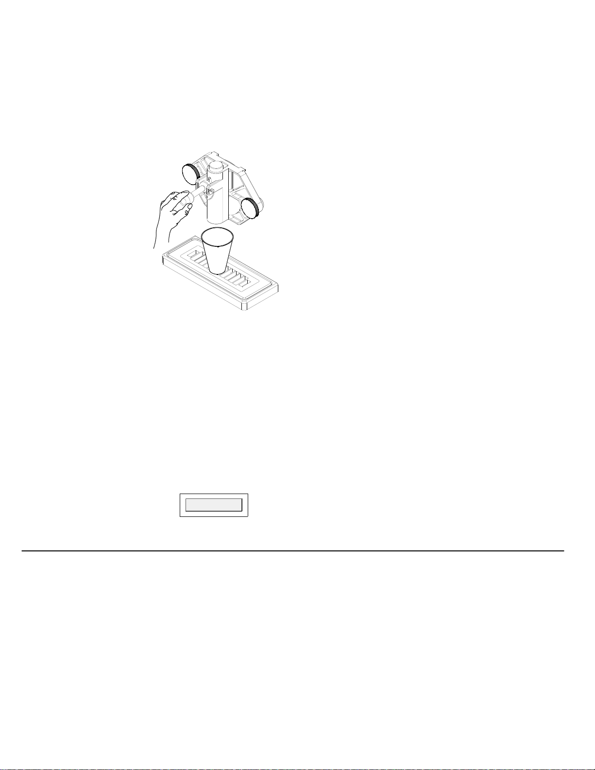
1. Remove the restrictor tube from the bottom of the
mix pan and set aside in a sanitary location.
2. Place a 16 oz. Cup under the spigot and open the
spigot handle. Pour
approximately one quart
of fresh product mix into
the mix pan. (This will
chase the sanitizing
solution from the mix pan
and freezing cylinder.)
Close the spigot handle
when the sanitizer is
purged from the system.
3. Fill the freezing
cylinder until the mix
comes out of the
recirculation hole on
units with two mix inlet
holes or until the freezing
cylinder stops bubbling on units with only one mix inlet
hole.
4. Install the removable restrictor tube with a gentle
twisting motion into the front hole if the mix pan has two
mix inlet holes. For units with only one hole, simply
insert the restrictor tube in the only mix inlet hole.
5. Fill the mix pan with chilled, properly mixed product.
Keep the mix level in the mix pan at least one inch
(25 mm) deep at all times to avoid starving the freezing
cylinder. A MIXOUT light (Fig. 38) located on the front
of the machine (one per freezing cylinder) is activated
when the mix solution drops to a potentially damaging
level.
6. Set the control switch to the “AUTO” position to
start the machine.
7. Allow the compressor to cycle 3 or 4 times
dispensing a sample of the product after each cycle to
check for consistency. If the machine is not dispensing
the product at the desired consistency after four full
cycles, refer to the Consistency Control Section of this
manual. Initial pull-down time may vary due to model,
product and ambient conditions.
8. Replace the mix pan lid and always operate the
machine with the lid on the mix pan reservoir.
Note: SaniServ dispensers are designed to run frozen
beverage products having a Brix (sugar content) range
of 12.5 to 14 with a dispense temperature of 26°F to 28
°F (-3.3°C to -2.2°C).
Brix reading is taken by placing a small sample of
normally diluted concentrate on the viewer of a
refractometer. If a refractometer is not available,
contact the mix supplier.
Do not use a mix with a Brix reading of less than
12.5. Doing so may result in serious damage to the
machine.
If the Brix reading is above 14.0 or the alcohol content
is too high, the freezing point of the solution may be too
low to form slush.
DO NOT ATTEMPT TO MAKE FROZEN BEVERAGE
USING ARTIFICIALLY SWEETENED PRODUCT.
OPERATION
Fig. 37
Dispensing Product
Operation (Filling and Starting)
If the liquid level sensor detects a low level condition, it
will flash the “MIXOUT” light and activate the beeper
for three minutes or until the mix pan is filled to satisfy
the mix level probe. If the beeper is activated for more
than three minutes, the light will begin to glow
continuously, the beeping tone will slow down, and the
machine will no longer dispense product.
Control Switch Positions
“CLEANOUT” Position: The dasher motor operates
continuously and the compressor will not come on.
The mix out level sensor will turn on the “MIXOUT”
light but will not activate the beeper.
“AUTO” Position: The dasher motor operates
continuously. Upon machine start up the compressor
will run until proper product consistency is reached.
Then the compressor will shut off.
MACHINE OPERATIONS WITH ELECTRONIC CONSISTENCY CONTROL
Fig. 38
MIXOUT Light
PAGE 13

Closed Hours/Shut-Down: If the machine is turned
off during closed hours, to resume operation:
1. Set the control switch to the "CLEANOUT" position.
2. Dispense two quarts (2 liters) of product into a
sanitized pitcher and pour it back into the mix pan.
Doing so serves as a mixing process to eliminate any
overnight separation.
NOTE: NEVER POUR FROZEN PRODUCT INTO
THE MIX PAN. LET IT MELT FIRST.
3. Set the control switch to the "AUTO" position and
resume operation.
Mixing: Make certain that the product is prepared per
label instructions. The machine is designed to operate
with frozen product base having a brix range of 12.5 to
14.0. To ensure consistency and quality, use a mixing
container large enough to hold 5 gallons (20 liters) with
1 gallon (4 liter) markings to allow accurate mixing of
the frozen beverage base. Stir well before adding to
the mix solution to the mix pan. Refrigerate the base
after diluting. Keep the empty gallon bottles with their
lids or caps installed and refill them with diluted base
for easy access during busy operating periods.
Filling: Always fill the machine at the start of each
day. Fresh prechilled mix will produce the best results.
Mix Pan Lid: Be sure to leave the lid in place on top of
the machine to prevent any foreign materials from
contaminating the mix.
Drip Tray: This should be removed daily and cleaned
to remove residue (Fig. 37).
Front Plate: This component (Fig. 33) is the plastic
device from which the product is dispensed. It is
designed and made for strength and durability.
However, through improper use, it can be damaged.
Use the following information for proper care.
1. Do not lubricate the large o-ring on the rear of the
front plate. If lubricated, it will not seal properly and
product will leak from the front plate (Fig. 33).
2. Do not over tighten the knobs.
3. Always tighten the front plate knobs evenly. Do
not attempt to turn one knob all the way down and then
the other(s). Doing so will bind the front plate and
result in breakage.
4. Improper installation of the stator rod can cause
breakage. The stator rod must be properly seated in
the dasher before installing the front plate. If the stator
rod is improperly installed, subsequent tightening of the
knobs will break the front plate.
5. Do not attempt to wash the front plate or any other
machine components in a dishwasher.
Mix Out Light: When the mix out light comes on, fill
the mix pan. The mix pan must be filled immediately to
prevent air from entering the freezing cylinder. If air
enters the freezing cylinder, it will create the condition
known as “starving the machine”, causing freeze-up
and vibration. If this condition occurs, set the control
switch to the "OFF" position and add mix to the
mix pan. Allow the freezing cylinder to refill and return
the control switch to the "AUTO" position.
HELPFUL HINTS
Helpful Hints
PAGE 14
This manual suits for next models
4
Table of contents
Popular Beverage Dispenser manuals by other brands


CDS AUTOMATEN
CDS AUTOMATEN ML-16C2-C user manual

Siemens
Siemens GA 3000 OPERATING & SERVICE MANUAL

Bunn
Bunn IMIX Service & repair manual

Fizz Creations
Fizz Creations Slush Puppie Instructions for use

Cornelius
Cornelius IntelliCarb Cold Beverage Dispenser Training manual

TAPRITE
TAPRITE Rattler II Instructional manual