TAPRITE Rattler II Operating and maintenance manual

Please refer to the Taprite website (www.taprite.com) for information
relating to Taprite installation and Service
Manuals, Instruction Sheets, Technical Bulletins, Service Bulletins, etc.
Instructional Manual
Rattler II Beverage Dispenser
Dispenser Model No. 950C
PN: 805-0039C
Rev: F
Released: 9/28/23
NOTICE:
The information contained in this document is subject to change without notice.
TAPRITE MAKES NO WARRANTY OF ANY KIND WITH REGARD TO THIS MATERIAL, INCLUDING, BUT NOT LIMITED TO, THE
IMPLIED WARRANTIES OF MERCHANTABILITY AND FITNESS FOR A PARTICULAR PURPOSE. TAPRITE shall not be liable for
errors contained herein or for incidental consequential damages in connection with the finishings, performance, or
use of this material.
This document contains proprietary information which is protected by copyright. All rights reserved.
© Copyright 2019 by Taprite, all rights reserved.
Taprite
3248 Northwestern Drive • San Antonio, TX 78238
Toll-Free 877.404.2488 •Fax: 210.646.6009 www.taprite.com
3158001
THIS DOCUMENT CONTAINS IMPORTANT INFORMATION
This manual must be read and understood before the installation and operation of this dispenser.

2805-0039C Rev F
TABLE OF CONTENTS
SUBJECT PAGE NUMBER
Installation 3
Setting Ratio 5
Flow Control Cover Installation 7
Butterfly Plate and Button Removal/Reassembly 7
Removing and Replacing Stem O-Ring 8
Cleaning and Maintenance 11
Reattaching the Bar Gun Assembly 13
Troubleshooting 14
Line Configuration 15
Juice and Energy Butterfly Plate Configurations 16
8 and 10 Butterfly Plate Configurations 17
12 and 14 Butterfly Plate Configurations 18-19
Button Plate Configurations 20
Accessories 21-22
Handle Assembly 23-24
Manifold Assembly 25-26
Flow Control Module Assembly 27-28
Mechanical Module Assembly 29-30
Mounting Plate Screw Placement 31
Patent & Patent Pending Numbers 31
Part Number Format 32
APENDIX 33

3805-0039C Rev F
INSTALLATION
Thank you for purchasing a Taprite 950C bar dispenser. All required mounting
hardware, holster assembly, and ¼” stainless-steel input fittings (with o-rings) are
included with each bar dispenser. The stainless-steel input fittings are installed on the
product side of the bar dispenser manifold (Fig. 1). These fittings are secured in place
using the red retainer clips.
Fig. 1
Attach the base plate (smooth side out) with the provided #8 screws. Please see Page 31
for optimal screw placement.
To install the fitting, press the barb side of the fitting into the tubing and past the last
fittings barb. Secure the tubing to the fitting with an Oetiker® clamp positioned upright.
A. If a staggered setup is necessary, input fittings are available in two additional
lengths: “medium” (1.5” length), and “long” (2.7” length) (Fig. 2).
IMPORTANT
THIS EQUIPMENT MUST BE CONNECTED TO A POTABLE WATER SUPPLY AND IN-
STALLED WITH ADEQUATE BACK FLOW PREVENTION TO COMPLY WITH FEDERAL,
STATE, AND LOCAL CODES.
IMPORTANT
THE BASEPLATE PROVIDES STABILITY FOR THE BAR DISPENSER AND SHOULD BE AT-
TACHED TO A FLAT SURFACE. FAILURE TO INSTALL THE BAR DISPENSER AND BASE-
PLATE ON A FLAT SURFACE WILL VOID THE WARRANTY AND MAY CAUSE THE VALVE
MODULE ASSEMBLY TO LEAK.
INSTALLER TIP:
Do not install the tubing flush with the flange, this will cause the tubing to interfere with
the retainer clip. Failure to install Oetikers® as shown in Figure
1
will place stress on the
valve module assembly and cause a leak.

4805-0039 Rev F
Fig. 2
B. Follow the labeling on the assembly to ensure proper product connection.
C. Lock inlet line fittings into the valve module assembly before turning on syrup or
water. To lock the fitting, lightly press down on the red clip. Lightly pull up on the
clip to allow fitting removal. (Caution: Forcibly removing the red clip from the valve
body may damage the clip).
Fig. 3
D. The bar dispenser assembly comes from the factory pre-attached to the valve
module assembly. Before proceeding to the next step verify that the red retainer
clips are in the locked position (down) (Fig. 3).
E. Rotate the yellow shut-off stem 90 degrees to “Off” position to check for
inlet connection leaks (Fig. 4).
Off
Fig. 4

5805-0039 Rev F
F. Slide Flow Control Module/Mechanical Module (FCM/MM) onto base plate and
verify that the two bosses on the plate are lined up. Secure the manifold to the
base plate with the two thumb screws.
G.To install the holster use the screws provided. Install the holster and drain assembly
in close proximity to the bar gun location. Holster mounting plate must be
placed so that the release tab is accessible. Plumb the holster using 1/2”
standard drain hose and follow local plumbing codes. Refer to the cleaning and
maintenance section for proper removal and cleaning of holster.
Release Tab
Fig. 5
SETTING RATIO
The Bar Dispenser has been thoroughly tested and sanitized prior to shipment. The installer
will be required to set the ratio of the bar dispenser.
A. Rotate the yellow shut-off stem to the “on” position (Fig. 4).
B. To adjust water flow rate, press plain water button or carbonated water button on
bar dispenser and capture water in a graduated cylinder or ratio cup, while timing
the dispense. Divide the volume of water dispensed by the time. This will equal the
flow rate in oz/s
C. To adjust the flow, turn the red adjustment screw (Fig 6). To regulate a ceramic
FCM, turn clockwise to increase flow and counterclockwise to decrease flow. If
the flow control assembly contains a green adjustment screw it is a MM. To
regulate flow, turn counterclockwise to increase flow and clockwise to decrease
flow (opposite of ceramic flow control) (Fig. 7)
IMPORTANT
NEVER PLACE THE HOLSTER DIRECTLY OVER THE ICE BIN. HOLSTER INSERT CAN BE
REMOVED AND USED WITH OTHER BAR DISPENSER HOLSTERS.
INSTALLER TIP:
Place your bar dispenser as close as possible to the product cooling source to minimize the
dispensing of warm product and reduce foaming of the finished drinks.
INSTALLER TIP:
Installer must cool or chill the product before setting the ratio of
the system. Ratio will be different in cold product and warm product.
IMPORTANT
BEFORE SETTING RATIO, PURGE PRODUCT AND WATER THROUGH
BAR DISPENSER TO ENSURE PROPER PRODUCT TEMPERATURE.

6805-0039C Rev F
Increase
Decrease
Decrease
Adjustment
Screw Metering
screw
Increase
Fig. 6 Fig. 7
D. To achieve the proper water flow rate, adjust the red screw within the flow
control module. For the mechanical application adjust the green metering
screw (Fig. 7).
E. To Ratio/Brix the final product, remove dispensing nozzle on bar gun assembly.
F. Replace the dispensing nozzle with the Taprite syrup separator nozzle. Line up the
separator nozzle on the diffuser and turn to lock the nozzle in place. Ensure there is a
tight seal against the diffuser.
G. Use a ratio cup to measure the syrup to water ratio. Adjust the flow controls to achieve
the target ratio.
Secondary Water
Ratio Screw
Fig. 8
NOTE:
The Bar Dispenser is designed to flow 1.50 oz/sec. finished drink.
This is the proper setting for 5:1 ratio.
INSTALLER TIP:
Depending on the pressure of the incoming plain water, the maximum flow for the dispens-
er may not be achievable. There are two solutions to this problem.
1)
Adjust the Brix/Ratio to account for the slower flow rate.
2)
Add a water booster to the system.
INSTALLER TIP:
The Taprite Bar Dispenser is equipped with a secondary water ratio screw that is located
on the bottom of the bar dispenser handle near the nozzle (Fig. 8). This may be used to
slow the flow of water to maintain proper ratio for products with ratios
1:1
or 2:1 or any
high-viscosity product. The screw comes from the factory in the open position and should
be used only in the conditions noted. This screw only controls water flow to the products
associated with the bottom right hand butterfly plate.

7805-0039C Rev F
FLOW CONTROL MANIFOLD COVER INSTALLATION
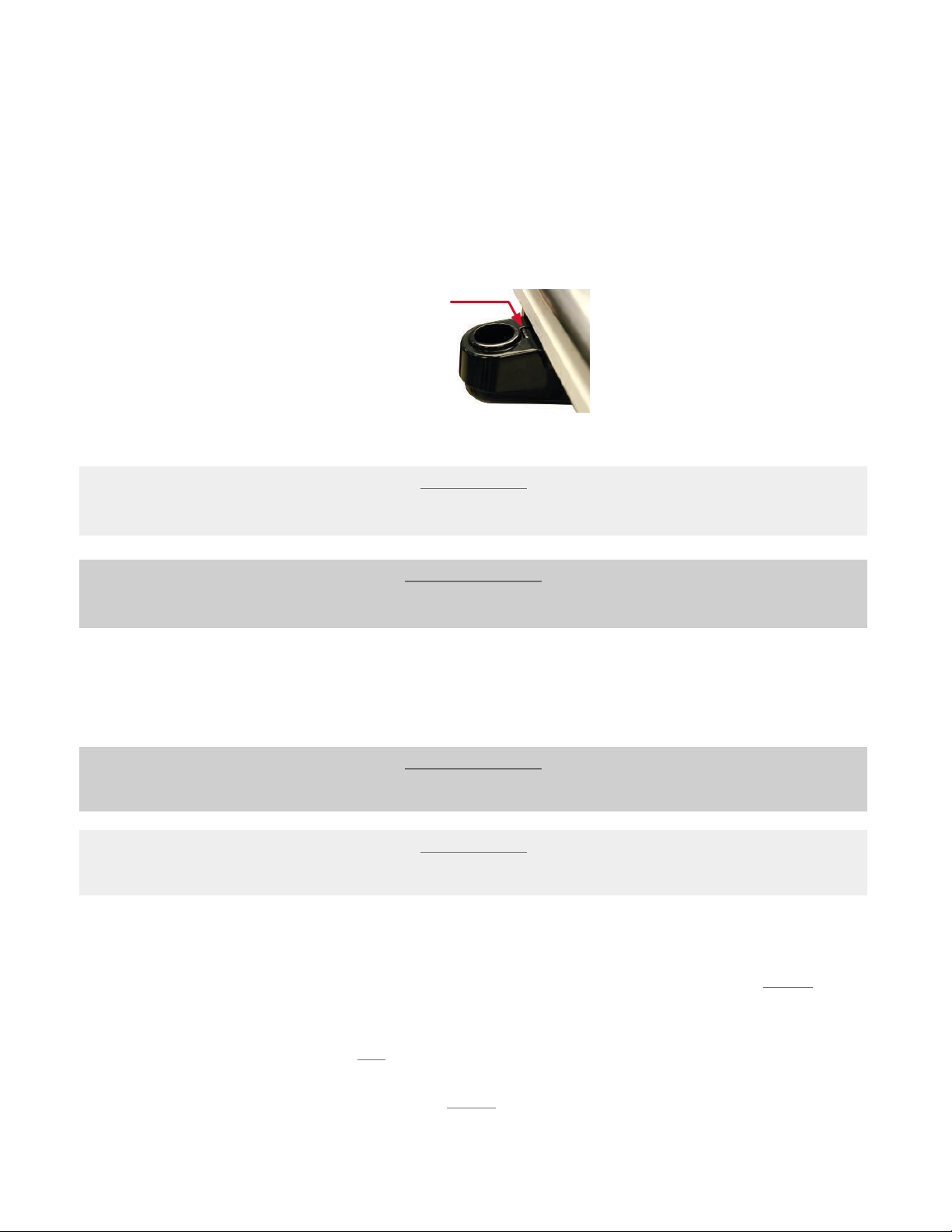
A. Loosen thumb screws, located on the sides, DO NOT COMPLETELY REMOVE
THUMBSCREWS. Lift the cover off the manifold.
B. To install cover, align the slots on the cover with the thumb screws on the valve
manifold assembly.
C. Tighten thumbscrews on each side of cover. DO NOT OVERTIGHTEN.
CAPTIVE O-RING DESIGN (COR)
Below are instructions for the latest revision of the Taprite bar dispenser handle.
The Stem O-rings are located on top of the handle, under the button plate.
The revision includes.
1. Retainers
266-0329 Retainer, O-Ring 5BRC,7BRC,8BRC,10Button
266-0260 Retainer, O-Ring 12Button
266-0361 Retainer, O-Ring 14Button
2. Stem, plunger
265-0865 Stem, Plunger Valve BG Captive
BUTTON AND BUTTERFLY PLATE REMOVAL/RE-ASSEMBLY
The Taprite Bar Dispenser handle can be configured into numerous combinations of
carbonated and non-carbonated products. All combinations can be made without
shutting down the system.
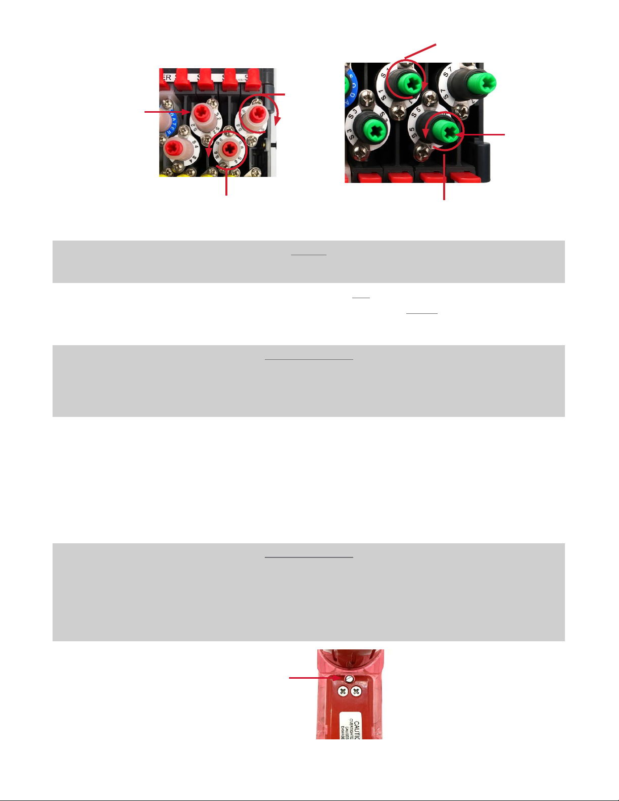
Begin by removing the (2) 6-32x0.5” button plate screws located on top of the handle, do
not discard, see Fig. 9 below.
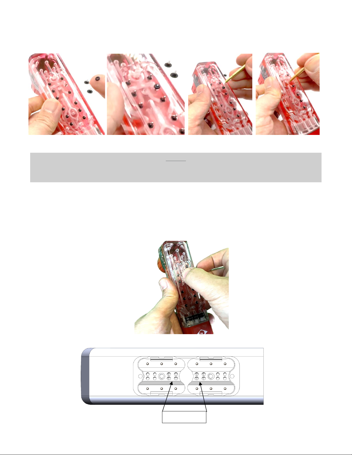
A. To change the butterfly plate(s). Remove the (2) 6-32x.0375” screws and (2) butterfly
(black)retainers, Fig.10.
B. Remove butterfly plates from handle Fig. 11, save screws and butterfly retainers for re-installing.
C. Ensure that the o-ring retainer(s), Fig. 12, below the butterfly plates, are correctly in place before
replacing butterfly plates as required.
D. Align the pivot balls, at the bottom of the butterfly plates, with the divots in the o-
ring retainer.
E. Secure butterfly plate(s). Use the (2) 6-32x.0375” screws and (2) butterfly
(black)retainers. DO NOT OVERTIGHTEN.
F. Replace button plate and re-attach with the (2) 6-32x0.5”.
INSTALLER TIP:
Verify the O-Rings are seated properly and add lubricant before re-installing
components, see instructions on Removing and Replacing Stem O-Ring.
NOTE:
SEE “Non-Captive Stem O-Ring Service”IN THE APPENDIX for instructions on removing
and replacing stem o-rings from the bottom of the handle.

8805-0039C Rev F
REMOVING AND REPLACING STEM O-RING
The Stem O-rings are located on top of the handle, under the button plate.
Begin by shutting off pressure. Rotate the (yellow) shut-off stem(s) 90 degrees counterclockwise
on the valve manifold, Fig.4.
A. Press the buttons on the handle to release any pressure.
B. Remove the button and the butterfly plates, see instructions Button and Butterfly Plate
Removal/Re-Assembly.
Fig. 9 Fig. 10 Fig.11
Fig.12
NOTE:
The new retainer design allows one to service and replace the stem O-rings
without the need to remove the bottom plate.
266-0361
14B Handles
266-0360
12B Handles
266-0329 (x2)
7,8,10B Handles
266-0329
5B Handles

9805-0039C Rev F
C. Remove O-Ring retainer by tilting the handle upside down, Fig.13. If retainer(s)
does not fall out, carefully lift the clear retainer straight up by lightly applying
outwards pressure with your fingers on the tabs of the retainer, see Fig. 14, and
slowly guide up through the plunger stem(s). Inspect retainer for wear or cracks
replace if damaged.
Fig.13
Fig.14
D. Using the O-ring tool, PN 316-0028, carefully remove the O-ring(s) that need to be replaced,
Fig. 15. Be careful not to damage the O-ring gland as this may lead to leaks.
Fig. 15
NOTE:
During removal, retainer(s) should have little to no resistance when guided evenly off the
surface of the handle. The plunger stems will restrict the movement of the retainer if angled
too much.

10 805-0039C Rev F
E. Insert the lubricated replacement O-ring, PN 208-5003, over the plunger stem and install into
the bottom of the gland using the PN 316-0028 O-ring insert tool, Fig. 16.
Fig. 16
F. Replace the retainer(s) by aligning the holes over the stem plunger and slide down onto
the handle, see Fig. 17.
The oval divots in PN 266-0329 are designed to face towards the center of the handle, see
Fig. 18. However, orientation of the retainers is only critical on 14B handles (266-0361
retainer), which is why there is an up arrow indicating the proper orientation, see Fig. 12.
Fig. 17
Fig. 18
NOTE:
Failure to shut off flow to the handle may result in a high-pressure blast of water or
syrup to be shot out of the o-ring gland if plunger stem is accidentally depressed.
Oval divots

11 805-0039C Rev F
Do not over tighten
G. Assemble the butterfly plates and retainer, fasten to 2.5 inlb max.
H. Replace button plate, see Fig 9.
CLEANING AND MAINTENANCE
The Bar Dispenser is shipped from the factory cleaned and sanitized in accordance with NSF
guidelines. The bar dispenser must also be cleaned and sanitized after installation is
complete. It is recommended that the operator provide continuous maintenance as
required by the manual and/or state and local guidelines to ensure proper operation.
A.
External Cleaning
Cleaners (ivory liquid, calgon, etc.) should be mixed with clean potable water at a
temperature of 90 to 110 degrees F. The acceptable mixture ratio is one ounce of
cleanser to two gallons of water. Any NSF approved equivalent cleaner may be
used. Rinse with clean potable water.
B.
Sanitizing
Sanitizing solutions must provide 50 to 100 parts per million (PPM) available chlorine.
Any sanitizing solution may be used as long as it is prepared in accordance with the
manufacturer’s recommendations.
IMPORTANT:
Exceeding the max torque on the butterfly screws may impede proper function of
the butterfly plate(s) and can strip threads on the handle.
IMPORTANT
DO NOT CLEAN WITH OR ALLOW CONTACT WITH HARSH CHEMICALS CONTAIN- ING
ATBC (ACETYL TRIBUTYL CITRATE) OR OTHER ORGANIC SOLVENTS (CLEANER/
DEGREASERS, PESTICIDES AND PESTICIDE FOGGERS). THIS WILL CAUSE PERMANENT
DAMAGE TO PLASTIC COMPONENTS.
DO NOT SUBMERGE THE HANDLE IN HOT WATER. THIS WILL CAUSE PERMANENT
DAMAGE TO THE DISPENSER AND ITS COMPONENTS.
IMPORTANT
ONLY USE INTERNAL CLEANING SOLUTIONS THAT ARE APPROVED FOR BEVERAGE
DISPENSER APPLICATIONS, SUCH AS KAY-5®. (NO CAUSTIC CHEMICALS SUCH AS
INDUSTRIAL KITCHEN CLEANING CHEMICALS SHOULD EVER BE USED)

12 805-0039C Rev F
C.
Daily Cleaning
1.
Dispenser Handle
a. Prepare sanitizing solution.
b. Remove nozzle by twisting counterclockwise and pulling down and submerging nozzle
into a sanitizing solution for 15 minutes. The diffuser is not removable.
c. Wash diffuser and sanitize:
i. Use Nozzle Sanitizing Assy. (PN 631-0187) accessory: Fill nozzle with
sanitizing solution and install onto diffuser by twisting clockwise while
pushing up onto diffuser. Leave on for 15 minutes.
ii. Or, if Sanitizing Nozzle Assy. is not utilized, wash diffuser, rinse and
immerse the diffuser only in sanitizing solution for 15 minutes.
d. Remove diffuser and nozzle from sanitizing solution, air dry. Reinstall nozzle on diffuser.
D.
Deep Cleaning of Bar Dispenser Whip
1.
Rotate yellow Shut-off stem 90 degrees to turn off water/product (Fig. 19).
2.
Turn the two (2) wing screws to release the FCM/MM from the base plate (Fig 20).
3.
Slide FCM/MM module out of mounting plate.
4.
Snap the red retainer clips to the open position (Fig 21).
5.
Locate the two slotted red screw separators on the outside of the bar gun manifold and
turn the screws clockwise. This will separate the bar gun dispenser from the FCM/MM
module (Fig. 22)
Fig.19 Fig.20
Red Clips Fig. 21 Fig. 22
NOTE:
Alternate turning red screw separator to evenly remove the bar gun manifold from
the module. The Shut-off tool (P.N. 316-0005), or a screw driver, can be used to aid in
removing the dispenser assembly but is not necessary.
NOTE:
DO NOT submerge handle assembly into sanitizing solution!!
NOTE:
Diffuser is NOT removable, attempting to remove diffuser may damage dispenser

13 805-0039C Rev F
6.
Fill a bar sink or a 5 gal. bucket with sanitizing solution that is mixed to mfg.
recommendations (50 to 100 PPM). Allow the bar gun whip assembly to soak
in the solution for 10 to 15 minutes. Using a cloth and brush, wash and clean the
hose. Inspect the hose to ensure all residue is removed. It should not be soaked
overnight.
7.
Rinse with warm water and allow to dry.
E.
Holster Cleaning
1.
Daily Cleaning
For daily cleaning, press carbonated water button or water button on bar handle
while sitting in the holster to flush product residue down drain. You may also pour
warm water down the receptacle to clean holster.
2.
Bi-weekly Cleaning
a.
To remove holster assembly, push tab located behind the nozzle receptacle.
Slide holster assembly forward (toward you) (Fig. 23-24).
b.
Separate the bar gun receptacle from the drip tray (Fig. 25).
c.
Refer to sanitizing section in 3-B.
Fig. 23 Fig. 24 Fig. 25
REATTACHING THE BAR GUN WHIP ASSEMBLY
A. Adjust the red screw separators on the outside of the bar gun assembly so the
small smooth shank is exposed.
B. Slide the bar gun manifold into the FCM/MM module.
C. Snap red retainers into the locked position.
D. Slide FCM/MM module and bar dispenser into locked position on mounting plate
and secure with wing screws
E. Rotate yellow Shut-off stem 90 degrees to the open position and check for leaks.
F. Depress all buttons on bar dispenser head to remove any trapped air or sanitizing solution.
G. Bar Dispenser is ready for operation.
NOTE:
Check the back of the drip tray drain connector to ensure there is no damage to the
o-rings
(P.N. 208-5112-429) (Fig. 25)

14 805-0039C Rev F
TROUBLE SHOOTING
A. Push water - no water dispensed
•
Check water supply
•
Check Shut-off (is it open)
•
Check ratio/brix adjustment
•
Check for proper butterfly plate
B. Push syrup - no syrup dispensed
•
Check C02pressure
•
Check for product
•
Check Shut-off
•
Check ratio/brix adjustment
•
Line plugged
C. Push soda - no soda dispensed
•
Check carbonator
•
Check water supply
•
Check C02pressure
•
Check Shut-off
•
Check ratio/brix adjustment
•
Check for proper butterfly plate
D. Push product - dispensing incorrect product
•
Check for proper plumbing
•
Check for proper butterfly plate
E. Weak product taste
•
Check syrup C02supply
•
Check ratio/brix adjustment
•
Check for plugged line
•
Check Shut-off - open completely
•
Check syrup supply
F. Strong product taste
•
Check ratio/brix adjustment
•
Check carbonator pressure
•
Check syrup C02
G. Continuous dispense
•
Check butterfly plates - damaged or too tight
•
Check for debris in syrup or water passages
H. Product leaking from bottom plate
•
Defective stem o-ring
•
Bottom plate screws are loose
•
Warped or damaged button plate

15 805-0039C Rev F
LINE CONFIGURATION
8 Button 10 Button
12 Button 14 Button
S5
S6
S1 S3 S4 S2
END OF HANDLE
S5
S6
S1 S3 S4 S2
S7
S8
END OF HANDLE
S1 S2
SODA
S3 S4
S5 S6
WATER
S1 S2
SODA
S3 S4
S5 S6
WATER
S7 S8
S7 S5 S1 S3
SODAWATER S4 S2 S6 S8
S7 S5 S1 S3
SODAWATER S4 S2 S6 S8
UP
WATER
END OF HANDLE
UP
808-0071
S7
S9
S5 S6
SODA
S8
S1 S3 S4 S2
S11 WATER S12
END OF HANDLE
808-0063
SODA
WATER
S1 S2
S3 S4
S5
S7
S9
S6
S8
S10
S11 S12
INLET SIDE
S11 S9 S7 S5 S1 S3
SODA WATER S4 S2 S6 808-0062 S8 S10 S12

16 805-0039C Rev F
JUICE AND ENERGY BUTTERFLY PLATE CONFIGURATION
= Carbonated Positions
= Non-Carbonated
Positions
= Secondary Water Metering Screw Affects These Positions
® = Requires Soda/Water Button Foot (P.N. 265-0039/265-0040)
Extensions Into Bottom Of Button Where Symbol Appears.

17 805-0039C Rev F
8 AND 10 BUTTON BUTTERFLY PLATE CONFIGURATIONS

18 805-0039C Rev F
12 AND 14 BUTTON BUTTERFLY PLATE CONFIGURATIONS

19 805-0039C Rev F
12 AND 14 BUTTON BUTTERFLY PLATE
CONFIGURATIONS

20 805-0039C Rev F
BUTTON PLATE CONFIGURATIONS
007
659-0007
8 BUTTON
6C/0NC
001
659-0001
10 BUTTON
5C/3NC, 6C/2NC,
8C/0NC
003
659-0003
12 BUTTON
6C/4NC,
7C/3NC
005
659-0005
14 BUTTON
6C/6NC,
8C/4NC
PLEASE CONTACT CUSTOMER SERVICE FOR OTHER PLATE CONFIGURATIONS
This manual suits for next models
2
Table of contents
Popular Beverage Dispenser manuals by other brands

Cornelius
Cornelius 15 Gallon Single-Flavor Visual Display Dispenser... Training manual

Cornelius
Cornelius Tea Tower Specification sheet

Newco
Newco LCD-1 Installation and programming guide

Hoshizaki
Hoshizaki DM-180A6 parts list

Ugolini
Ugolini INSTANT 20/2 Operator's manual

Gastrorag
Gastrorag DK50 instruction manual