AFX Fireblocker Carbon Series User manual

1
User Manual AF-X Firestopper November 2015 version 1
Installation and User Manual
AF-X Fireblocker Carbon Series
Original issue date: July 2018
Revision date: 07-12-2019
Version: 2.3

Please keep this user manual for future use. It will expire upon
publication of a revised issue. The latest version is available with your
distributor, dealer or at AF-X Systems BV.
User Manual AF-X Fireblocker Carbon Based Fire Extinguishers version 2.2
2
Installation and User Manual AF-X Fireblocker Carbon Series
Original issue date : July 2018
Revision date : 07-02-2019
Version : 2.2
Author : AF-X Systems BV
Published by : AF-X Systems BV
Grasweg 49
1031 HX Amsterdam
The Netherlands
Telephone : +31 (0)20 – 20 50 484
H-page : www.af-x.com
E-mail : info@af-x.com
Lay-out : In accordance with NEN-5509
This manual is the manufacturer’s design, installation, operating and maintenance instruction manual for detailed
instructions for correct usage and maintenance.
Please read this user manual carefully before installing
AF-X Fireblocker Carbon Based Fire Extinguishers.
AF-X Systems BV general terms and conditions can be retrieved at the Chamber of Commerce, Amsterdam office.
Copyright©
All rights reserved. Nothing in this publication may be reproduced and/or made public by means of printing,
photocopying, microfilm or any other method without prior written consent from AF-X Systems BV.
It is permitted to offer this manual to stakeholders for inspection.
ã2018 AF-X Systems B.V.

Please keep this user manual for future use. It will expire upon
publication of a revised issue. The latest version is available with your
distributor, dealer or at AF-X Systems BV.
User Manual AF-X Fireblocker Carbon Based Fire Extinguishers version 2.2
3
Content
1.0 Introduction .......................................................................................................................................... 6
2.0 Scope ..................................................................................................................................................... 6
3.0 Design of the AF-X Fireblocker Carbon Series .................................................................................. 7
4.0 Precautions and safety instructions ................................................................................................... 8
5.0 Design and installation of the fire extinguishing system ................................................................. 9
5.1 The Fire extinguishing control panel (FECP) ............................................................ 9
5.2 AF-X MCU (monitoring & control unit) ...................................................................10
5.3 Detection systems and peripheral equipment.........................................................11
5.4 AF-X Fireblocker Carbon Series extinguishing generators.........................................11
5.5 AF-X Fireblocker Carbon Series aerosol behaviour ..................................................11
5.6 Calculation of quantity and type...........................................................................11
5.7 Projection of the generators within the area ..........................................................11
5.8 Guidelines for the correct positioning and distribution in the area .............................11
5.9 Determination of the correct discharge direction ....................................................12
5.10 Mounting guidelines AF-X Fireblocker Carbon generators .........................................14
6.0 Product Label ........................................................................................................................................... 16
7.0 Storage and transport ........................................................................................................................ 16
8.0 Maintenance of the AF-X Fireblocker ................................................................................................ 17
9.0 Residue removal, disassembly, waste and the environment .......................................................... 17
9.1 Introduction ......................................................................................................17
9.2 Residue removal ............................................................................................................................................ 17
9.3 Disassembly after the AF-X Fireblocker has been activated ........................................................ 18
9.4 Disassembly of an AF-X Fireblocker unit. ............................................................................................ 18
9.5 Waste and the environment ..................................................................................................................... 18
10.0 CE-Marking .......................................................................................................................................... 18
Annex 1 General Technical Data ................................................................................................................... 19
Annex 2 General technical data Bimetal Switch .......................................................................................... 20
Annex 3 Safety Data Sheet ........................................................................................................................... 20

Please keep this user manual for future use. It will expire upon
publication of a revised issue. The latest version is available with your
distributor, dealer or at AF-X Systems BV.
User Manual AF-X Fireblocker Carbon Based Fire Extinguishers version 2.2
4
Signs to indicate prohibitions, mandatory actions and cautions used in this manual
PROHIBITION
MANDATORY
ACTION
Beware
No switching off
No switching on
Foot
protection
MANDATORY
ACTION
Attention /
important
Eye protection
Head
protection
Hand
protection
Unplug /
disconnect
CAUTION
Fragile
Fall danger
Hot surface
Damage

Please keep this user manual for future use. It will expire upon
publication of a revised issue. The latest version is available with your
distributor, dealer or at AF-X Systems BV.
User Manual AF-X Fireblocker Carbon Based Fire Extinguishers version 2.2
5
Foreword
Trademarks
AF-X®, AF-X Fireblocker®and AF-X Systems®are registered trade, word and figurative marks.
Patents
AF-X Systems BV has several registered patents, including the patent for ‘Fire Extinguishing Composition’ under
number PCT/NL2012/050079.
Information on regulations
The following international norms are valid for our products: CEN/TR 15276-1/2, NEN-ISO 15779 and NFPA 2010.
In addition to these norms various authorities issue directives or standards regarding the use and installation of
aerosol fire extinguishing systems. Examples are the UL 2775 and GOST R 51047-97. There are also local directives,
norms or regulations.
When this document went to print, the editions mentioned were in force. All norms can be subject to revision
however; parties entering into agreements based on this document are therefore recommended to ascertain that
they are using these norms’ latest versions.
The AF-X Fireblocker Carbon Series has been designed, developed and built in accordance with the guidelines of the
following norms/standards.
• ISO norm : NEN-ISO 15779
• European norm : EN 15276
• US norm : NFPA 2010
• Maritime norm : MCD.1/Circ. 1270 (IMO)
• US standard : UL 2775
• Russian standard : GOST R 51047-97
All tests performed on the AF-X Fireblocker Carbon Series have been done according to the norms of the EN 15276
and NEN-ISO 15779. This present manual is based on the results that comply with the EN15276, NEN-ISO15779
and UL2775. The AF-X Fireblocker Carbon Series are delivered under CE Marking. A generator must be installed,
inspected and maintained by qualified personnel with a minimum age of 18 years in compliance with local laws and
regulations for installation and use of aerosol units and fire extinguishing systems.

Please keep this user manual for future use. It will expire upon
publication of a revised issue. The latest version is available with your
distributor, dealer or at AF-X Systems BV.
User Manual AF-X Fireblocker Carbon Based Fire Extinguishers version 2.2
6
1.0 Introduction
The AF-X Fireblocker Carbon Series is designed to extinguish a fire. The authors of this user manual have constructed
it in such a way that it covers every important aspect of the AF-X Fireblocker Carbon Series’ functional use. To
ensure functional use of the AF-X Fireblocker Carbon Series, all instructions of this manual need to be followed
closely.
Electrical installations, such as fire detection, control and alarm systems, need to be installed by the relevant
system’s supplier’s specially trained (certified) personnel according to the system’s suppliers manual and
instructions. These matters are therefore not included in this user manual.
In case of incorrect use of this manual neither AF-X Systems BV, nor the AF-X Fireblocker Carbon Series distributor
or dealer can assume any responsibility.
2.0 Scope
AF-X Fireblocker Carbon Series is based on a condensed aerosol and designed to be part of a fire extinguishing
system. Precondition for powerful performance is the unit’s connection to and activation by an effective fire detection
system. Rapid detection and reaction are vital.
AF-X Fireblocker Carbon Series can be used in ambients which are:
- Normally non-occupied
- conditions that are static
AF-X Fireblocker Carbon Series cannot be used with:
- Materials with deep-seated fire potential, i.e possible chain reaction of the organic fuel, oxygen and
temperature within the material(s), without drawing any of these elements from the outside, e.g. in cocoa
beans, rubber.
- Oxygenic chemical compounds such as nitrocellulose and gunpowder;
- Reactive metals such as lithium, sodium, potassium, magnesium, titanium, zirconium, uranium and
plutonium;
- Metal oxides;
- Organic peroxides and hydrazine

Please keep this user manual for future use. It will expire upon
publication of a revised issue. The latest version is available with your
distributor, dealer or at AF-X Systems BV.
User Manual AF-X Fireblocker Carbon Based Fire Extinguishers version 2.2
7
3.0 Design of the AF-X Fireblocker Carbon Series
General description:
1) The AF-X Fireblocker Carbon Series generator has a steel casing and comes in various shapes and sizes see
annex 1.
2) The AF-X Fireblocker Carbon Series generators contain a solid, aerosol-forming compound (“SAFCO”).
3) Each container is equipped with a special system for independent activation of the generator.
4) All types are equipped with a heat absorbing mechanism (insulation).
A tension of 12/24 V (Direct Current) on the AF-X Fireblocker Carbon Series generator and an electric current of at
least 0,02 amperes for 1,0 seconds activates the extinguishing agent and convert it into dispersed micro and nano
particles. The aerosol is then cooled by the heat absorbing elements and discharged into the protected area, blocking
the fire by stopping the combustion chain reaction. Activation simultaneously triggers other chemical reactions
ensuring a final product that is harmless to man, matter and the environment.
All generators of the Carbon Series are equipped with:
• An integrated AF-X connector for swift and flawless installation
• An activator for electronic activation
• A transportation bracket to neutralize outflow pressure
Schematic illustration of the cylindrical AF-X Fireblocker Carbon Series generator:
1) Reinforcement backplates for safe operation
2) Insulated sides and backside
3) Centralization and stabilization device
4) Tablets of carbon-based aerosol forming compound
5) Separation rings for an open structure to ensure maximum conversion
6) Thermodynamic cooling to ensure a controlled efflux temperature
7) Open nozzle for optimal mixture with air in the protected space
2
3
6
7
5
1
4

Please keep this user manual for future use. It will expire upon
publication of a revised issue. The latest version is available with your
distributor, dealer or at AF-X Systems BV.
User Manual AF-X Fireblocker Carbon Based Fire Extinguishers version 2.2
8
Schematic illustration of the Box shape AF-X Fireblocker Carbon Series generator:
1) Reinforcement backplates for safe operation
2) Insulated sides and backside
3) Centralization and stabilization device
4) Tablets of carbon-based aerosol forming compound
5) Separation rings for an open structure to ensure maximum conversion
6) Thermodynamic cooling to ensure a controlled efflux temperature
7) Open nozzle for optimal mixture with air in the protected space
4.0 Precautions and safety instructions
Read this user manual carefully before putting the AF-X Fireblocker Carbon Series into use.
This user manual contains precaution and safety instructions to ensure a safe execution of the necessary steps.
The term ‘steps’ may refer to all actions in the various product phases: transport, receipt, storage, assembly,
connection of the product, mounting and/or installation, treatment and/or use, maintenance, visual inspection,
repairs, decommissioning, disassembly, removal, disposal, waste, health, safety and the environment.
Warning: the AF-X Fireblocker Carbon Series may only be installed, maintained or serviced by technically qualified
and trained persons and in accordance with the latest applicable local laws, regulations and norms.
2
3
6
7
5
1
4

Please keep this user manual for future use. It will expire upon
publication of a revised issue. The latest version is available with your
distributor, dealer or at AF-X Systems BV.
User Manual AF-X Fireblocker Carbon Based Fire Extinguishers version 2.2
9
When working with the AF-X Fireblocker Carbon Series it is prohibited to:
- open and/or dismantle extinguishing units;
- by any means apply force to the units that could result in distortion, physical or mechanical
damage to the casing;
- carry out welding activities in the vicinity of the AF-X Fireblocker extinguishing units;
- smoke in the vicinity of the AF-X Fireblocker extinguishing units.
In case an extinguishing unit has fallen, it should be checked for damage to the activator’s electric
switch and/or other components. When damage and/or dysfunction cannot be ruled out with
certainty, the unit cannot be used and must be returned to the authorised AF-X distributor or
dealer.
Please see to it that all legal requirements, regulations and advice are adhered to. Pay attention to the
risks involved in working at height. Be careful of your footing and use reliable tools and proper personal
protective equipment. Should you have any queries, please consult your employer and/or qualified
consultancy agencies.
To avoid unnecessary exposure of occupants to the discharged extinguishant, factors such as the time
for egress and the risk to the occupants by the fire should be considered when determining the system
discharge time delay. Where national standards require other precautions, these should be
implemented
5.0 Design and installation of the fire extinguishing system
A standalone AF-X Fireblocker Carbon Series generator can be activated by means of a thermal circuit (e.g. an AF-
X bimetal switch that activates at 65 ºC, see annex 2).
The self-activation temperature of the compound is 350 ºC. The self-activation time of the electronically controlled
activation device is > 170 ºC. Please note that equipment used for heating or welding, and other sources of energy,
might provoke activation of the fire extinguishing generator if the self-activation temperature is reached.
The standard requirements for an aerosol fire extinguishing system with extinguishing generators are:
1. The Fire Extinguishing Control Panel FECP (whether or not connected to a Fire Alarm System, FAS) which
connects, supplies power to, monitors and controls the various components of the extinguishing system.
2. Detection equipment feeding the FECP with information on possible fire hazards.
3. Alarm system giving acoustic or optical signals to warn or inform people present in the protected area about
the current situation.
4. AF-X Fireblocker Carbon Series extinguishing units (generators) that, when activated by the FECP, discharge
the fire blocking aerosol into the protected area.
5. Wiring and connectors connecting the various parts of the system. Often included in this group are alarm
enabling and disabling switches for manual intervention in the FECP controlled process.
5.1 The Fire extinguishing control panel (FECP)
There are many fire extinguishing systems on the market. When selecting your FECP it is important to consider the
local rules and regulation concerning fire extinguishing systems in general and aerosol fire extinguishing systems in
particular.
The extinguishing generators and other equipment must be fed with the required activation voltage and current.
Note that the extinguishing generators are activated by a heating element with 6,8 (±10%) Ohm resistance. The
required electric activation voltage is 12/24 Volt DC with 1,2 Ampère for not less than 1 seconds. A control or test
current of no more than 0,02 Ampère can be applied without activating the generator.

Please keep this user manual for future use. It will expire upon
publication of a revised issue. The latest version is available with your
distributor, dealer or at AF-X Systems BV.
User Manual AF-X Fireblocker Carbon Based Fire Extinguishers version 2.2
10
(European) Extinguishing systems with the AF-X Fireblocker Carbon Series can be designed using one of the
following control panels:
1. Kentec Sigma XT or A-XT panel
2. Honeywell Notifier RP1r-SURPA
3. Siemens Cerberus, for systems with more than 10 extinguishing generators
4. AF-X Marine Panel for shipping
5. DECU2
6. AF-X TEC
All these control panels have their own prices and possibilities. If the usage of other brands or types of control
panels is considered it is required to contact the technical department of AF-X Systems first for an opinion and
approval regarding compatibility. Also, if a certifying authority requires the usage of a specific panel.
For proper installation of the panel of your choice, we expressly refer you to the manufacturer’s installation
requirements.
For installations designed for countries where European Rules & Regulations do not apply, we advise to consult the
technical department of AF-X Systems first for proper advice regarding this matter.
5.2 AF-X MCU (monitoring & control unit)
The AF-X MCU provides connection from the Kentec XT, AX-T or the Honeywell Notifier RP1r-SURPA fire control
panel to the AF-X Fireblocker Carbon Series generators.
• A maximum of 18 AF-X MCU’s can be connected to each extinguishing line,
• A maximum of 2 generators on each MCU.
Connection diagram Notifier RP1r-SURPA:
Connection diagram Kentec Sigma XT or A-XT panel:

Please keep this user manual for future use. It will expire upon
publication of a revised issue. The latest version is available with your
distributor, dealer or at AF-X Systems BV.
User Manual AF-X Fireblocker Carbon Based Fire Extinguishers version 2.2
11
5.3 Detection systems and peripheral equipment
The fire extinguishing system’s Statement of Requirements determines which detection system and/or peripheral
equipment will be chosen. For European extinguishing systems, AF-X Systems uses equipment such as (optical)
alarms, temperature-sensitive equipment or aspiration systems for detection. In addition, systems and switches
might be used enabling manual intervention in the FECP-controlled process.
The AF-X Systems price list includes most of such products enabling the system designer to use standardized and
compatible products.
Please be aware that local rules and regulations, or a certifying authority, may require specific equipment. For
proper installation of the systems, the manufacturers’ installation requirements are leading.
5.4 AF-X Fireblocker Carbon Series extinguishing generators
For the correct design of an AF-X Fireblocker system, the following steps must be taken:
1. Calculation of the required quantity and type of extinguishing generators.
2. Projection of the generators’ correct position in the (to be) protected space.
3. Determination of the extinguishing generators’ correct discharge direction.
5.5 AF-X Fireblocker Carbon Series aerosol behaviour
For a correct design of an AF-X Fireblocker extinguishing system with the Carbon Series, one should consider several
properties and behavioural aspects of the AF-X Fireblocker aerosol of the Carbon Series in the protected space.
The aerosol formed by the AF-X Fireblocker leaves the generator at some speed. You will observe a spreading,
homogeneous cloud. The temperature of this cloud, consisting of extremely small microscopic particles, is usually
higher than its surroundings. Therefore, the aerosol cloud will initially seem to be slowly rising.
The particles are so small that gravity hardly affects them, and they can therefore disperse in the air rapidly and in
a balanced fashion. This also means that the currents and whirls present in the area (either caused by fire, or just
by the active equipment) make the tiny aerosol particles actively move through the protected space. The AF-X
Fireblocker aerosol of the Carbon Series has been designed to make use of these currents and movements so that
the convection currents, caused by the seat of the fire, draw the particles into that seat. Even when the fire is just
in its early stages of development.
5.6 Calculation of quantity and type
The calculation of the necessary quantity and type of extinguishing generators is simple and in principle all you need
is the net volume (in m3) of the space you want to protect. The net volume is usually specified on the Program of
Demand of the project, or at Technical Drawings of the construction. Should you lack this information, you will find
more information in the “Manual Volume Calculation” that is available on request. If the net volume of the to be
protected space is provided to the system designer by a third party, it is strongly advised to check this number
based on factual information.
When you have the available net volume of the to be protected space at hand you can use the “AF-X Fireblocker
Density Calculation Sheet” to determine the amount of extinguishant you need, and which types of extinguishing
generators will best suit your purpose. This Calculation Sheet is available upon request with AF-X Systems at all
times.
For each generator type, the volume the generator protects is stated by fire class. In line with most European and
American guidelines, one should add an (extra) safety margin of 30% in the calculation (this margin is included in
the numbers in the Calculation Sheet).
5.7 Projection of the generators within the area
There is a number of guidelines that help you determine the best positions for the generators in your design. These
guidelines are based on standards, but each area is different. It is important to adhere to the standards as much as
possible. Needless to say, the distribution of generators in the area needs to be in accordance with local rules and
regulations as well as the system’s Statement of Requirements.
5.8 Guidelines for the correct positioning and distribution in the area
1. Generators need to be positioned and distributed in such a way that the discharged aerosol can be dispersed
in the protected area’s free space as quickly and homogenously as possible.

Please keep this user manual for future use. It will expire upon
publication of a revised issue. The latest version is available with your
distributor, dealer or at AF-X Systems BV.
User Manual AF-X Fireblocker Carbon Based Fire Extinguishers version 2.2
12
2. Generators are preferably mounted on the wall or at the ceiling, with the discharge opening pointing
downwards at an angle from the ceiling or wall respectively (cf. ‘discharge direction’ below). The higher
and or bigger the enclosed space, the more vertically downwards the generator should be directed. If a
space is protected by one generator only, it might be best to mount the generator pointing downwards in
the centre of the ceiling.
3. The units need to be evenly distributed in the area.
One larger generator could be more cost effective than two smaller, the use of two generators could be
more effective than using four, but there are no absolutes. The deciding factor on the number of generators
in the design should be based on whether the chosen number could fill the area with aerosol rapidly and
evenly. After all, every nook and cranny need to be filled with sufficient aerosol. When in doubt, do not
hesitate to contact the AF-X Systems experts.
5.9 Determination of the correct discharge direction
There are always several solutions. The challenge is to come up with the optimal mix of choices in type, position
and discharge direction and length that makes maximum use of AF-X Fireblocker’s qualities and is in accordance
with the Statement of Requirements as well as the local rules and regulations.
4. Preferably, generators are mounted to the wall just under the ceiling with the discharge opening directed
downwards.
If a free downward outflow is not possible, the generators can be mounted on the ceiling, also with the
discharge opening directed downwards.
5. Generators need to be positioned in such a way that all discharged aerosol is dispersed unhampered and
in full in the area to be protected. This also implies that the generators always need to be projected
towards unobstructed space, away from windows, doors, grates, vents, lids, valves, man-holes, transom
windows or other openings. This includes openings that are usually closed or pushed closed with door-
closers or automatically by the FECP before extinguishing starts.
Away from doors:

Please keep this user manual for future use. It will expire upon
publication of a revised issue. The latest version is available with your
distributor, dealer or at AF-X Systems BV.
User Manual AF-X Fireblocker Carbon Based Fire Extinguishers version 2.2
13
Away from windows or other potential openings:
6. In an area with a height of less than 1m, generators should preferably discharge horizontally.
Horizontal discharge in areas lower than 1m:
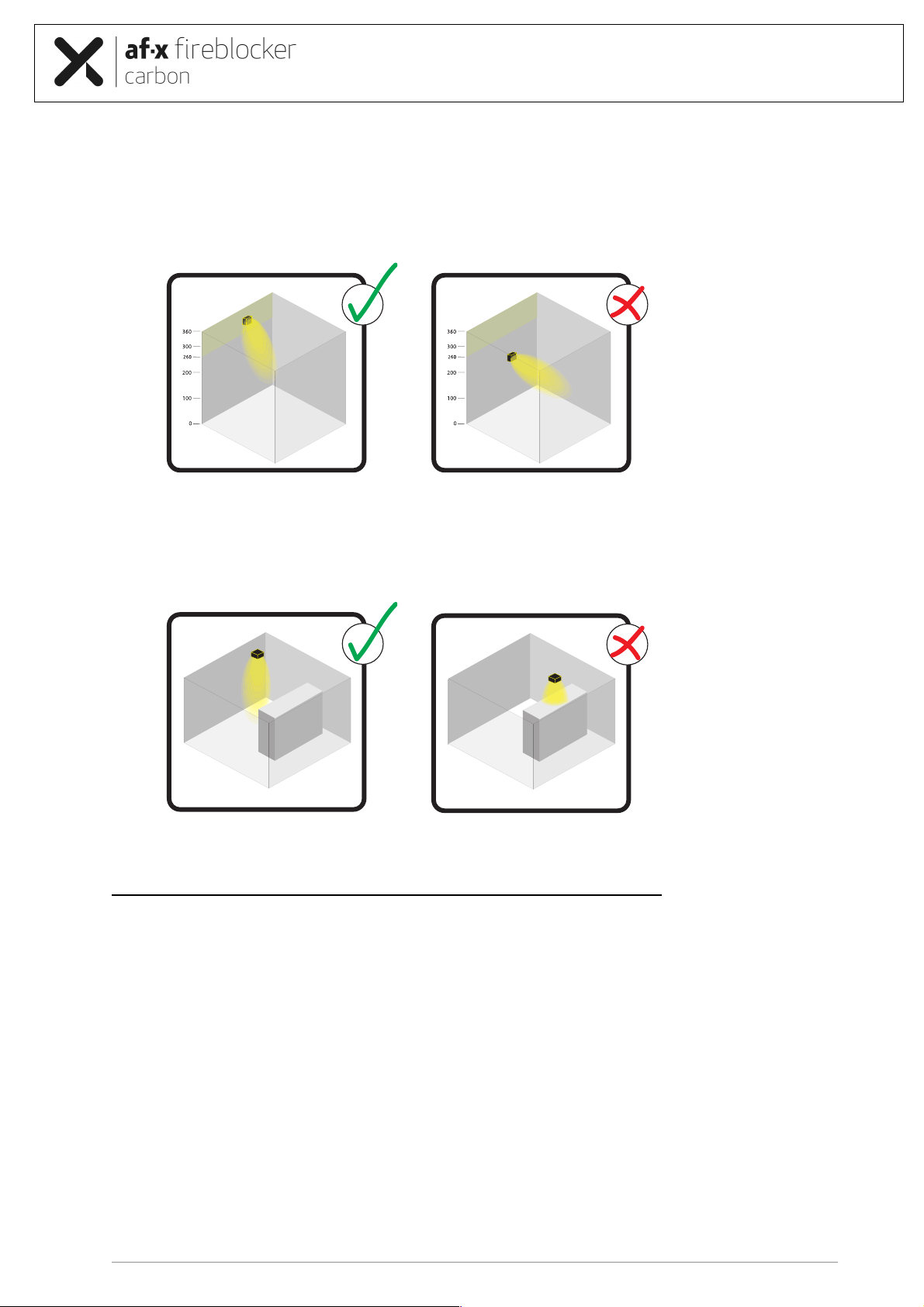
7. In an area higher than 1m, generators should preferably discharge downwards at an angle (cf. drawing).
Downward discharge in areas higher than 1m:
Please keep this user manual for future use. It will expire upon
publication of a revised issue. The latest version is available with your
distributor, dealer or at AF-X Systems BV.
User Manual AF-X Fireblocker Carbon Based Fire Extinguishers version 2.2
14
8. In areas higher than 2m, generators should be placed in the meter of space directly below the ceiling.
For high area’s (e.g. higher than 8m), it may be advisable to work with two ‘installation rings’. Please
consult the AF-X Systems experts when designing systems for areas of such height.
High areas, placed within one meter below ceiling:
9. It is of the utmost importance that there are no obstacles in front of the discharge opening for a distance
of at least the length of the AF-X generator itself.
Avoid obstacles in front of discharge opening:
5.10 Mounting guidelines AF-X Fireblocker Carbon generators
Please note that the AF-X Fireblocker generators should be mounted in static environments.
a) Please study the entire systems’ projection plan carefully before mounting any generator.
b) Systems with a fire extinguishing control panel should at all times contain a maintenance switch separating
the extinguishing units from the control panel during installation as well future maintenance activities.
c) For the installation of cables use the cables sold and/or advised by AF-X Systems only and make sure that
they are installed neatly, systematically and securely. Follow the cable manufacturer’s guidelines regarding
the installation of cables closely.
d) De AF-X Fireblocker generators are standard equipped with an IP55 connector chassis with a female inlay
(cf. product drawing). Using the proper tools, the installer must equip the control cable with a cable gland,
a hood and a male inlay, that AF-X Systems supplies.
e) The male insert is properly connected to the (massive core) control cable with a stripping length of 15mm
to pole number 1 and pole number 2, using a maximum torque of 0,5 Nm. The AF-X Fireblocker is not
earthed.

Please keep this user manual for future use. It will expire upon
publication of a revised issue. The latest version is available with your
distributor, dealer or at AF-X Systems BV.
User Manual AF-X Fireblocker Carbon Based Fire Extinguishers version 2.2
15
f) De AF-X Fireblocker generators must be mounted in isolation (even if the Statement of Requirement does
not specify as such). Attach the mounting brackets, which need to comply with local rules and regulations,
to the wall, ceiling or other location, using the insulation glands and rings in all mounting holes that connect
the bracket to the mounting surface. Do this in such a way that the extinguishing units cannot move or get
damaged inadvertently.
g) Take the AF-X Fireblocker from its packaging. Check the product for visible faults or damage as a result
of transport, etc. Take the AF-X Fireblocker from its packaging. Check the product for visible faults or
damage as a result of transport. Some generators are packed with nozzle protection brackets and
stickers. Remove them carefully and completely to assure the free outflow of aerosol during activation.
h) The AF-X Fireblocker is delivered with a short circuit safety between the poles 1 and 2 of the female inlay
in the connector. This prevents unwanted currents in the activation unit. To assure a secure and safe
installation of the generator, please keep the short circuit safety as long as possible in its safeguarding
position.
i) The cylindrical AF-X Fireblockers (Type CS and CM) are delivered with a protection cover on the nozzle.
After unpacking remove the protection cover.
j) Check whether the electric circuit of the AF-X Fireblocker generators is intact with an ohmmeter with an
accuracy of at least 2.5%. The resistance must be between 6.1 and 7.5 Ohm.
The test current should not exceed 20 mA for a maximum of 300 seconds.
k) Attach the AF-X Fireblocker firmly to the mounting brackets with the clasp and ensure an unobstructed
discharge. It is very important that there be no obstacle in the space immediately in front of the discharge
for a distance of at least the length of the AF-X Fireblocker generator itself (cf. drawing above). Always
maintain distance to cable ducts. Although the AF-X aerosol’s discharge temperature should not be
damaging to the cables, it is important that the discharge cannot be influenced. The correct distance at
which this unit must be installed is to be found on page 20 in annex 1.
l) The MCU Monitoring and Control unit is specially developed for application at Kentec Sigma XT, AX-T or
the Honeywell Notifier RP1r-SURPA panels. The connection will be displayed in the image on page 9.
m) Before attaching the AF-X Fireblocker connector, check whether the cables have been connected to the
disabled maintenance switch correctly (red LED on the maintenance switch is on), and whether the
maintenance switch has been connected to the Fire extinguishing control panel correctly.
n) Connect the power supply to the appropriate parts of the fire extinguishing system.
o) Check whether the Fire extinguishing control panel functions properly.
p) Check whether all requirements in this manual have been met.
q) The final step is to switch the maintenance switch(es) to ‘on/active’ (red LED is off)

Please keep this user manual for future use. It will expire upon
publication of a revised issue. The latest version is available with your
distributor, dealer or at AF-X Systems BV.
User Manual AF-X Fireblocker Carbon Based Fire Extinguishers version 2.2
16
6.0 Product Label
Example: AF-X Fireblocker Carbon CS label
Label information:
- General instructions and warning message
- 75°C outflow border
- Equipment type
- Model
- Mass of aerosol forming compound
- Operating temperature range
- Storage humidity range
- EN2 Class of Fire
- Contact details manufacturer
Every product also holds a metallized checker ‘production label’ containing the following information:
- Details of the fabrication location
- Serial number
- Month & year of production
7.0 Storage and transport
During transport and storage, the AF-X Fireblocker Carbon Series needs to be put up and protected against dirt,
moisture and precipitation.
The AF-X Fireblocker Carbon Series needs to be stored in its original packaging in racks in warehouses (either
heated or unheated, clean and well ventilated). Keep the AF-X Fireblocker Carbon Series away from heat sources
such as radiators, stoves, electric heaters and other heating appliances.
Storage conditions:
Temperature : between -20°C and +50°C
Relative humidity : maximum 90 % (relative humidity)
Beware: Do not drop the AF-X extinguishing units during loading and unloading.
Make sure that the labels on the packaging are correct and visible.

Please keep this user manual for future use. It will expire upon
publication of a revised issue. The latest version is available with your
distributor, dealer or at AF-X Systems BV.
User Manual AF-X Fireblocker Carbon Based Fire Extinguishers version 2.2
17
8.0 Maintenance of the AF-X Fireblocker
For the duration of its use the AF-X Fireblocker must be subjected to the following inspections and maintenance,
performed by qualified, i.e. in accordance with local laws and norms, technical staff:
• Check the extinguishing unit for any damage
• Check whether the sticker on the discharge opening is still secure
• Check the log
• Measure the resistance
• Check whether the projection is in accordance with delivery
• Check the mounting brackets and attachment
• Check whether the label on the extinguishing unit is securely fastened
• Check the unit’s life span, see expiry date on the label of the AF-X Fireblocker
NB the entire system, including all parts, must be checked regularly in accordance with the suppliers’ guidelines
and/or local laws.
The AF-X Fireblocker Carbon series have been designed for a service life of 15 years. Please be aware that
the extinguishant contains materials that have a relatively low melting temperature. These materials increase
the extinguishant’s efficiency, but it is therefore important to always ensure that the AF-X Fireblocker is not exposed
to temperatures that are outside the normal operating temperature range of -20 and + 50 degrees Celsius, as
stipulated in this manual. The service life of the AF-X Fireblocker is monitored by the producer by testing product
batches on a regular basis.
9.0 Residue removal, disassembly, waste and the environment
9.1 Introduction
Upon activation, the SAFCO converts into rapidly dispersing aerosols, consisting of solid micro particles suspended
in gas.
The concentration of solid particles suspended in the aerosol phase is a few milligrams per m³. The particles are
water and moisture-free and, after passing the hold-time, settle as dust in the protected area. The dust should be
removed before it absorbs moisture.
Thorough cleaning by removing all aerosol particles prevents the aerosol and combustion residue suspended in the
air from absorbing moisture so the particles cannot react any longer to electronic parts, metals, etc.
Should the aerosol particles remain on the surfaces for an extended period of time, they might absorb moisture,
thus risking a reaction of the moisture to metals (particularly uncoated metals), possibly resulting in oxidation.
After activation it is recommended to have delicate metals and equipment cleaned by a specialised company.
9.2 Residue removal
See and follow chapter 7 of the SDS that is added as Annex 3 to this manual for necessary personal protection
before entering the room.
- Although the aerosol in itself is harmless, ventilate the area for at least 30 minutes after activation. Do not
enter the area until after it is sufficiently ventilated.
- To avoid any unwanted side effects, remove the residue (within a couple of hours).
- Vacuum the dry residue from the floor and metals using a vacuum cleaner.
- Dust the residue from electric parts using a fan or ventilator.
- Use special sprays or dry ice cleaning suitable to remove residue from electronic parts.
NB although the residue is harmless to man and the environment, it is recommended to wear a dust
mask during cleaning activities because of particulates.
Always contact your distributor or dealer after AF-X Fireblocker activation; they will assist you in
renewed projection as well as the correct reconditioning and cleaning methods of the area
concerned

Please keep this user manual for future use. It will expire upon
publication of a revised issue. The latest version is available with your
distributor, dealer or at AF-X Systems BV.
User Manual AF-X Fireblocker Carbon Based Fire Extinguishers version 2.2
18
9.3 Disassembly after the AF-X Fireblocker has been activated
Please take the following steps when disassembling the activated AF-X Fireblocker Carbon Series:
Fully disconnect the unit from the fire detection system and make sure that it cannot be reconnected
inadvertently;
Disconnect the AF-X Fireblocker power supply wires and make sure they cannot be reconnected;
After activation the AF-X Fireblocker may still be hot; it is therefore recommended to wear heat
resistant gloves.
Be careful of your footing and observe local regulations concerning working
at height;
Unscrew the bolts and nuts holding the AF-X Fireblocker in the mounting bracket;
Gently take the AF-X Fireblocker out of its mounting bracket and place it on a stable base;
Upon the AF-X Fireblocker(s)’ disassembly consult with the manager about reactivating the fire
detection and alarm system;
9.4 Disassembly of an AF-X Fireblocker unit.
Please take the following steps when disassembling a working AF-X Fireblocker unit when it has to be replaced or
removed in a new configuration design, or when it has surpassed its operational life span.
a) Before any other activity, assure that the maintenance switch is switched to off
(Note: the red LED on the maintenance switch is ON if the system is off-line).
b) Disconnect the power supply cable from the unit.
c) Short-circuit the unit by connecting entrance #1 with entrance #2 in the connector.
d) Gently remove the Fireblocker out of its mounting bracket and place it on a stable base.
e) Further follow all instructions for storage and transport as described in chapter 6 and the Safety Data
Sheet that is Annex 4 of this manual.
9.5 Waste and the environment
After activation and subsequent disassembly, the AF-X Fireblocker can be handed in to a registered waste processing
company in accordance with local laws and regulations. In case the extinguishing units have not been activated and
the extinguishing agent is still present in the AF-X Fireblocker, the extinguishing units may be handed in to the AF-
X distributor or one of its dealers.
The packaging from the AF-X Fireblocker as well as the protection cover can be disposed as ordinary waste.
10.0 CE-Marking
Declaration of Conformity:
We herewith declare under our responsibility that the product AF-X Fireblocker Carbon Series where this statement
(CE) refers to, is in conformity to the RoHS Directive 2011/65/EU in conjunction with the harmonised standards
or technical specifications of EN 50581:2012.
The CE process and documentation has been supervised and approved by Certification Company.
EU Declaration of Conformity: No. 2017/728-01

Please keep this user manual for future use. It will expire upon
publication of a revised issue. The latest version is available with your
distributor, dealer or at AF-X Systems BV.
User Manual AF-X Fireblocker Carbon Based Fire Extinguishers version 2.2
19
Annex 1 General Technical Data
Model
Carbon CS
Carbon CM
Carbon BS
Carbon BM
Carbon BL
Gross weight extinguishing agent
in grams
720
1,440
4,800
9,600
14,400
Net weight extinguishing agent in
grams
317
634
2,112
4,224
6,336
Fire Classes
A & B
A & B
A & B
A & B
A & B
Activation mechanism
heating element with 6.1 – 7.5 Ohm resistance
Activation current
1.5 Ampère for 1 - 2 seconds, 12/24 Volt DC
Test current
< 0.02 Ampère within x minutes
Gross weight in kilograms
2.7
4.0
14.2
18.7
29.4
Casing
Steel
Steel
Steel
Steel
Steel
Shape
Cylinder
Cylinder
Square
Square
Square
Dimensions in mm
94⍉"x310
94⍉x450
250x250x213
250x250x304
250x250x457
Outflow time in seconds
< 60s
< 60s
< 120s
< 120s
< 120s
Outflow Length in meters
(projection)
> 3m
> 5m
> 4m
> 6m
> 8m
Discharge openings
1
1
1
1
1
Minimum installation height
25cm
25cm
50cm
50cm
50cm
Maximum installation height in
centimetres (coverage)
3m
5m
4m
6m
8m
Outflow length max. temperature
75°C
< 1m
< 1m
< 2m
< 2m
< 2m
Outflow length max. temperature
200°C
< 25cm
< 25cm
< 50cm
< 75cm
< 100cm
Outflow length max. temperature
400°C
< 0 cm
< 0 cm
< 0 cm
< 0 cm
< 0 cm
NB:The system design and applicability per m3 of the AF-X Fireblocker extinguishers are prescribed
by the manufacturer, recorded in the systems log and cannot be changed by third parties without loss
of warranty.

Please keep this user manual for future use. It will expire upon
publication of a revised issue. The latest version is available with your
distributor, dealer or at AF-X Systems BV.
User Manual AF-X Fireblocker Carbon Based Fire Extinguishers version 2.2
20
Annex 2 General technical data Bimetal Switch
This manual suits for next models
5
Table of contents
Other AFX Fire Extinguisher manuals


