AFX Fireblocker Nano Series User manual

1
User Manual AF-X Fireblocker November 2015 version 1
Design, Installation, Operation and Maintenance Manual
AF-X Fireblocker Nano Series
Date: 01-09-2020
Version: 3.5

Please keep this user manual for future use. It
will expire upon publication of a revised issue
however, so please check when using this manual
if you have the latest available version.
You can check with your distributor, dealer,
AF-X Systems BV or on the website:
www.af-x.com
User Manual AF-X Fireblocker Nano Series version 3.5
2
Design, Installation, Operation and Maintenance Manual
AF-X Fireblocker Nano Series
Version : 3.5
Date : 01-09-2020
Author : AF-X Systems BV
Published by : AF-X Systems BV
Grasweg 49
1031 HX Amsterdam
The Netherlands
Telephone : +31 (0)20 – 20 50 484
Homepage : www.af-x.com
E-mail : Info@af-x.com
Lay-out : In accordance with NEN-5509
This manual is the manufacturer’s design, installation, operating and maintenance instruction manual for detailed
instructions for correct usage and maintenance.
Please read this user manual carefully before installing
AF-X Fireblocker fire extinguishers of the Nano Series.
The AF-X Systems BV general terms and conditions can be retrieved at the Chamber of Commerce, Amsterdam
office, reference number 52010430
Copyright©
All rights reserved. Nothing in this publication may be reproduced and/or made public by means of printing,
photocopying, microfilm or any other method without prior written consent from AF-X Systems B.V.
It is permitted to offer this manual to stakeholders for inspection.
ã2020 AF-X Systems B.V.

Please keep this user manual for future use. It
will expire upon publication of a revised issue
however, so please check when using this manual
if you have the latest available version.
You can check with your distributor, dealer,
AF-X Systems BV or on the website:
www.af-x.com
User Manual AF-X Fireblocker Nano Series version 3.5
3
Design, Installation, Operation and Maintenance Manual
Contents
Signs to indicate prohibitions, mandatory actions and cautions used in this manual . 4
Foreword....................................................................................................... 5
1.0 Introduction ...........................................................................................6
2.0 Scope ....................................................................................................6
3.0 Design of the AF-X Fireblocker ..................................................................7
4.0 Precautions and safety instructions ............................................................7
5.0 Design and installation of a standalone system with one generator.................8
5.1 Design and installation of a multiple generator system .................................8
5.2 AF-X MCU (Monitoring & Control Unit) ........................................................9
5.4 AF-X Fireblocker design parameters ...........................................................9
5.5 AF-X Fireblocker Aerosol behaviour ............................................................9
5.6 Calculation of quantity and type .............................................................. 10
5.7 Projection of the generators within the area .............................................. 11
5.8 Mounting guidelines AF-X Fireblocker extinguishing generators .................... 14
5.9 Measures after activation of the extinguishing system ................................ 15
6.0 Storage and transport............................................................................ 15
7.0 Maintenance of the AF-X Fireblocker ........................................................ 16
7.1 Maintenance task for the user of the AF-X Fireblocker system...................... 16
8.0 Residue removal, disassembly, waste and the environment......................... 17
8.1 Introduction ......................................................................................... 17
8.2 Residue removal ................................................................................... 17
8.3 Disassembly after the AF-X Fireblocker has been activated.......................... 17
8.4 Replacement of an AF-X Fireblocker unit................................................... 18
8.5 Waste and the environment .................................................................... 18
9.0 CE-Marking........................................................................................... 18
Annex 1 General Technical Data .......................................................................... 19
Annex 2 AF-X Fireblocker Production Label ............................................................ 20
Annex 3 Safety Data Sheet ................................................................................. 21
Please keep this user manual for future use. It
will expire upon publication of a revised issue
however, so please check when using this manual
if you have the latest available version.
You can check with your distributor, dealer,
AF-X Systems BV or on the website:
www.af-x.com
User Manual AF-X Fireblocker Nano Series version 3.5
4
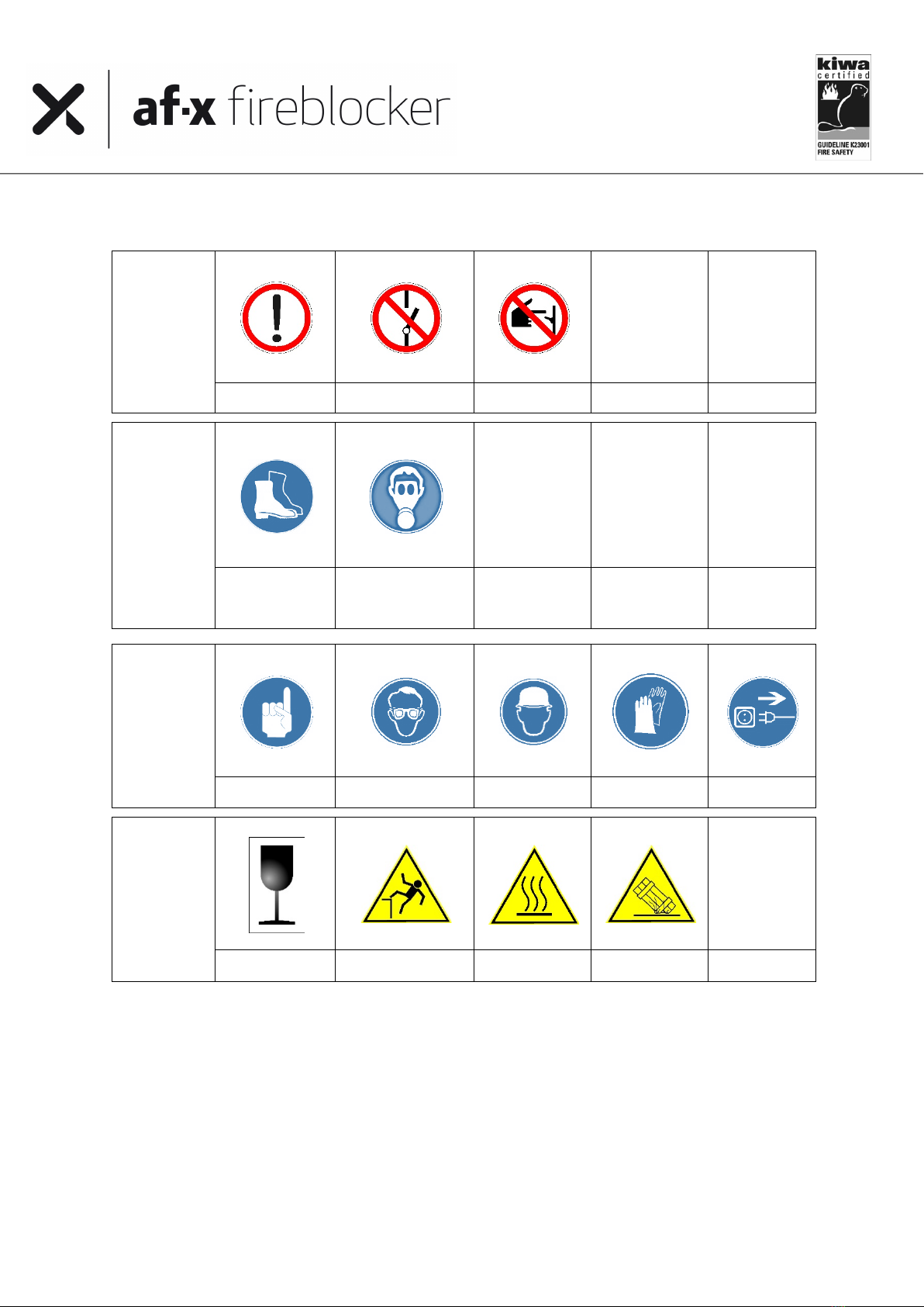
Signs to indicate prohibitions, mandatory actions and cautions used in this manual
PROHIBITION
Beware
No switching off
No switching on
MANDATORY
ACTION
Foot protection
respiratory
protection
MANDATORY
ACTION
Attention /
important
Eye protection
Head
protection
Hand
protection
Unplug /
disconnect
CAUTION
Fragile
Fall danger
Hot surface
Damage

Please keep this user manual for future use. It
will expire upon publication of a revised issue
however, so please check when using this manual
if you have the latest available version.
You can check with your distributor, dealer,
AF-X Systems BV or on the website:
www.af-x.com
User Manual AF-X Fireblocker Nano Series version 3.5
5
Foreword
Trademarks
af-x®, af-x fireblocker®and af-x systems®are registered trade, word and figurative marks.
Patents
AF-X Systems BV has registered several patents, including the patent for ‘Fire Extinguishing Composition’ under
number PCT/NL2012/050079.
Information on standards, directives and regulations
Various authorities issue directives regarding the use and installation of aerosol fire extinguishing systems.
Examples are the Kiwa certification schemes BRL-K23001, K23003 and ISO15779, EN15276-2, NFPA 2010 and
other NFPA Standards. Furthermore, there are often local directives, guidelines or regulations.
The standards in this user manual contain stipulations that, through the mere fact that they are being referred to,
serve as this document’s stipulations too. When this document went to print, the editions mentioned were in force.
All standards can be subject to revision however; parties entering into agreements based on this document are
therefore recommended to ascertain that they are using these standards’ latest versions.
AF-X Fireblocker has been designed, developed and built in accordance with the guidelines of the following
standards:
• International standards: ISO 15779
• European standards: CEN/TR 15276
• US standards: UL 2775 and NFPA 2010
• International Waters: IMO 1270
• Transport of Dangerous Goods: ADR, UN-No. 3268, Safety Devices, UN Class 9
• CE Marking: EU Pyrotechnic Directive 2013/29, category P1
The AF-X Fireblockers are delivered with the mandatory CE Marking according the Pyrotechnic Directive 2013/29.
An AF-X Fireblocker must be installed, inspected and maintained by qualified personnel with a minimum age of 18
years in compliance with local laws and regulations for installation and use of aerosol units and fire extinguishing
systems.
Information on general use of condensed aerosol generators
AF-X Fireblocker generators are intended for total flooding use where there is a fixed enclosure around the hazard
in order to enable the required concentration to be achieved and maintained for the required period of time and
therefor to ensure an effective extinguishment of a fire within the enclosure. They are intended for normally
unoccupied applications.

Please keep this user manual for future use. It
will expire upon publication of a revised issue
however, so please check when using this manual
if you have the latest available version.
You can check with your distributor, dealer,
AF-X Systems BV or on the website:
www.af-x.com
User Manual AF-X Fireblocker Nano Series version 3.5
6
1.0 Introduction
AF-X Fireblocker is designed to extinguish surface burning fires Class A&B. This manual is written in such a way that
it covers most of the important aspects of the AF-X Fireblocker’s functional use. Therefore, to ensure functional use
of the AF-X Fireblocker, all instructions of this manual need to be followed closely.
Electrical installations, such as fire detection, control and alarm systems, need to be designed, installed and
maintained by the systems supplier trained (certified) personnel according to this manual and instructions. Local or
National standards, guidelines or other legislation regarding these matters are not included in this user manual.
The aerosol generated, may create a potential hazard for personnel and equipment in the protected area. While
generating aerosol, there are high temperature products of the extinguishing media discharged and this
characteristic should be evaluated before the generators are installed.
In case of incorrect use of the information in this manual AF-X Systems BV will not accept any responsibility for any
damage caused by the AF-X Fireblocker system.
2.0 Scope
AF-X Fireblocker is based on a condensed aerosol and designed to be part of a total flooding fire extinguishing
system. Precondition for powerful performance is the unit’s connection to and activation by an effective fire detection
system. Rapid detection and reaction are vital.
AF-X Fireblocker can be used in spaces that are normally unoccupied. Cylindrical generators can additionally be
placed in motor compartments or otherwise vibrating environments.
AF-X Fireblocker and other aerosol extinguishants have been recognized as effective media for the extinction of
Class A fires (solid surface burning fires) and Class B fires according to EN 2 but it should not be forgotten, in the
planning of comprehensive schemes, that there can be hazards for which these mediums are not suitable, or that
in certain circumstances or situations there can be dangers in their use requiring special precautions.
AF-X Fireblocker cannot be used with:
• Materials with non-surface burning fire potential, or possible chain reaction of the organic fuel, oxygen and
temperature within the material(s), bulk smouldering fire potential, e.g. in cocoa beans, rubber;
• Oxygenic chemical compounds such as nitrocellulose and gunpowder;
• Reactive metals such as lithium, sodium, potassium, magnesium, titanium, zirconium, uranium and
plutonium;
• Metal oxides;
• Organic peroxides and hydrazine
This list may not be exhaustive

Please keep this user manual for future use. It
will expire upon publication of a revised issue
however, so please check when using this manual
if you have the latest available version.
You can check with your distributor, dealer,
AF-X Systems BV or on the website:
www.af-x.com
User Manual AF-X Fireblocker Nano Series version 3.5
7
3.0 Design of the AF-X Fireblocker
General description of the AF-X Fireblocker:
1) The AF-X Fireblocker has a stainless-steel casing and comes in various shapes and sizes see annex 1.
2) The AF-X Fireblocker contains a solid, aerosol-forming compound (“SAFCO”).
3) Each container is equipped with a special system for independent activation of the AF-X Fireblocker.
4) All types are equipped with a heat absorbing mechanism (insulation).
A tension of 6-36 V (Direct Current) on the AF-X Fireblocker and an electric current of at least 1,0 amperes for 1-2
seconds activates the extinguishing agent and convert it into dispersed nano particles. The aerosol is then cooled
by the heat absorbing elements and discharged into the protected area, blocking the fire by stopping the combustion
chain reaction. Activation simultaneously triggers other chemical reactions ensuring a final product that is harmless
to man, matter and the environment.
Schematic illustration of the AF-X Fireblocker with its 6 key components:
1. Connector to ensure quick installation
2. Patented extinguishing agent to ensure rapid and effective fire extinguishing
3. Activator
4. Balanced space to ensure optimum action and interaction.
5. Thermodynamic cooling to ensure a controlled efflux temperature
6. Aerodynamic discharge opening to ensure a quick and optimum dispersal in the protected area
4.0 Precautions and safety instructions
Read this user manual carefully before putting the AF-X Fireblocker into use.
This user manual contains precaution and safety instructions to ensure a safe execution of the necessary steps. The
term ‘steps’ may refer to all actions in the various product phases: transport, receipt, storage, assembly, connection
of the product, mounting and/or installation, treatment and/or use, maintenance, visual inspection, repairs,
decommissioning, disassembly, removal, disposal, waste, health, safety and the environment.
Please keep this user manual for future use. It
will expire upon publication of a revised issue
however, so please check when using this manual
if you have the latest available version.
You can check with your distributor, dealer,
AF-X Systems BV or on the website:
www.af-x.com
User Manual AF-X Fireblocker Nano Series version 3.5
8
Warning: the AF-X Fireblocker may only be installed, maintained or serviced by technically qualified
and trained persons and in accordance with the latest applicable local laws, regulations and
standards.
When working with the AF-X Fireblocker it is prohibitedto:
- open and/or dismantle extinguishing units;
- by any means apply force to the units that could result in distortion, physical or mechanical
damage to the casing;
- carry out welding activities in the vicinity of the AF-X Fireblocker extinguishing units;
- smoke in the vicinity of the AF-X Fireblocker extinguishing units.
In case an extinguishing unit has fallen, it should be checked for damage to the activator’s electric
switch and/or other components. When damage and/or dysfunction cannot be ruled out with
certainty, the unit cannot be used and must be returned to the authorised AF-X distributor or dealer.
Please see to it that all legal requirements, regulations and advice are adhered to. Pay attention
to the risks involved in working at height. Be careful of your footing and use reliable tools and
proper personal protective equipment. Should you have any queries, please consult your employer
and/or qualified consultancy agencies.
To avoid unnecessary exposure of occupants to the discharged extinguishant, factors such as the time
for egress and the risk to the occupants by the fire should be considered when determining the system
discharge time delay. Where national standards require other precautions, these should be implemented
5.0 Design and installation of a standalone system with one generator
A standalone AF-X Fireblocker generator can be activated by means of a thermal circuit. For this the AF-X Bimetal
Switch can be used. A standalone system cannot be larger than the max coverage volume of the generator.
Please note that equipment used for heating or welding, and other sources of energy, might provoke
activation of the fire extinguishing generator if the self-activation temperature is of 300 ºC will be reached.
5.1 Design and installation of a multiple generator system
The fire extinguishing system’s basic design determines which detection system and/or peripheral equipment will
be chosen. Please be aware that local rules and regulations or a certifying authority may require specific
equipment. For proper installation of the systems we expressly refer to the information in this DIOM and to the
Fire detection and fire alarm systems manufacturers installation requirements.
The minimum standard requirements for an aerosol fire extinguishing system with multiple extinguishing
generators are:
1. The Fire Extinguishing Control Panel FECP (whether or not connected to a Fire Alarm System, FAS) which
connects, supplies power to, monitors and controls the various components of the extinguishing system must
comply to CEN/TS 54-14, Fire detection and fire alarm systems - Part 14: Guidelines for planning, design,
installation, commissioning, use and maintenance or to similar local legislation, guidelines and / or standards;
2. The Fire Extinguishing Control Panel FECP must be able to provide sufficient energy to activate all the
generators in the system and as designed;
3. Unless otherwise specified in a standard, 72 h minimum standby sources of energy shall be used to provide
for operation of the detection, signalling, control and actuation requirements of the system.
4. Fire detection and fire alarm system must be able to generate acoustical and optical signals to warn or inform
people present in the protected area about the current status;
5. Wiring, components and connectors connecting the various parts of the system must meet the relevant part
of EN54 or similar.

Please keep this user manual for future use. It
will expire upon publication of a revised issue
however, so please check when using this manual
if you have the latest available version.
You can check with your distributor, dealer,
AF-X Systems BV or on the website:
www.af-x.com
User Manual AF-X Fireblocker Nano Series version 3.5
9
6. Automatic detection equipment feeding the FECP shall be by any method or device and shall be capable of
early detection and indication of heat, flame, smoke, combustible vapours, or any abnormal condition in the
hazard that is likely to produce fire, and meets the minimum requirements in the table below:
Type of application
Type of protection
Number of criteria
Detection of
Activation criteria
Room
Total flooding
3
CO, heat and smoke
2 detectors or 2 groups
Object / cabinet
Total flooding
2
CO and heat
Specific
See protocol
See protocol
See protocol
Note: Specific conditions and / or special applications shall always be verified by AF-X systems.
There are many fire extinguishing systems on the market. When selecting a FECP it is important to consider the
local rules and regulation concerning fire extinguishing systems in general and aerosol fire extinguishing systems
in particular.
Note that the extinguishing generators are activated by a heating element with 1.3 – 3.2 Ohm resistance.
The required electric activation voltage is 6 -36 Volt DC; 1.0 Ampère (= 1000 mA) for 1-2 seconds.
5.2 AF-X MCU (Monitoring & Control Unit)
The extinguishing generators are activated by a heating element with 1.3 – 3.2 Ohm resistance. The required electric
activation voltage is 6 -36 Volt DC; 1.0 Ampère (= 1000 mA) for 1-2 seconds.
In order to assure that the activation power of the Fire Extinguishing Control Panel FECP is distributed correctly
throughout the multiple generator system, the monitoring and control units were developed.
The AF-X MCU provides connection from the Kentec XT, AX-T or the Honeywell Notifier RP1r-SURPA fire control
panel to the AF-X Fireblockers.
• A maximum of 18 AF-X MCU’s can be connected to each extinguishing line,
• A maximum of 2 AF-X Fireblockers on each MCU.
5.4 AF-X Fireblocker design parameters
For the correct design of an AF-X Fireblocker system, the following steps must be taken:
1. Calculation of the required quantity and type of extinguishing generators;
2. Projection of the extinguishing generators correct position in the area to be protected;
3. Determination of the extinguishing generators correct discharge direction.
5.5 AF-X Fireblocker Aerosol behaviour
For a correct design of an AF-X Fireblocker extinguishing system, it is important to consider several properties and
behavioural aspects of the AF-X Fireblocker Aerosol in the area to be protected.
The aerosol formed by the AF-X Fireblocker leaves the generator at some speed. This can be observed as a
spreading transparent-white cloud. The temperature of this cloud, consisting of extremely small nanoparticles, is
usually somewhat higher than its surroundings. So, initially the aerosol cloud and the temperature in the
enclosure will therefore seem to be slowly rising.
The particles are so small that gravity hardly affects them, and they can disperse in the air rapidly in a balanced
fashion. The currents and whirls present in the area, either caused by fire or just by the active equipment, make
that the tiny aerosol particles actively move through the area. The AF-X Fireblocker Aerosol has been designed to
make maximum use of these currents. By consequence, the convection currents caused by the seat of the fire
draw the particles into that seat. Even when the fire is just in its very early stages of development.

Please keep this user manual for future use. It
will expire upon publication of a revised issue
however, so please check when using this manual
if you have the latest available version.
You can check with your distributor, dealer,
AF-X Systems BV or on the website:
www.af-x.com
User Manual AF-X Fireblocker Nano Series version 3.5
10
5.6 Calculation of quantity and type
When you have the protected volume at hand you can use the AF-X Fireblocker Density Calculation Sheet to
determine the amount of extinguishant you need and which types of extinguishing generators to choose. This
Calculation Sheet is available for trained technicians upon request with AF-X Systems at all times.
The capacity of the generators below is already implemented in the calculation sheet
Coverage Model and Temperature Curve
n-CS
n-CM
n-BM
n-BL
Minimum installation height (horizontally) in cm
Area coverage based on density
30
30
100
100
Maximum installation height in cm
Area coverage based on density
150
150
500
800
Outflow length in cm
150
150
500
600
Outflow length max. temperature 75°C in cm
< 100
< 150
150
200
Outflow length max. temperature 200°C in cm
Does not
occur
Does not
occur
< 50
150
Outflow length max. temperature 400°C in cm
Does not
occur
Does not
occur
Does not
occur
< 100
Design density calculation
Manual calculation of the design density can be done using the following formula used in EN15276-2 and NFPA
2010:2015
The effective mass of aerosol in the system shall be at least sufficient for the largest single hazard or group of
hazards that are to be protected against simultaneously.
The mass of extinguishant required to achieve the design application density shall be calculated from Formula:
M = ρ×V
where
mis the total flooding quantity, in g;
ρis design application density, in g/m3 (may need to be adjusted to compensate for any special conditions that
would adversely affect the extinguishing efficiency, consult AF-X Systems);
Vis protected volume, in m3 (may include adjacent connected hazards or work areas).
The design density is the extinguishing density multiplied by the mandatory safety factor of 1.3
In addition to these calculated total flooding quantities, additional quantities of extinguishant can be required by
standards to compensate for any special conditions that would adversely affect the extinguishing efficiency or, if
required, by the physical characteristics of the extinguishant. Consult AF-X Systems in case of special environmental
conditions or applications.
AF-X Fireblocker generator size and quantity selection
In case of the need of more than one aerosol generator to protect a volume, preferably generators of the same
family should be used. In all cases the design shall be realized according to the determined coverage tests of the
AF-X Fireblocker generator(s) involved.
NOTE: As each condensed aerosol generator contains a distinct amount of the solid aerosol-forming compound,
there can be a few options in regard to the unit size and number of the aerosol generators that would be
adequate to achieve the required design quantity.

Please keep this user manual for future use. It
will expire upon publication of a revised issue
however, so please check when using this manual
if you have the latest available version.
You can check with your distributor, dealer,
AF-X Systems BV or on the website:
www.af-x.com
User Manual AF-X Fireblocker Nano Series version 3.5
11
The selected unit sizes should conform to the maximum distance and area coverage and maximum or minimum
protected height limitations as specified for each unit.
For example, in some applications such as cable ducts and trenches several smaller units of the same family
evenly spread along the protected enclosure would provide better distribution and faster achievement of the
minimum design application density throughout the area although one large unit can fulfil the agent quantity
requirement.
Quantity of aerosol generator’s units needed to protect a room can be increased in order not to exceed maximum
coverage distance.
Same unit size formula:
n = M/Mg
where
n is the rounded up integer number of aerosol generators of one size;
Mis the design quantity, in gram;
Mg is the mass of the aerosol-forming compound in one generator, in gram.
Different unit sizes:
The height of the protected enclosure should not exceed the maximum height limitation listed for the smallest unit
size selected, unless uniformity of the aerosol distribution for the greater height has been proved by a discharge
test.
5.7 Projection of the generators within the area
The following general criteria should apply:
Ø for locations, where personnel can be situated, the minimum thermal clearance should refer to the
temperature not exceeding 75 °C;
Ø for locations, where combustible materials or equipment can be situated, the minimum thermal clearance
should refer to the temperature not exceeding 200 °C;
Ø for locations, where non-combustible equipment can be situated, the minimum thermal clearance should
refer to the temperature not exceeding 400 °C.
There are a number of rules which are helpful to determine the best positions for the generators in a design.
These rules are based on standards and coverage tests, but each area is different. It is important to adhere to the
standards as much as possible. Needless to say, the distribution of generators in the area should also be in
accordance with local rules and regulations as well as the systems basic design.
a) Guidelines for the correct positioning and distribution in the area
1. AF-X Fireblocker Generators need to be positioned in such a way that the discharged aerosol will be
dispersed in the enclosures protected volume as quickly and homogenously as possible.
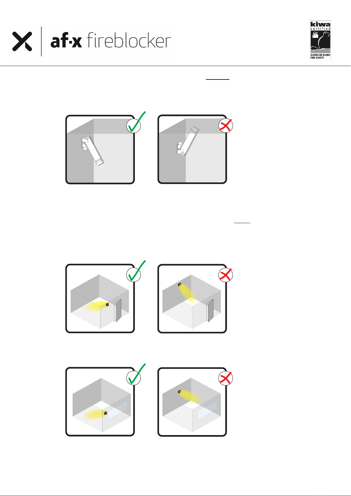
2. AF-X Fireblocker Generators are preferably mounted on the wall or at the ceiling, with the discharge
opening pointing downwards at an angle from the ceiling or wall as shown below.
3. The units need to be evenly distributed in the area.
One larger generator could be more effective than two smaller, the use of two generators could be more
effective than using four, but there are no absolutes. The deciding factor should be whether the chosen
number could fill the area with aerosol rapidly and evenly. After all, every nook and cranny must be filled
with sufficient aerosol.
When in doubt, do not hesitate to contact the AF-X experts.
Please keep this user manual for future use. It
will expire upon publication of a revised issue
however, so please check when using this manual
if you have the latest available version.
You can check with your distributor, dealer,
AF-X Systems BV or on the website:
www.af-x.com
User Manual AF-X Fireblocker Nano Series version 3.5
12
b) Guidelines for the determination of the correct discharge direction
4. Preferably, generators are mounted to the wall just under the ceiling with the discharge opening directed
downwards.
If a free downward outflow is not possible, the generators can be mounted on the ceiling, also with the
discharge opening directed downwards.
5. Generators need to be positioned in such a way that all discharged aerosol is dispersed unhampered and
in full in the area to be protected. This also implies that the generators always need to be projected
towards unobstructed space, away from windows, doors, grates, vents, lids, valves, man-holes, transom
windows or other openings. This includes openings that are usually closed or pushed closed with door-
closers or automatically by the FECP before extinguishing starts.
Away from doors:
Away from windows or other potential openings:
Please keep this user manual for future use. It
will expire upon publication of a revised issue
however, so please check when using this manual
if you have the latest available version.
You can check with your distributor, dealer,
AF-X Systems BV or on the website:
www.af-x.com
User Manual AF-X Fireblocker Nano Series version 3.5
13
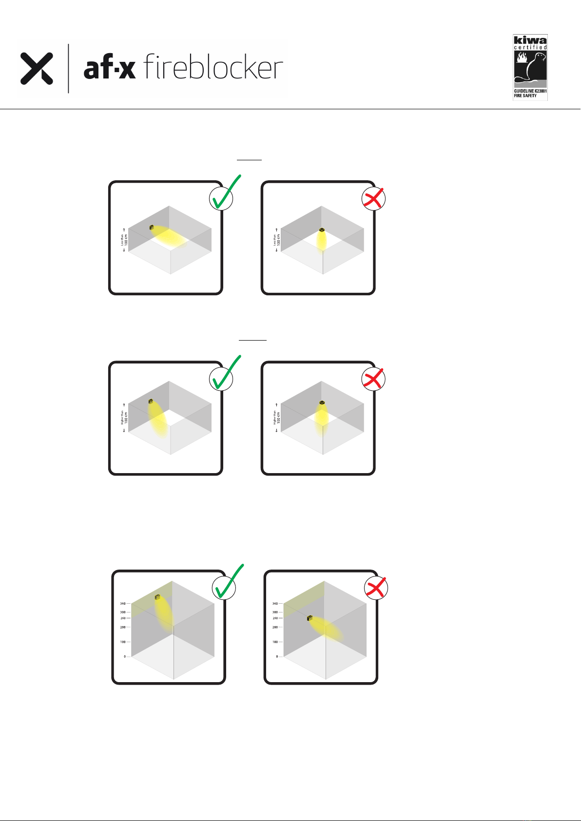
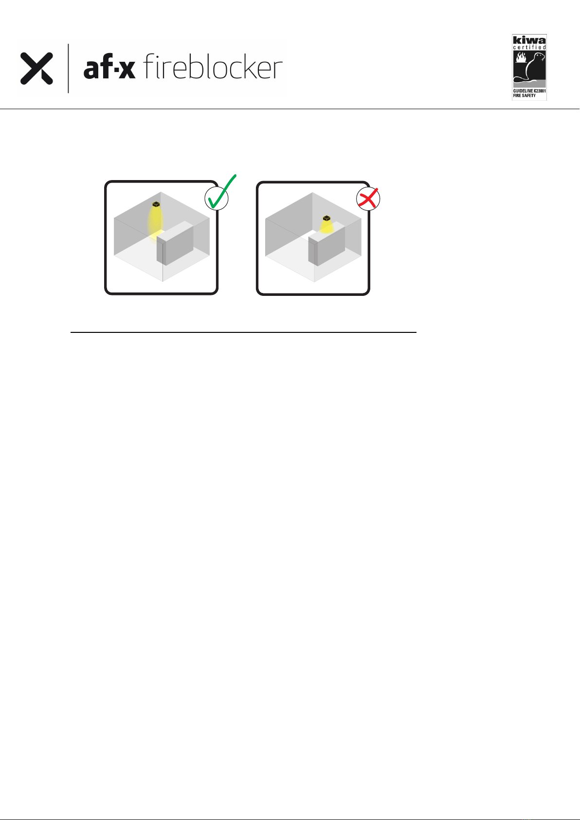
6. In an area with a height of less than 1m, generators should preferably discharge horizontally.
Horizontal discharge in areas lower than 1m:
7. In an area higher than 1m, generators should preferably discharge downwards at an angle (cf. drawing).
Downward discharge in areas higher than 1m:
8. In areas up to a hight of 8 m, generators should be placed in the meter of space directly below the
ceiling. For areas higher than 8 m, consult the AF-X Systems experts how to approach a design for a
system for enclosures of such height.
High areas placed within one meter below ceiling:
Please keep this user manual for future use. It
will expire upon publication of a revised issue
however, so please check when using this manual
if you have the latest available version.
You can check with your distributor, dealer,
AF-X Systems BV or on the website:
www.af-x.com
User Manual AF-X Fireblocker Nano Series version 3.5
14
9. It is of the utmost importance that there are no obstacles in front of the discharge opening for a distance
as specified in 5.6
Avoid obstacles in front of discharge opening:
5.8 Mounting guidelines AF-X Fireblocker extinguishing generators
Please note that the AF-X Fireblocker Box units should be mounted under normal environmental conditions.
a) Please study the entire system’s projection plan carefully before mounting any generators.
b) Systems with a fire extinguishing control panel should at all times contain a system isolating switch
separating the extinguishing units from the control panel during installation as well as during
maintenance activities.
c) For the installation of cables use the cables sold and/or advised by AF-X Systems only and make sure
that they are installed according standard or local guidelines/legislation. Always follow the cable
manufacturer’s guidelines regarding the installation of cables.
d) Take the AF-X Fireblocker from its packaging. Check the product for visible faults or damage as a result
of transport. Some generators are packed with nozzle protection brackets and stickers. Remove them
carefully and completely to assure the free outflow of aerosol during activation.
e) De AF-X Fireblocker generators are standard equipped with an IP55 female connector chassis (see
relevant product drawing). Using the proper tools, the installer must equip the control cable with a cable
gland, a hood and a male inlay, that AF-X Systems supplies.
f) The AF-X Fireblocker is delivered with a short circuit safety between the poles 1 and 2 of the female inlay
in the connector. This prevents unwanted currents in the activation unit. To assure a secure and safe
installation of the generator, please keep the short circuit safety as long as possible in its safeguarding
position.
g) The male insert is properly connected to the (massive core) control cable with a stripping length of
15mm to pole number 1 and pole number 2, using a maximum torque of 0,5 Nm. The AF-X Fireblocker is
not earthed.
h) De AF-X Fireblocker generators must be mounted in isolation glands and rings (even if the basic design
does not specify as such). Attach the mounting brackets, which need to comply with local rules and
regulations, to the wall, ceiling or other location, using the insulation glands and rings in all mounting
holes that connect the bracket to the mounting surface. Do this in such a way that the extinguishing
units cannot move or get damaged inadvertently.
i) Attach the AF-X Fireblocker firmly to the mounting brackets with the clasp and ensure an unobstructed
discharge. It is very important that there be no obstacle in the space immediately in front of the
discharge for a distance of at least the length of the AF-X Fireblocker generator itself (cf. drawing above).
Always maintain distance to cable ducts. Although the AF-X aerosol’s discharge temperature should not
be damaging to the cables, it is important that the discharge cannot be influenced.
Please keep this user manual for future use. It
will expire upon publication of a revised issue
however, so please check when using this manual
if you have the latest available version.
You can check with your distributor, dealer,
AF-X Systems BV or on the website:
www.af-x.com
User Manual AF-X Fireblocker Nano Series version 3.5
15
j) Before attaching the AF-X Fireblocker connector, check
Ø whether the cables have been connected to the disabled system isolating switch, and whether
the system isolating switch has been connected to the Fire extinguishing control panel correctly
and;
Ø whether the electric circuit of the AF-X Fireblocker generators is intact with an ohmmeter with
an accuracy of at least 2.5%. The resistance must be between 1.3 and 3.2 Ohm.
ü Any test current should not exceed 40 mA for a maximum of 300 seconds.
k) Connect the power supply to the appropriate parts of the fire extinguishing system.
l) Check whether the Fire extinguishing control panel functions properly.
m) Check whether all requirements in this manual have been met.
n) The final step is to switch the system isolating switch(es) to ‘on/active’
5.9 Measures after activation of the extinguishing system
If the extinguishing panel activates the AF-X Fireblocker generators, the aerosol will present itself as a white cloud
that is rapidly dispersed from the unit. This aerosol cloud will enter into stable connections on a molecular level with
the free radicals that, as a catalyst, accelerate the fire reaction.
a) If extinguishing is in progress, indicated by alarm signals of the control panel or otherwise audible or
visible, the protected area should be kept closed for a minimum of 30 minutes. Though longer is better, as
it will allow for heated materials to cool down to safe temperatures. Allowing air (with new free radicals)
to come into the protected area, might increase or restart the fire if temperatures are still (too) high.
b) After extinguishing please contact your dealer immediately so that proper advice on the reconditioning and
restoring of the protected area and the fire extinguishing system can be followed directly.
c) On the cleaning and reconditioning of the protected area after extinguishing more can be found in chapter
8, though it is always recommended to organize restoring and cleaning work of electronics or other delicate
equipment by specialized and trained organizations or staff.
6.0 Storage and transport
The AF-X Fireblocker are assigned to transport classification Class 9.0 as SAFETY DEVICES, electrically initiated
under UN number 3268
During transport and storage, the AF-X Fireblocker needs to be put up and protected against dirt, moisture and
precipitation. Please be aware that heavy shocks might cause some dust to be expelled through narrow slots of the
generator. This dust is not harmful for man and/or environment.
The AF-X Fireblocker needs to be stored in its original packaging in racks in warehouses (either heated or unheated,
clean and well ventilated). Keep the AF-X Fireblocker away from heat sources such as radiators, stoves, electric
heaters and other heating appliances.
Storage conditions:
Temperature: between -20°C and +50°C,
ideally storage conditions are between 18°C to 25°C. Please note that higher or lower
storage temperatures will have consequences for the lifetime.
Humidity: maximum 95 % (relative humidity)
Beware: Do not drop the AF-X extinguishing units during loading and unloading.
Make sure that the labels on the packaging are correct and visible.
Please keep this user manual for future use. It
will expire upon publication of a revised issue
however, so please check when using this manual
if you have the latest available version.
You can check with your distributor, dealer,
AF-X Systems BV or on the website:
www.af-x.com
User Manual AF-X Fireblocker Nano Series version 3.5
16
7.0 Maintenance of the AF-X Fireblocker
For the duration of its use the AF-X Fireblocker must be subjected to the following inspections and maintenance,
performed by trained and qualified, i.e. in accordance with local laws and standards, technical staff:
• Activate the system isolating switch
• Check the extinguishing unit for any damage
• Check whether the sticker on the discharge opening is still secure
• Check the log
• Measure the resistance between connector entrance #1 and #2
• Check whether the projection is in accordance with the basic design / as delivered condition
• Check the mounting brackets and attachment to the surface
• Check whether the label on the extinguishing unit is still securely fastened and readable
• Check the unit’s production date and service life span
This list may not be exhaustive
Note that the entire system, including all parts/components, must be checked regularly in accordance with the
supplier’s guidelines and/or local laws. International guidelines recommend performing monthly checks on the
following components, electric wiring, electric contacts, fixed bolts and generators casing.
Please be aware that the extinguishant contains materials that have a relatively low melting temperature. These
materials increase the extinguishant’s efficiency, but it is therefore important to always ensure that the AF-X
Fireblocker is not exposed to temperatures that are outside the normal operating temperature range of -10 and +
50 degrees Celsius, as stipulated in this manual. The service life of the AF-X Fireblocker is monitored by the
producer by testing product batches on a regular basis.
7.1 Maintenance task for the user of the AF-X Fireblocker system
The installer shall provide the user with an inspection programme for the system and components. The
programme should include instructions on the action to be taken in respect of faults.
The user’s inspection programme is intended to detect faults at an early stage to allow rectification before the
system may have to operate. A suitable programme is as follows.
a) Weekly: Visually check the hazard and the integrity of the enclosure for changes which might reduce the
efficiency of the system. Carry out a visual check that there is no obvious damage to cables and that all operating
controls and components are properly set and undamaged.
b) Monthly: Check that all personnel who may have to operate the equipment or system are properly trained and
authorised to do so and, in particular, that new employees have been instructed in its use.
WARNING — Always operate a system isolate switch prior to entering the protected enclosure if the unit is not
designed for occupied spaces.

Please keep this user manual for future use. It
will expire upon publication of a revised issue
however, so please check when using this manual
if you have the latest available version.
You can check with your distributor, dealer,
AF-X Systems BV or on the website:
www.af-x.com
User Manual AF-X Fireblocker Nano Series version 3.5
17
8.0 Residue removal, disassembly, waste and the environment
8.1 Introduction
Upon activation, the SAFCO converts into rapidly dispersing aerosols, consisting of solid nano and micro particles
suspended in gas.
The concentration of solid particles suspended in the aerosol phase is a few milligrams per m³. The particles are
water and moisture-free and after some time settle as dust in the protected area. The dust can easily be removed
before it absorbs moisture.
If thorough cleaning removes the aerosol particles before they can absorb moisture and combustion residue
suspended in the air, the particles cannot react to electronic parts, metals, etc.
Should the aerosol particles remain on the surfaces for an extended period of time, they might absorb moisture,
thus risking a reaction of the moisture to metals (particularly uncoated metals), possibly resulting in oxidation.
After activation it is recommended to have delicate metals and equipment cleaned by a specialised company.
8.2 Residue removal
See and follow chapter 7 of the SDS that is added as Annex 3 to this manual for necessary personal protection
before entering the room.
- Although the aerosol in itself is harmless, ventilate the area for at least 30 minutes after activation. Do not
enter the area until after it is sufficiently ventilated.
- To avoid any unwanted side effects, remove the residue (within a couple of hours).
- Vacuum the dry residue from the floor and metals using a vacuum cleaner.
- Dust the residue from electric parts using a fan or ventilator.
- Use special sprays or dry ice cleaning suitable to remove residue from electronic parts.
NB it is mandatory to wear a dust mask during cleaning activities because of particulates.
Always contact your distributor or dealer after AF-X Fireblocker activation; they will assist you in
renewed projection as well as the correct reconditioning and cleaning methods of the area
concerned
8.3 Disassembly after the AF-X Fireblocker has been activated
Please take the following steps when disassembling the activated AF-X Fireblocker:
Fully disconnect the unit from the fire detection system and make sure that it cannot be reconnected
inadvertently;
Disconnect the AF-X Fireblocker power supply wires and make sure they cannot be reconnected;
After activation the AF-X Fireblocker may still be hot; it is therefore recommended to wear heat
resistant gloves.
Be careful of your footing and observe local regulations concerning working
at height;
Unscrew the bolts and nuts holding the AF-X Fireblocker in the mounting bracket;
Gently take the AF-X Fireblocker out of its mounting bracket and place it on a stable base;
Upon the AF-X Fireblocker(s)’ disassembly, consult with the manager about reactivating the fire
detection and alarm system;

Please keep this user manual for future use. It
will expire upon publication of a revised issue
however, so please check when using this manual
if you have the latest available version.
You can check with your distributor, dealer,
AF-X Systems BV or on the website:
www.af-x.com
User Manual AF-X Fireblocker Nano Series version 3.5
18
8.4 Replacement of an AF-X Fireblocker unit.
Please take the following steps when replacing a AF-X Fireblocker unit when it has to be repositioned or removed
in a new configuration design, or when it has surpassed its operational service life span.
a) Before any other activity, make sure that the maintenance switch is activated, and the system is in-
active;
b) Disconnect the power supply cable from the unit;
c) Short-circuit the unit by connecting entrance #1 with entrance #2 in the connector.
A 1,5 mm2solid core wire may be used.
d) Gently remove the Fireblocker out of its mounting bracket and place it on a stable underground.
e) Further follow all instructions for packaging, storage and transport as described in chapter 6 and the
Safety Data Sheet that is Annex 3 of this manual. Use original or similar packaging with foam blocks and
necessary stickers.
8.5 Waste and the environment
After activation and subsequent disassembly, the AF-X Fireblocker can be handed in to a registered waste
processing company in accordance with local laws and regulations. In case the extinguishing units have not been
activated and the extinguishing agent is still present in the AF-X Fireblocker, the extinguishing units must be
handled by the AF-X distributor or one of its dealers. Please follow all instructions for packaging, storage and
transport as described in chapter 6 and the Safety Data Sheet that is Annex 2 of this manual. Use original or
similar packaging with foam blocks and necessary stickers.
9.0 CE-Marking
Declaration of Conformity of the AF-X Fireblocker aerosol generating fire extinguishers: We herewith declare under
our responsibility that the product AF-X Fireblocker as exclusively produced for AF-X Systems BV by Aerospace
Propulsion Products BV (part of Ariane Group), where to this statement (CE) refers, is in conformity to the Directives
2006/42/EG and 2013/29/EU of the European Parliament and of the Council. The CE marking and documentation
requirements has been supervised and approved by INERIS by certification number 0080.P1.18.0022

Please keep this user manual for future use. It
will expire upon publication of a revised issue
however, so please check when using this manual
if you have the latest available version.
You can check with your distributor, dealer,
AF-X Systems BV or on the website:
www.af-x.com
User Manual AF-X Fireblocker Nano Series version 3.5
19
Annex 1 General Technical Data
Model
CS
CM
BM
BL
Shape
cylindrical
cylindrical
Square
Square
Dimensions in mm
94⍉x300
94⍉x450
250x250x304
250x250x304
Gross weight in kilograms
2,5
3,8
21
18,6
Total weight including packaging in kilograms
4,0
5,3
22,5
20,1
Gross weight extinguishing agent in grams
150
450
2550
3900
Fire Classes
A & B
Activation mechanism
heating element with 1,3 – 3,2 Ohm resistance
Activation current
1,0 Ampere for 1 - 2 seconds, 6 -36 Volt DC
Test current
0,04 Ampere within 5 minutes
Service life
15 years
Casing material
Type 316 grade stainless steel
Ingress Protection Rating
IP55
Discharge time in seconds
< 60
Outflow Length in meters (projection)
1,5
1,5
5
5
Discharge openings
1
1
1
1
Minimum installation height (horizontally)
30 cm
30 cm
100 cm
100 cm
Maximum installation height
150 cm
150 cm
500 cm
800 cm
Outflow length max. temperature 75°C
< 50 cm
< 150 cm
150 cm
200 cm
Outflow length max. temperature 200°C
Does not
occur
Does not
occur
< 50 cm
150 cm
Outflow length max. temperature 400°C
Does not
occur
Does not
occur
Does not
occur
< 100 cm
NB:The system design and applicability per m3 of the AF-X Fireblocker extinguishers are
prescribed by the manufacturer, recorded in the systems log and cannot be changed by
third parties without loss of warranty.

Please keep this user manual for future use. It
will expire upon publication of a revised issue
however, so please check when using this manual
if you have the latest available version.
You can check with your distributor, dealer,
AF-X Systems BV or on the website:
www.af-x.com
User Manual AF-X Fireblocker Nano Series version 3.5
20
Annex 2 AF-X Fireblocker Production Label
All AF-X Fireblocker generators hold a production sticker like the one in this annex.
When making reference to a specific generator, please use the Serial number together with the
Production code as referred to in the lower left corner of the label.
This manual suits for next models
4
Table of contents
Other AFX Fire Extinguisher manuals


