RocKid-EB2-1F4C Development Board User Guide
Agate Logic 5
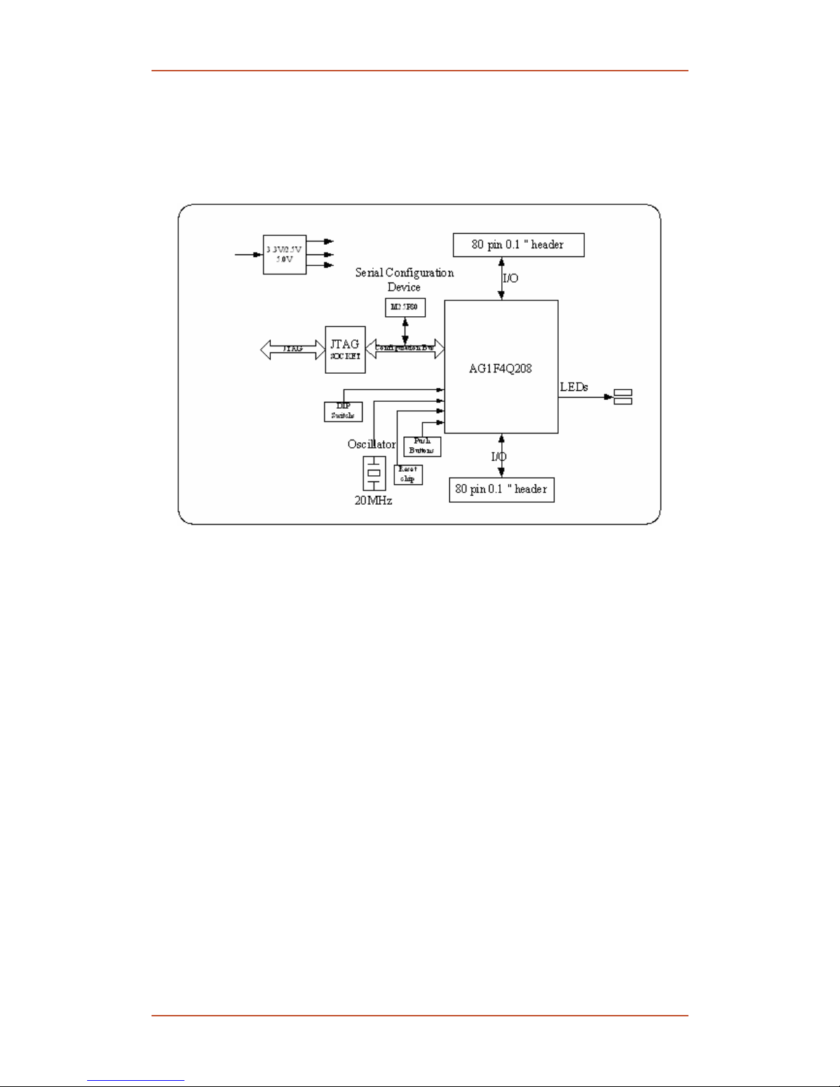
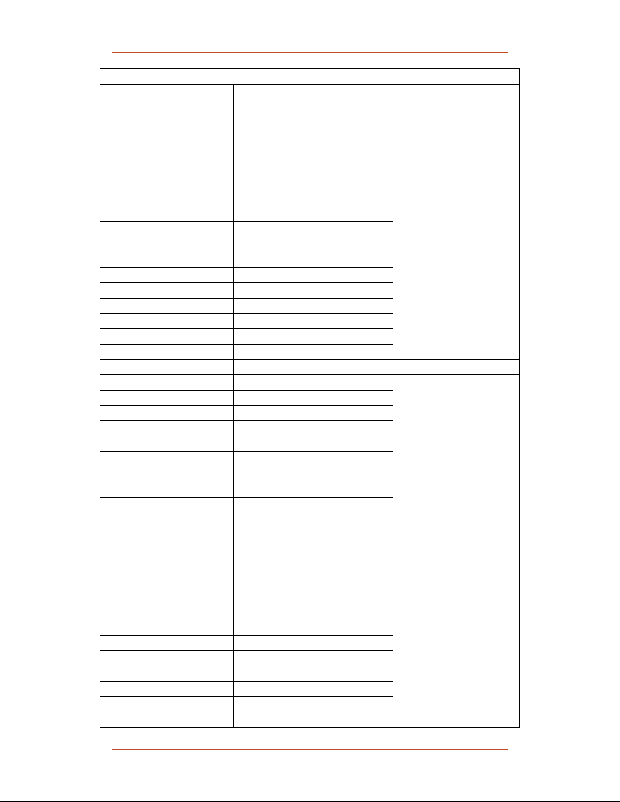
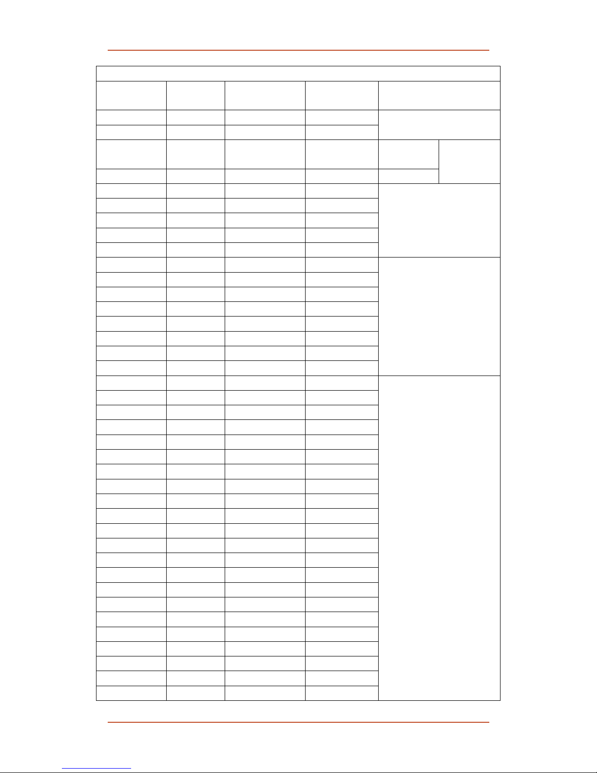
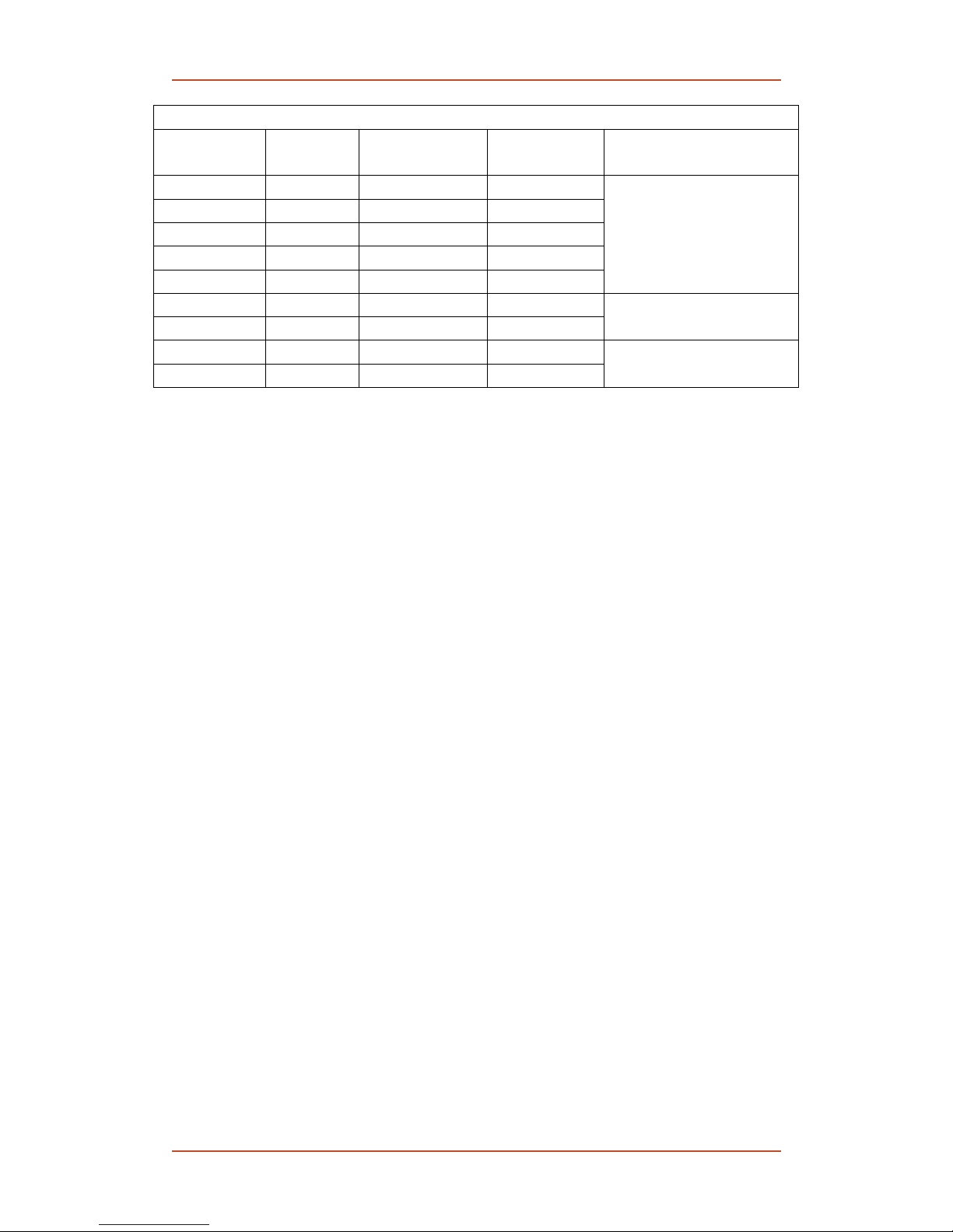
Table 1 Pin Assignment of the Connectors
AG1F4-BA Pin Signal Header on
RocKid-EB2-1F4C
Header on
RocKid-EB2-MA Description
IO91 RS232_TX1 J4-77 J9-77
IO92 RS232_RX1 J4-78 J9-78 RS-232
IO63 SCL J4-49 J9-49
I2C clock
signal
IO64 SDA J4-50 J9-50 I2C data signal
EEPROM
IO58 SPI_SCLK J4-44 J9-44
IO59 SPI_ADDR J4-45 J9-45
IO60 SPI_CS J4-46 J9-46
IO61 SPI_DOUT J4-47 J9-47
IO62 SPI_EOC J4-48 J9-48
SPI ADC
IO68 SW_DIP7 J4-54 J9-54
IO69 SW_DIP6 J4-55 J9-55
IO70 SW_DIP5 J4-56 J9-56
IO71 SW_DIP4 J4-57 J9-57
IO72 SW_DIP3 J4-58 J9-58
IO73 SW_DIP2 J4-59 J9-59
IO74 SW_DIP1 J4-60 J9-60
IO75 SW_DIP0 J4-61 J9-61
DIP switch S1
IO6 SRAM_A00 J3-16 J10-16
IO153 SRAM_A01 J3-17 J10-17
IO152 SRAM_A02 J3-18 J10-18
IO151 SRAM_A03 J3-19 J10-19
IO150 SRAM_A04 J3-20 J10-20
IO134 SRAM_A05 J3-43 J10-43
IO133 SRAM_A06 J3-44 J10-44
IO132 SRAM_A07 J3-45 J10-45
IO131 SRAM_A08 J3-46 J10-46
IO130 SRAM_A09 J3-47 J10-47
IO3 SRAM_A10 J3-37 J10-37
IO2 SRAM_A11 J3-36 J10-36
IO1 SRAM_A12 J3-35 J10-35
IO136 SRAM_A13 J3-34 J10-34
IO137 SRAM_A14 J3-33 J10-33
IO143 SRAM_A15 J3-27 J10-27
IO144 SRAM_A16 J3-26 J10-26
IO145 SRAM_A17 J3-25 J10-25
IO146 SRAM_A18 J3-24 J10-24
IO148 SRAM_DQ0 J3-22 J10-22
IO147 SRAM_DQ1 J3-23 J10-23
IO4 SRAM_DQ2 J3-38 J10-38
SRAM