decaWave TREK1000 User manual

© Decawave 2016 This document is confidential and contains information which is proprietary
to Decawave Limited. No reproduction is permitted without prior express written permission of
the author
TREK1000 User Manual
HOW TO INSTALL, CONFIGURE AND
EVALUATE THE DECAWAVE
TREK1000 TWO-WAY RANGING
(TWR) RTLS IC EVALUATION KIT
Version 1.08
This document is subject to change without
notice
TREK1000 User Manual
© Decawave 2016 This document is confidential and contains information which is proprietary to
Decawave Limited. No reproduction is permitted without prior express written permission of the
author
Page 2 of 54
DOCUMENT INFORMATION
Disclaimer
Decawave reserves the right to change product specifications without notice. As far as possible changes to
functionality and specifications will be issued in product specific errata sheets or in new versions of this
document. Customers are advised to check with Decawave for the most recent updates on this product.
Copyright © 2016 Decawave Ltd
LIFE SUPPORT POLICY
Decawave products are not authorized for use in safety-critical applications (such as life support) where a
failure of the Decawave product would reasonably be expected to cause severe personal injury or death.
Decawave customers using or selling Decawave products in such a manner do so entirely at their own risk
and agree to fully indemnify Decawave and its representatives against any damages arising out of the use of
Decawave products in such safety-critical applications.
Caution! ESD sensitive device. Precaution should be used when handling the device in order
to prevent permanent damage.
REGULATORY APPROVALS
This TREK1000 evaluation kit based on Decawave’s DW1000 IC is intended solely for use by
competent engineering personnel for the purposes of evaluating the use of Decawave’s DW1000
IC in wireless location and communications systems.
The TREK1000, as supplied from Decawave, has not been certified for use in any particular
geographic region by any regulatory body governing radio emissions in such regions.
The TREK1000 is supplied under the following conditions: -
The distribution and sale of the TREK1000 is intended solely for use in future development
of devices which may be subject to regulations or other authority governing radio emission.
This TREK1000 may not be resold by users for any purpose.
The TREK1000 as supplied by Decawave may not be incorporated directly into user
devices or products unless such products undergo the appropriate certification.
Operation of the TREK1000 in the development of future devices is at the discretion of the
user and the user bears all responsibility for any compliance with regulations laid down by
the authority governing radio emissions in the user’s jurisdiction.
All products developed by the user incorporating the DW1000 must be approved by the relevant
authority governing radio emissions in a jurisdiction prior to the marketing or sale of such products
in that jurisdiction. User bears all responsibility for obtaining such approval.
If the user has obtained the TREK1000 for any purpose other than those listed above the user
should return the TREK1000 to the supplier immediately.
FCC NOTICE: This kit is designed to allow (i) product developers to evaluate electronic
components, circuitry, or software associated with the kit to determine whether to incorporate such
items in a finished product and (ii) software developers to write software applications for use with
the end product. This kit is not a finished product and when assembled may not be resold or
otherwise marketed unless all required FCC equipment authorizations are first obtained. Operation
is subject to the conditions that this device not cause harmful interference to licensed radio stations
and that this device accept harmful interference. Unless the assembled kit is designed to operate
under Part 15, Part 18 or Part 95 of the FCC Rules, the operator of the kit must operate under the
authority of an FCC license holder or must secure an experimental authorization under Part 5 of the
FCC Rules.

TREK1000 User Manual
© Decawave 2016 This document is confidential and contains information which is proprietary to
Decawave Limited. No reproduction is permitted without prior express written permission of the
author
Page 3 of 54
TABLE OF CONTENTS
1INTRODUCTION..................................................................................................................... 7
1.1 RTLS .......................................................................................................................................... 7
1.2 DECAWAVE DW1000 IC ...............................................................................................................7
1.3 USE CASES &APPLICATIONS ...........................................................................................................8
1.4 MORE INFORMATION ....................................................................................................................8
2TREK1000 KIT CONTENTS....................................................................................................... 9
2.1 SUPPLIED IN THE TREK1000 BOX....................................................................................................9
2.2 AVAILABLE FROM THE DECAWAVE WEBSITE ......................................................................................9
2.3 TREK1000 SOURCE CODE ...........................................................................................................10
2.4 ITEMS NOT INCLUDED IN THE KIT ...................................................................................................11
2.5 THE EVB1000 UNIT ...................................................................................................................11
3TREK1000 HARDWARE PREPARATION AND SETUP................................................................ 13
3.1 CONNECT THE ANTENNA TO THE EVB1000 PCB .............................................................................13
3.2 MOUNTING OPTION FOR THE EVB1000 ANCHORS ..........................................................................13
3.3 POWERING THE EVB1000 ...........................................................................................................15
3.4 CONFIGURING THE EVB1000S......................................................................................................17
3.5 EVB1000 DISPLAY .....................................................................................................................18
4ARRANGEMENTS FOR DIFFERENT USE CASES ....................................................................... 20
4.1 TRACKING USE CASE....................................................................................................................20
4.1.1 Arrangement ...................................................................................................................21
4.2 GEO-FENCING USE CASE ..............................................................................................................21
4.2.1 Arrangement ...................................................................................................................22
4.3 NAVIGATION USE CASE ................................................................................................................23
5TREK1000 SOFTWARE PREPARATION AND SETUP................................................................. 25
5.1 INSTALL THE ST ARM USB DRIVER................................................................................................25
5.2 DOWNLOAD THE TREK1000 ZIP-FILE ............................................................................................25
5.3 PREPARE THE TREK1000 SOFTWARE.............................................................................................25
6THE USER INTERFACE........................................................................................................... 26
6.1 LAUNCH THE USER INTERFACE.......................................................................................................26
6.2 USER INTERFACE:STARTUP...........................................................................................................27
6.3 ANCHOR TABLE PANE ..................................................................................................................27
6.4 TAG TABLE PANE ........................................................................................................................28
6.5 SETTINGS PANE ..........................................................................................................................29
6.5.1 Configuration Tab............................................................................................................29
6.5.2 Floor Plan Tab..................................................................................................................33
6.5.3 Grid Tab...........................................................................................................................36
6.6 DISPLAY PANE ............................................................................................................................36
6.7 MINIMAP PANE ..........................................................................................................................37
6.8 MENU BAR ................................................................................................................................37
6.8.1 View Menu ......................................................................................................................38
6.8.2 Help Menu .......................................................................................................................38
7USAGE ................................................................................................................................ 39
7.1 NAVIGATION OR TRACKING USE CASES ...........................................................................................39
7.2 GEO-FENCING USE CASE ..............................................................................................................40

TREK1000 User Manual
© Decawave 2016 This document is confidential and contains information which is proprietary to
Decawave Limited. No reproduction is permitted without prior express written permission of the
author
Page 4 of 54
8ANALYSIS ............................................................................................................................ 42
8.1 LOG FILES ..................................................................................................................................42
8.1.1 Range Report Format ......................................................................................................42
8.2 Z-HEIGHT ..................................................................................................................................43
8.2.1 Adding a 4th Anchor (example only) ................................................................................44
9OTHER EVB1000 BOARD DETAILS ......................................................................................... 46
9.1 OFF-BOARD CONNECTOR HEADERS.................................................................................................46
9.1.1 J1 –SMA antenna connector...........................................................................................46
9.1.2 J4 –JTAG connector.........................................................................................................46
9.1.3 J5 –Micro USB connector................................................................................................46
9.1.4 J6 –External SPI connector..............................................................................................47
9.1.5 J7 –External DC supply....................................................................................................48
9.2 ON-BOARD SWITCH FUNCTIONS.....................................................................................................49
9.2.1 S1.....................................................................................................................................49
9.2.2 S2.....................................................................................................................................49
9.2.3 S3.....................................................................................................................................49
9.2.4 SW1 .................................................................................................................................50
9.3 ON-BOARD 2-PIN JUMPER FUNCTIONS............................................................................................50
9.4 ON-BOARD 3-PIN HEADERS WITH JUMPER FUNCTIONS.......................................................................50
9.4.1 J2 and J3 functions ..........................................................................................................50
9.4.2 J8 and J9 functions ..........................................................................................................51
10 REFERENCES .................................................................................................................... 52
10.1 LISTING..................................................................................................................................52
11 DOCUMENT HISTORY ....................................................................................................... 52
12 MAJOR CHANGES............................................................................................................. 52
13 FURTHER INFORMATION .................................................................................................. 54
LIST OF TABLES
TABLE 1: KIT CONTENTS –IN THE BOX ............................................................................................................9
TABLE 2: KIT CONTENTS –ON THE WEBSITE ..................................................................................................10
TABLE 3: TREK1000 SOURCE CODE PACKAGE...............................................................................................10
TABLE 4: KIT CONTENTS –ALSO REQUIRED OR USEFUL,NOT PROVIDED ............................................................11
TABLE 5: POWER OPTION SETTINGS .............................................................................................................15
TABLE 6: THE 4MODES OF TREK1000 ........................................................................................................17
TABLE 7: DIP SWITCH (S1) SETTINGS ON AN EVB1000 ..................................................................................18
TABLE 8: J1 PIN OUT ..................................................................................................................................46
TABLE 9: J4 PIN-OUT..................................................................................................................................46
TABLE 10: MICRO USB CONNECTOR PIN-OUT ................................................................................................46
TABLE 11: J6 PIN-OUT ...............................................................................................................................47
TABLE 12: J7 PIN-OUT................................................................................................................................48
TABLE 13:S2 SWITCH CONFIGURATION DESCRIPTIONS.....................................................................................49
TABLE 14: S3 SWITCH CONFIGURATION DESCRIPTIONS.....................................................................................49
TABLE 15: SW1 ARM RESET BUTTON ..........................................................................................................50
TABLE 16: J10 FUNCTION ...........................................................................................................................50
TABLE 17: J2 AND J3 FUNCTIONS .................................................................................................................50
TABLE 18: J8 AND J9 FUNCTIONS .................................................................................................................51

TREK1000 User Manual
© Decawave 2016 This document is confidential and contains information which is proprietary to
Decawave Limited. No reproduction is permitted without prior express written permission of the
author
Page 5 of 54
TABLE 19: TABLE OF REFERENCES................................................................................................................52
TABLE 20: DOCUMENT HISTORY ..................................................................................................................52
LIST OF FIGURES
FIGURE 1: TREK 1000.................................................................................................................................7
FIGURE 2: BACK AND FRONT VIEWS OF AN EVB1000 .....................................................................................12
FIGURE 3: CONNECT THE ANTENNA TO THE EVB1000 ....................................................................................13
FIGURE 4: EVB1000 MOUNTING OPTIONS USING THE STANDS........................................................................13
FIGURE 5: MOUNT EVB1000S ON TRIPODS ..................................................................................................14
FIGURE 6: DO NOT PLACE ANTENNAS TOO CLOSE TO THE WALL .......................................................................14
FIGURE 7: KEEP METAL OBJECTS BELOW THE ANTENNA...................................................................................15
FIGURE 8: EVB1000 POWER SUPPLY OPTIONS ...............................................................................................15
FIGURE 9: USB AND DC 3.6V TO 5.5V POWER SOURCE JUMPER CONNECTIONS ..................................................16
FIGURE 10: EVB1000 TREK CONFIGURATION DIP SWITCHES LOCATION........................................................... 17
FIGURE 11: EVB1000 TREK CONFIGURATION DIP SWITCHES (S1) FUNCTIONS..................................................17
FIGURE 12: EVB1000 DISPLAY STARTUP SCREEN...........................................................................................18
FIGURE 13: EVB1000 DISPLAY CONFIGURATION SCREEN ................................................................................18
FIGURE 14: EVB1000 DISPLAY RANGING SCREEN..........................................................................................19
FIGURE 15: TRACKING USE CASE:EXAMPLE ANCHOR SETTINGS ........................................................................20
FIGURE 16: TRACKING USE CASE:EXAMPLE TAG SETTINGS ..............................................................................20
FIGURE 17: TRACKING USE CASE:ARRANGEMENT ..........................................................................................21
FIGURE 18: GEO-FENCING USE CASE:EXAMPLE ANCHOR SETTINGS ..................................................................21
FIGURE 19: GEO-FENCING USE CASE:EXAMPLE TAG SETTINGS.........................................................................22
FIGURE 20: GEO-FENCING USE CASE:ARRANGEMENT ....................................................................................22
FIGURE 21: NAVIGATION USE CASE:EXAMPLE ANCHOR SETTINGS ....................................................................23
FIGURE 22: NAVIGATION USE CASE:EXAMPLE TAG SETTINGS...........................................................................23
FIGURE 23: NAVIGATION USE CASE:ARRANGEMENT ......................................................................................24
FIGURE 24: USER INTERFACE:STARTUP MESSAGE ..........................................................................................26
FIGURE 25: USER INTERFACE:STARTUP –ERROR MESSAGE .............................................................................26
FIGURE 26: USER INTERFACE:STARTUP VIEW ................................................................................................27
FIGURE 27: USER INTERFACE:ANCHOR TABLE PANE .......................................................................................28
FIGURE 28: USER INTERFACE:ANCHOR TABLE PANE .......................................................................................28
FIGURE 29: USER INTERFACE:TAG TABLE PANE –TRACKING/NAVIGATION MODE...............................................28
FIGURE 30: USER INTERFACE:TAG TABLE PANE –GEO-FENCING MODE ............................................................29
FIGURE 31: USER INTERFACE:SETTINGS PANE –CONFIGURATION TAB...............................................................31
FIGURE 32: USER INTERFACE:AUTO-POSITIONING .........................................................................................31
FIGURE 33: USER INTERFACE:FILTERING OPTIONS..........................................................................................32
FIGURE 34: USER INTERFACE:ENABLE LOCATION LOGGING..............................................................................32
FIGURE 35: USER INTERFACE:HIDE ANCHOR AND TAG TABLE PANES.................................................................33
FIGURE 36: USER INTERFACE:SHOW DISPLAY PANE ONLY ...............................................................................33
FIGURE 37: USER INTERFACE:SETTINGS PANE –FLOOR PLAN TAB ....................................................................34
FIGURE 38: USER INTERFACE:SETTINGS PANE –FLOOR PLAN TAB –CLEAR &SAVE SETTINGS...............................34
FIGURE 39: USER INTERFACE:POSITION FLOORPLAN.......................................................................................35
FIGURE 40: USER INTERFACE:MEASURE X-SCALE ON DISPLAY..........................................................................36
FIGURE 41: USER INTERFACE:SETTINGS PANE –GRID TAB...............................................................................36
FIGURE 42: USER INTERFACE:MINIMAP PANE ...............................................................................................37
FIGURE 43: USER INTERFACE:MENUS ..........................................................................................................37
FIGURE 44: USER INTERFACE:ABOUT US......................................................................................................38
FIGURE 45: READING THE LOG FILES.............................................................................................................43
FIGURE 46: TRILATERATION –2SOLUTIONS EXIST ..........................................................................................44

TREK1000 User Manual
© Decawave 2016 This document is confidential and contains information which is proprietary to
Decawave Limited. No reproduction is permitted without prior express written permission of the
author
Page 6 of 54
FIGURE 47: ADDING A 4TH ANCHOR ..............................................................................................................44
FIGURE 48: LOGICAL VIEW OF THE EVB1000.................................................................................................47

TREK1000 User Manual
© Decawave 2016 This document is confidential and contains information which is proprietary to
Decawave Limited. No reproduction is permitted without prior express written permission of the
author
Page 7 of 54
1 INTRODUCTION
The TREK1000 is an evaluation kit that allows the user to evaluate the DecaWave DW1000
IC in an RTLS environment in different use cases.
TREK stands for Two-Way Ranging (TWR) RTLS IC Evaluation Kit.
The Evaluation Kit enables the user to evaluate the performance of the IC in 3 different use
cases:
Tracking
Geo-Fencing
Navigation
Figure 1: TREK 1000
1.1 RTLS
Real-Time Location Systems (RTLS) are used across many industrial segments e.g. factory
automation, warehouse logistics, building automation, healthcare, sports.
Existing solutions (e.g. Wi-Fi, BLE, ZigBee) suffer from inaccurate location estimations, high
power consumption (short battery life) and costly installations & maintenance.
Decawave provides solutions to these issues by using UWB (Ultra-Wideband) technology in
a single IC. UWB-based RTLS use highly reliable time-based measurements to outperform
existing solutions in terms of accuracy, reliability and cost.
Decawave supplies key RTLS enabling blocks:
UWB IC for time-of-arrival (TOA) estimation
2D&3D location solver algorithm using Two-Way Ranging (TWR)
Source code examples for driving the ARM microprocessor and User Interface (UI)
used in TREK
1.2 Decawave DW1000 IC
The DW1000 is a fully integrated low power, single chip CMOS radio transceiver IC
compliant with the IEEE 802.15.4-2011 ultra-wideband (UWB) standard.
•It facilitates proximity detection (1-D) to an accuracy of +/- 10 cm using two-way
ranging time-of-flight (TOF) measurements.
•It facilitates real time location (2-D or 3-D) of assets to an accuracy of +/- 30 cm in
x and y (and z) using either two-way ranging (TOF) measurements or one-way
time difference of arrival (TDOA) schemes

TREK1000 User Manual
© Decawave 2016 This document is confidential and contains information which is proprietary to
Decawave Limited. No reproduction is permitted without prior express written permission of the
author
Page 8 of 54
•It spans 6 RF bands from 3.5 GHz to 6.5 GHz
•It supports data rates of 110 kbps, 850 kbps and 6.8 Mbps
•Its high data rates allow it to keep on-air time short thereby saving power and
extending battery lifetimes
•Its ability to deal with severe multipath environments makes it ideal for highly
reflective RF environments
The Decawave DW1000 is optimized for applications in Real Time Location Systems and
Wireless Sensor Networks across a variety of markets including agriculture, building control
and automation, factory automation, healthcare, safety & security, warehousing & logistics
and a range of others.
More information can be found in the DW1000 Data Sheet and User Manual.
1.3 Use Cases & Applications
The TREK1000 can be evaluated in 3 different use cases which are applicable to real-life
industrial and consumer applications.
1. Tracking Use Case: Determine location of the Tag relative to fixed Anchors.
Examples include asset-tracking (healthcare, farming, logistics), factory automation.
2. Geo-Fencing Use Case: Determine when Tags enter or leave a specific
perimeter/zone near an Anchor. Examples include location-based payments,
personal safety (forklifts, drilling machines), child-monitoring, “secure-my-valuables”
and security bubble applications.
3. Navigation Use Case: Track the 2D or 3D location of the Tag relative to fixed
Anchors. Examples include robotics and human navigation.
1.4 More Information
More information about the TREK1000 and the DW1000 IC can be found in the following
documentation and instructional videos:
TREK1000 Product Brief
TREK1000 Quick Start Guide
TREK1000 Source Code Guide: DecaRangeRTLS PC
TREK1000 Source Code Guide: DecaRangeRTLS ARM
Moving from TREK1000 to a Product
TREK1000 Setup and Installation Video
DW1000 Data Sheet
DW1000 User Manual
TREK1000 User Manual
© Decawave 2016 This document is confidential and contains information which is proprietary to
Decawave Limited. No reproduction is permitted without prior express written permission of the
author
Page 9 of 54
2 TREK1000 KIT CONTENTS
To use the TREK1000 the user needs the components of the kit box, software and
documentation from the Decawave website and a few other components that are not
provided for power-up and mounting.
These components are detailed below.
2.1 Supplied in the TREK1000 Box
The following items are delivered in the box when a TREK1000 kit is purchased.
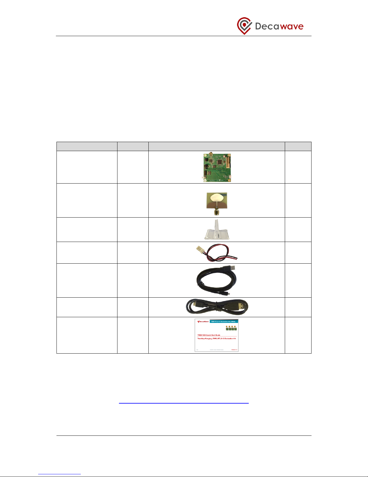
Table 1: Kit Contents –In the Box
Description
Quantity
Image
Check
EVB1000 PCB
4
UWB Antenna
4
EVB1000 Stands
4
DC Power Leads
4
1.8 m USB Cable
3
60 cm USB Cable
1
Quick Start Guide
1
2.2 Available from the Decawave Website
Supporting documentation, instructional videos, reference source code and the application
UI should be downloaded from the Decawave website. Go to this URL to download:
http://www.decawave.com/products/TREK1000
The downloaded zip-file contains the following items: -

TREK1000 User Manual
© Decawave 2016 This document is confidential and contains information which is proprietary to
Decawave Limited. No reproduction is permitted without prior express written permission of the
author
Page 10 of 54
Table 2: Kit Contents –On the Website
Item
Description
Type
Check
Documentation
TREK1000 Quick Start Guide
Quick Setup Instructions
pdf
TREK1000 User Manual
Detailed description of setup,
installation and usage including User
Interface description
pdf
Moving from TREK1000 to a Product
Guidance on how to proceed from
evaluation to product design
pdf
TREK1000 Expansion Options
Options for mixing TREK1000 and
TREK1000 hardware to expand the
system
pdf
PC Application
DecaRangeRTLS PC
PC Application executable
exe
2.3 TREK1000 Source Code
TREK purchasers can get access to the ARM microcontroller source code, the PC
application source code and source code documentation.
If you are interested in accessing this source code and documentation then you should login
to the Decawave website (www.decawave.com) and proceed to the TREK1000 registration
page at http://www.decawave.com/trekreg. If you attempt to access this registration page
before you are logged in you will be redirected to the login page. Once on the registration
page, you will be asked to enter the serial number of your TREK1000 which can be found on
the outside of the box. Once the serial number has been verified you will be automatically
redirected to the TREK source code download page. Clicking on the download will launch a
disclaimer notice, which you will be asked to accept by ticking a box after which the
download of the source code package will commence.
The downloaded zip-file contains the following items: -
Table 3: TREK1000 Source Code Package
Item
Description
Type
Documentation
TREK1000 Source Code Guide:
DecaRangeRTLS PC
PC Application source code description
pdf
TREK1000 Source Code Guide:
DecaRangeRTLS ARM
ARM firmware source code description
pdf
Firmware
DecaRangeRTLS ARM
ARM firmware binary
bin
Software
DecaRangeRTLS PC
PC Application source code
zip
DecaRangeRTLS ARM
ARM firmware source code
zip

TREK1000 User Manual
© Decawave 2016 This document is confidential and contains information which is proprietary to
Decawave Limited. No reproduction is permitted without prior express written permission of the
author
Page 11 of 54
2.4 Items Not Included in the Kit
There are other items which may be used to install and use the TREK1000. Some are
required and some are useful.
These are listed in the table below.
Table 4: Kit Contents –Also Required or Useful, Not Provided
Description
Quantity
Image
Required?
PC
1
OS should be Windows 7 or 8
Required
STM32 Virtual COM
Port Driver
1
STSW-STM32102
http://www.st.com/web/en/catalog/tools/
PF257938
Required
Tripods
3-4
Useful
SMA Torque Wrench
1
Recommended
Options for Powering EVB1000 Units
USB Battery
3
OR
PC Connections
3
OR
Mobile Battery
3
OR
USB->Power
Adaptor
3
2.5 The EVB1000 Unit
The image below shows the key features of an EVB1000 unit.

TREK1000 User Manual
© Decawave 2016 This document is confidential and contains information which is proprietary to
Decawave Limited. No reproduction is permitted without prior express written permission of the
author
Page 12 of 54
Figure 2: Back and Front Views of an EVB1000

TREK1000 User Manual
© Decawave 2016 This document is confidential and contains information which is proprietary to
Decawave Limited. No reproduction is permitted without prior express written permission of the
author
Page 13 of 54
3 TREK1000 HARDWARE PREPARATION AND SETUP
This section details the steps necessary to prepare the TREK1000 hardware for use.
3.1 Connect the Antenna to the EVB1000 PCB
The 4 EVB1000 PCBs come with 4 UWB (Ultra-Wideband) antennas. Each antenna must be
screwed on to the EVB1000 using the SMA connector.
It is recommended that an SMA torque wrench is used to tighten the antenna to the
EVB1000.
Note that poor connections can result in under performance in the system.
Figure 3: Connect the Antenna to the EVB1000
3.2 Mounting Option for the EVB1000 Anchors
Depending on the use case that is being evaluated, 1 or more of the EVB1000 units will be
mounted.
Figure 4: EVB1000 Mounting Options Using the Stands

TREK1000 User Manual
© Decawave 2016 This document is confidential and contains information which is proprietary to
Decawave Limited. No reproduction is permitted without prior express written permission of the
author
Page 14 of 54
The figure above shows the EVB1000 sitting in the stands that are provided in the box.
The stands could be attached to a tripod, an office partition or any other flat surface for the
stand to sit on.
It is recommended that the stand be firmly clamped into place or fixed using tape or Velcro
tape to ensure the units do not move during testing.
Figure 5: Mount EVB1000s on Tripods
When mounting the EVB1000 units do not place the antennas too close to walls or any
other objects as this can interfere with the radiation pattern of the antennas. It is
recommended that the antenna be greater than 15 cm away from the nearest object.
Figure 6: Do Not Place Antennas too Close to the Wall
TREK1000 User Manual
© Decawave 2016 This document is confidential and contains information which is proprietary to
Decawave Limited. No reproduction is permitted without prior express written permission of the
author
Page 15 of 54
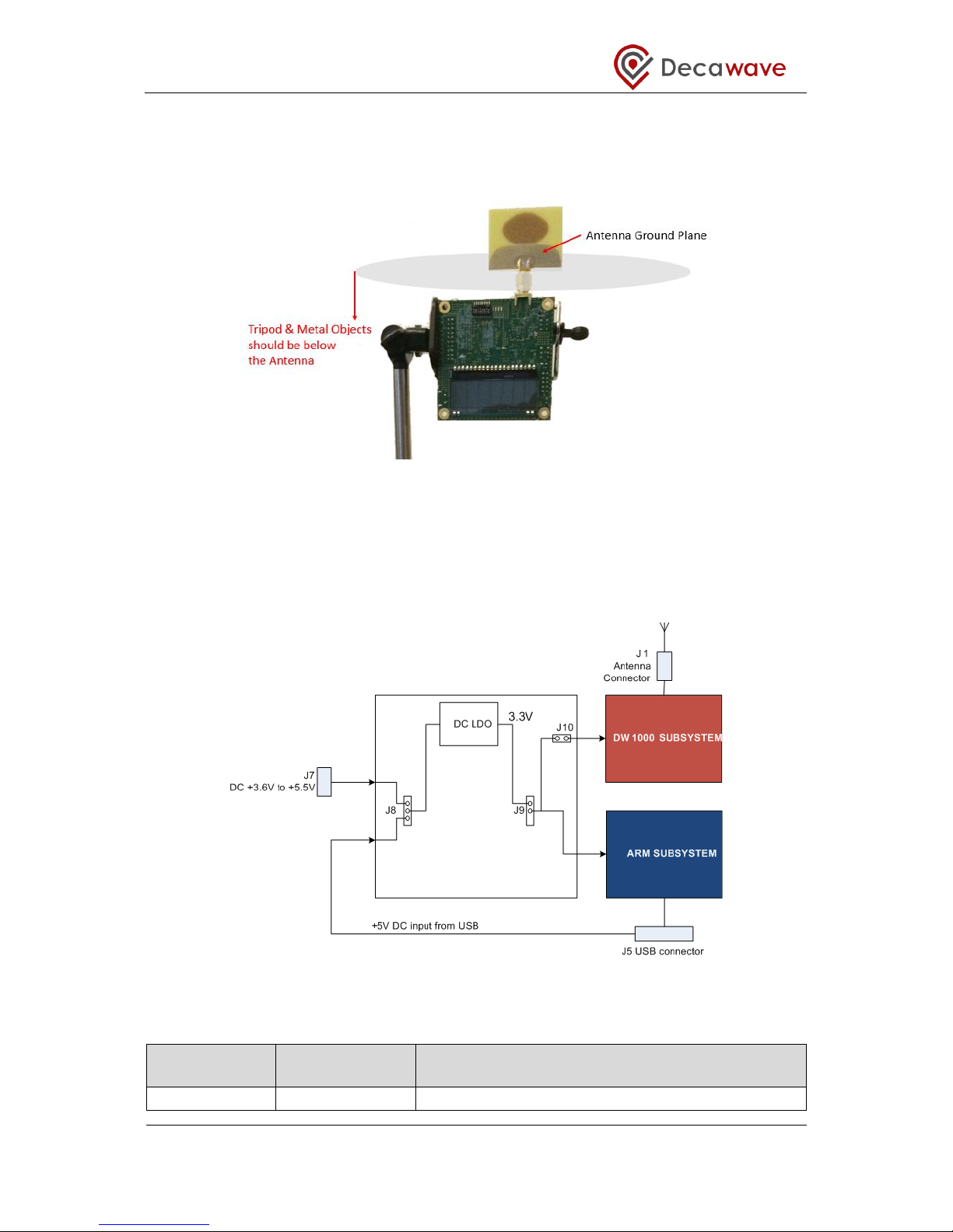
When mounting the EVB1000 units on metal tripods or poles ensure that the top of the poles
are below the ground plane of the antennas. The ground plane of the antenna is considered
to be the top of the SMA connector under the antenna.
Figure 7: Keep Metal Objects below the Antenna
3.3 Powering the EVB1000
The EVB1000 can be powered either via an external DC power supply (or battery) through
jumper J7 on the back of the EVB1000 using the supplied power cable leads or via a
standard 5 V 500 mA USB power supply through jumper J5. To change between the two,
jumper J8 is used as shown in the figure below.
Figure 8: EVB1000 power supply options
Table 5: Power Option Settings
Power Source
J8
(Insert on pins)
Comment
USB
2 & 3
The USB port to which you connect the EVB1000 should

TREK1000 User Manual
© Decawave 2016 This document is confidential and contains information which is proprietary to
Decawave Limited. No reproduction is permitted without prior express written permission of the
author
Page 16 of 54
Power Source
J8
(Insert on pins)
Comment
be capable of supplying at least 250 mA
3.6 V to 5.5 V
1 & 2
In this mode the externally applied supply is indirectly
connected to the on-board circuitry through an LDO
regulator
Changes to jumper settings should only be made with the board powered down –
under no circumstances should jumper settings be changed while power is applied to
the board via any of the possible off-board connectors, or damage to the board may
result.
For the two power source options the positions of the jumpers are shown in Figure 9.
Jumpers J2 and J3 can be used to select whether sections of DW1000 are powered with 1.8
V or 3.3 V, for more details on this operation see Reference [1].
Figure 9: USB and DC 3.6V to 5.5V power source jumper connections

TREK1000 User Manual
© Decawave 2016 This document is confidential and contains information which is proprietary to
Decawave Limited. No reproduction is permitted without prior express written permission of the
author
Page 17 of 54
3.4 Configuring the EVB1000s
In the TREK1000 system there are 4 modes that can be evaluated:
Table 6: The 4 Modes of TREK1000
Mode
Mode
Description
Data
Rate
Channel
Location
Rate
PRF
Preamble
Length
Preamble
Code
L2
‘Long’ range
/ Chan. 2
110 kbps
2: 3.993 GHz
3.57 Hz
16 MHz
1024
4
L5
‘Long’ range
/ Chan. 5
110 kbps
5: 6.489 GHz
3.57 Hz
16 MHz
1024
3
S2
‘Short’ frame
/ Chan. 2
6.8 Mbps
2: 3.993 GHz
10 Hz
16 MHz
128
4
S5
‘Short’ frame
/ Chan. 5
6.8 Mbps
5: 6.489 GHz
10 Hz
16 MHz
128
3
Also, each EVB1000 unit can be configured as either an Anchor or a Tag.
The configuration for each unit is set using the TREK configuration DIP switches (S1) on the
PCB.
Figure 10: EVB1000 TREK Configuration DIP Switches Location
Figure 11: EVB1000 TREK Configuration DIP Switches (S1) Functions
TREK1000 User Manual
© Decawave 2016 This document is confidential and contains information which is proprietary to
Decawave Limited. No reproduction is permitted without prior express written permission of the
author
Page 18 of 54
The DIP switch settings are described in the table below.
Table 7: DIP Switch (S1) Settings on an EVB1000
Switch
Function
Function
1
Reserved
This switch should be set to ON
2
MODE
ON: Data Rate = 6.8 Mbps
OFF: Data Rate = 110 kbps
3
CHANNEL
ON: Channel 5
OFF: Channel 2
4
UNIT
ON: Anchor
OFF: Tag
5
UNIT ID [2]
Set the ID numbers of the EVB1000 units.
Switch 7 is the LSB.
ID=1 => UNIT ID[2:0] = 001
6
UNIT ID [1]
7
UNIT ID [0]
8
Reserved
This switch should be set to OFF
The TREK configuration DIP Switches can be found on the front of the EVB1000 unit above
the display.
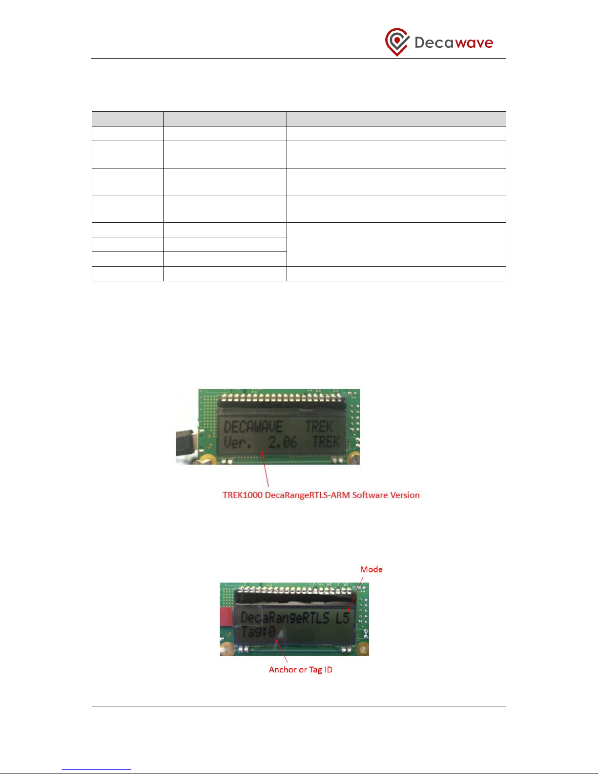
3.5 EVB1000 Display
When the EVB1000 is powered up there is a start-up screen appears containing the version
of DecaRangeRTLS ARM software that is running on the microprocessor.
Figure 12: EVB1000 Display Startup Screen
After about 20 s the display changes to show the current operating mode and the
configuration as Anchor or Tag.
Figure 13: EVB1000 Display Configuration Screen
TREK1000 User Manual
© Decawave 2016 This document is confidential and contains information which is proprietary to
Decawave Limited. No reproduction is permitted without prior express written permission of the
author
Page 19 of 54
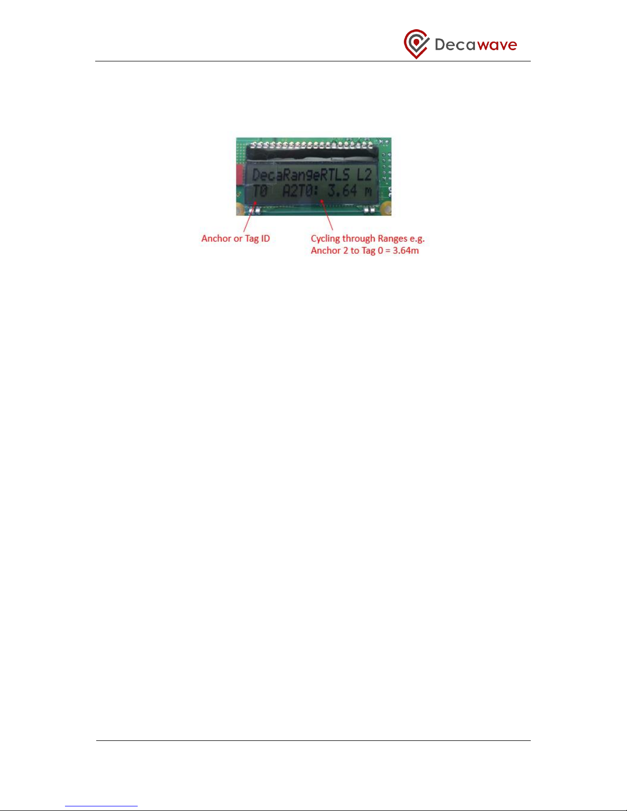
Once the Tag and Anchors start communicating (two-way ranging) the Anchor-to-Tag
measured distances appears on the display. The display will cycle through the distances
from the unit with the display to the other units.
Figure 14: EVB1000 Display Ranging Screen

TREK1000 User Manual
© Decawave 2016 This document is confidential and contains information which is proprietary to
Decawave Limited. No reproduction is permitted without prior express written permission of the
author
Page 20 of 54
4 ARRANGEMENTS FOR DIFFERENT USE CASES
This section shows the arrangement of the EVB1000 units when evaluating the 3 different
topologies:
1. Tracking Use Case
2. Geo-Fencing Use Case
3. Navigation Use Case
4.1 Tracking Use Case
For evaluating the tracking use case the system is configured as:
3 Anchors
1 Tag
In this case example below: Channel 2, 110 kbps is selected as the operating mode.
The 3 Anchors are configured as shown below.
Figure 15: Tracking Use Case: Example Anchor Settings
The Tag is configured as shown below.
Figure 16: Tracking Use Case: Example Tag Settings
Table of contents
Other decaWave Motherboard manuals


