AGP DEP25 User manual
1
For your personal safety,
READ and UNDERSTAND before using.
SAVE THESE INSTRUCTIONS FOR FUTURE REFERENCE.
Version:20160811
2
FUNCTIONAL DESCRIPTION
1
2
3
45
6
7
8
9
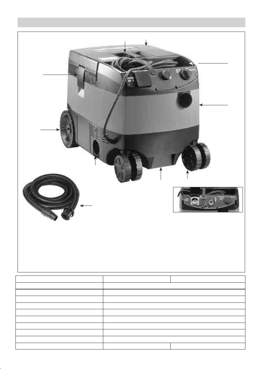
1. Tank Cover Latch
2. Rear Wheels (With Brakes)
3. Exhaust/Blower Port
4. Front Lower Hand Grip
5. Castor Wheels
6. Hose Port
7. Power Cable Storage
8. Tank Cover
9. Top Handle
10. Vacuum Cleaner
Hose- With Rubber Power
Tool Connector FIG.1
10
Pneumatic Switching Model
(Optional)
Model Pneumatic Switching Version
Power Input 1200W
Voltage See machine nameplate
Max. Airflow 4000 l/min (141.3 CFM)
Max. Suction (lift) 25 kpa (250 mbar, 100.4 inches of water)
Protection IP 44
Max. Dust Capacity 25 L (6.6 gallons)
Max. Connected Power Tool 2200 W
Soft Start With
Dimensions (LxWxH) 598mm x 408mm x 420mm
Net Weight 12.9kg (28.44 Lbs) 13.8kg (30.42 Lbs)

3
SAFETY INSTRUCTIONS
READ ALL INSTRUCTIONS BEFORE USING THIS DEVICE.
To reduce the risk of fire, electric shock, or injury:
1. Do not leave this device unattended when plugged in. Unplug when not in use and before servicing.
2. To reduce the risk of electric shock. Do not expose to rain or immerse in water. Store indoors.
3. Do not allow to be used as a toy. Careful attention is necessary when used by or near children or animals.
4. Use only as described in this manual. Use only manufacturer recommended attachments.
5. Do not use with a damaged power supply cord or plug. If the device is not working properly, has been
dropped, damaged, left outdoors, or immersed in or dropped into water, bring it to a service center.
6. Do not pull or carry by the power supply cord, use the power supply cord as a handle, close a door on
power cord, or pull power cord around sharp edges or comers. Keep power cord away from heated
surfaces.
7. Do not unplug by pulling on power cord. To unplug, grab the plug, not the cord.
8. Do not handle plug or appliance with wet hands.
9. Do not use the device with any opening blocked; keep openings free of solid objects or anything that will
impede airflow.
10. Keep hair, loose clothing, fingers, and all parts of body away from openings and moving parts.
11. Turn off switch before unplugging.
12. Use extra care when operating on stairs.
13. Do not use this machine to vacuum flammable liquids, or vacuum in areas where these may be present.
14. Connect to a properly grounded outlet only. See Grounding Instructions.
15. Do not vacuum anything that is burning or smoking, such as cigarettes, matches, or hot ashes. Do not use
this device to extract flammable or explosive dusts (such as magnesium, aluminum, etc.). Risk of
explosion!
16. Do not use without dust bag and/or filters in place.
17. Do not use to vacuum up caustic or corrosive liquids (e.g. acids, alkalis, solvents).
18. Protect the power cord against heat, oil and sharp edges.
19. Check the plug and power cord regularly and have them replaced by a qualified technician if damaged.
20. Use only approved accessories.
GROUNDING INSTRUCTIONS
a. This machine is not intended for use by persons (including children) with reduced physical, sensory or
mental capabilities, or lack of experience and knowledge.
b. If the supply cord is damaged, it must be replaced by the manufacturer, its service agent or similarly
qualified persons in order to avoid a hazard.
c. This machine is intended for commercial use, for example in hotels, schools, hospitals, factories, shops,
offices and rental businesses.

4
WARNING : Operators shall be adequately instructed on the use of these machines.
WARNING : This machine is not suitable for picking up hazardous dust.
WARNING : Only use the socket outlet on the machine for purpose specified in the instructions.
WARNING : If foam or liquid escapes from the machine, switch off immediately.
This appliance must be grounded. If it should malfunction or break down while in use, grounding provides a
path of least resistance for the electric current and reduces the risk of electric shock to the operator. This
appliance has a power cord with equipment-grounding conductor and grounding plug. The plug must be
inserted into an appropriate outlet that is properly installed and grounded in accordance with all local codes
and ordinances.
Improper connection of the equipment-grounding conductor can result in a risk of electric shock. Check with a
qualified electrician or service person if you are in doubt as to whether the outlet is properly grounded.
Do not modify the plug provided with the machine. If it will not fit the outlet, have a proper outlet installed by
a qualified electrician.
Various dust created by power sanding, sawing, grinding, drilling and other construction activities contains
chemicals known to cause cancer, birth defects or other reproductive harm. Some examples of these chemicals
are:
Lead from lead-based paints, crystalline silica from bricks and cement and other masonry products, and
arsenic and chromium from chemically-treated lumber. The risk from these exposures varies, depending on
how often you do this type of work.
To reduce your exposure to these chemicals: work in a well ventilated area, and work with approved safety
equipment, such as dust masks that are specially designed to filter out microscopic particles.
Symbols used in this manual
V…….......volts
A…….......amperes
Hz……......hertz
W……......watt
~………....alternating current
n
0
………..no load speed
min-1….....revolutions or reciprocation
per minute
......warning of general danger
.….class II tool
.…with electrical earth
.......read these instructions
......always wear eye protection
......always wear a dust mask.
.....always wear hearing protection
.....wear safety-approved hard hat
do not dispose of electric tools,
accessories and packaging together
with household waste material
5
Intended use
This vacuum cleaner is primarily designed to operate in conjunction with power tools which require dust
extraction, such as sanders, saws, wall chasers, scouring machines, etc. This machine extracts non-dangerous
dusts, dirt, shavings etc.
This machine may also be used to vacuum water and other non-flammable and non corrosive liquids.
The end user/operator is solely responsible for any damage or accident should the machine be used for any
use other than its intended purpose.
Preparation and initial operation
Electrical connection
The operating voltage shown on the rating plate must correspond to the voltage of the power supply. Make
sure that the vacuum cleaner is switched off when you plug the power supply cable into the socket.
CAUTION!
This machine must ALWAYS be plugged into a properly grounded outlet. NEVER operate the machine if
it is not grounded. This will result in a static electrical build-up which will destroy the machine's
electronic components.
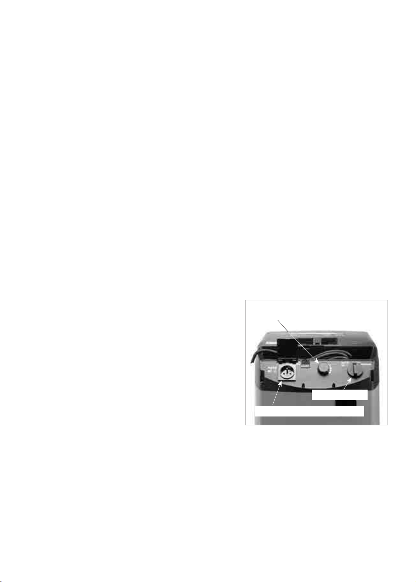
On/Off Switch Modes (see FIG.2)
This machine has a multi-mode On/Off Switch.
In position “OFF” the vacuum cleaner is switched off but there is
always current to the Integrated Switching Appliance Socket.
Different modes of operation are possible:
Switch position “MANUAL”:
The cleaner motor starts immediately and runs continuously.
Switch position“AUTO –AC”:
The Integrated Switching Appliance Socket is live. The cleaner
motor starts only when the tool connected to the appliance
socket is switched on. There is a 1 second delay in the vacuum
starting (to avoid tripping the circuit breaker) and a 10 second
delay in shutting off (to clear the hose of dust) followed by a cycle of the filter shaker.
Before turning the switch to the“AUTO –AC” position, ensure that the tool connected to the appliance socket is
switched off.
Observe the maximum connected load of 2200W for the Integrated Switching Appliance Socket.
Switch position“AUTO –AIR”(Optional Pneumatic Switching equipped models only):
In this mode, the machine starts only when the air tool connected in series with the Pneumatic Integrated
Switching Connector is switched on. Note that if the switch is in this positon and there is no air supply
connected then the machine will run continuously like the "Manual" switch position.
FIG.2
Integrated Switching Socket
Suction Power Control Wheel
On/Off Switch

6
Automatic Filter Shaker Function
This machine is equipped with an automatic electromagnetic filter shaker device. It operates automatically
with a cycle every 20 seconds to shake accumulated dust from the Diaphragm Filter. It will also cycle when the
switch is switched off (both in manual and automatic modes) It is fully automatic and only operates when the
Diaphragm Filter is in place. When it engages, there will be a slight noise. This noise is normal and does not
indicate any malfunction of the machine. To minimize noise, always install the Diaphragm Filter with the
exposed metal side of the anvil facing downwards.
Suction Power Control (see FIG.2)
The Suction Power Control Wheel can be used to adjust the suction to suit the situation. In some cases, less
than full power will be needed. For example, with small sanders, too much suction power will tend to make the
sander “stick” to the workpiece. In that case, the suction power needs to be turned down. Lowering the suction
power will also have the side benefit of making less noise.
Special instructions for (Optional)Pneumatic Switching Models:
These pneumatic models are equipped with an air coupling and
an air nipple for connecting the machine in-line with one's
compressed-air tool. Then the integrated switching will be
triggered by the air tool. See FIG.3
Connecting a compressed-air tool (Optional Pneumatic Switching Models only)
Connect the air supply to the side marked "Line" and the tool to the side marked "Tool".
When the compressed-air module is fitted, the automatic cut-in also operates in conjunction with pneumatic
tools.
For the length of air hose which is connected from air compressor to vacuum cleaner, we recommend to use at
least 12M. For the length of air hose which is connected from pneumatic tool to vacuum cleaner, we
recommend to use below 4M ( including 4M). Otherwise, the function of "AUTO-AIR " could be not working, or
vacuum cleaner could be not stopped when pneumatic tool is switched off.
We also recommend using an air pressure regulator/oiler.
Make sure that the compressed- air tool is switched off when plugging it in and unplugging it!
FIG.3
Air Nipple Air Coupling
7
Application
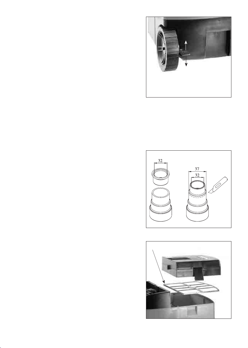
The 2 rear wheels may be locked by the brakes, which will
prevent the machine from rolling away unexpectedly. To lock,
either raise or lower the brake levers. To unlock, move the brake
levers to the center position. See FIG.4
The Electric Blower function
The hose may be connected to the Exhaust Port for powerful blower function. The blower is very useful for a
variety of purposes such as drying and cleaning.
The 32mm/37mm Rubber Power Tool Connector
This connector is designed to connect to the dust extraction
port of a power tool. Directly connect to the port if it is 32mm.
Carefully slice off one section for 37mm ports. Note-Remember
to save the sliced off segment, since it may be reversed and
reinserted into the connector to sleeve it back down to 32mm.
See fig.5
Machine Set up: Filter Configurations:
Removing and Mounting the Diaphragm Filter
(see FIG. 6)
Whether wet or dry vacuuming, The diaphragm filter should
always be used.
It is washable and incorporates the Automatic Filter Shaker. To
remove or replace:
• Ensure that the machine is unplugged.
• Open the unit by opening the 2 catches located on the
sides of the machine.
• Lift away the Tank Cover
• Remove the Diaphragm Filter
FIG.4
Brake Lever: Center Position Is "Off",
Either Up Or Down Positions Are "On"
FIG.5
FIG.6
Diaphragm Filter
8
• When replacing the Diaphragm Filter, ensure that it seats properly in the channel at the top rim of the
tank so that it makes a good seal.
• The exposed metal part of the anvil should be facing down.
• Replace the Tank Cover and 2 catches.
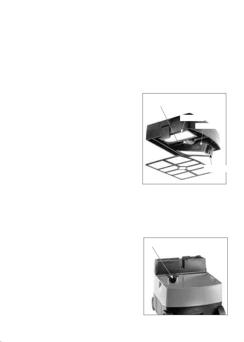
Removing and Mounting the pair of Main Filters (see FIG. 7)
The pleated Main Filters are the standard second stage filters. (The optional special Wet-Use Main Filters are
also removed and mounted in the same way as the standard pleated Main Filters).
To remove or replace:
• Ensure that the machine is unplugged.
• Open the unit by opening the 2 catches located on the
sides of the machine.
• Lift away the Tank Cover
• Looking at the underside of the Tank Cover, push the
catch of one of the Filter Frames. The Filter Frame will
come away from the Tank Cover.
• The Main Filter may now be removed.
• To replace, first place the Main Filter in the Filter Frame.
Then engage the tangs of the Filter Frame on one end and
snap in place on the other end. When replacing, ensure
that they are seated properly to make a good seal.
• Replace the Tank Cover and 2 catches.
NOTE: If dust is blowing out of the exhaust port, this indicates that at least one of the main filters either
has a hole, or is not seated properly.
Mounting Filter Bags (see FIG. 8)
Except when wet vacuuming, the filter bag must always be
mounted.
• Ensure that the machine is unplugged.
• Open the unit by opening the 2 catches located on the
sides of the machine.
• Lift away the Tank Cover
• Remove the Diaphragm Filter
• Do not leave the bag fully flat and folded. Help the bag to
open somewhat by hand so that it will be able to open
properly when the machine starts.
• Fully attach the bag opening onto the connection port.
• Replace the Diaphragm Filter (Recommended).
• Replace the Tank Cover and 2 catches.
FIG.7
Main Filter
Electromagnetic Filter
Shaker
Catch
Filter Frame
FIG.8
Filter Bag Connection Port

9
Vacuuming dry media
WARNING! Not suitable to vacuum hazardous or toxic substances such as asbestos. The filters may not
be able to capture all particles and may exhaust them back into the environment!
Before using the vacuum cleaner to extract dry materials, the machine must set up in a dry vacuuming
configuration. The pair of Main Pleated Filters must always be in place. The Filter bag and Diaphragm Filters
must both be mounted at all times.
NOTE: It is not recommended to dry vacuum when there is liquid in the tank or if the tank and filters are
still wet. Severe caking of dust and possible damage will occur.
Whenever transitioning from wet to dry vacuuming, ensure the entire tank and filter system is clean and
dry. If it is necessary to transition often between dry and wet vacuuming, it is best to have 2 sets of first
stage and main filters.
Vacuuming liquids
WARNING! Never attempt to vacuum flammable or corrosive liquids!
CAUTION: Never begin wet vacuuming when there is dry dust in the tank. Severe caking of dust and
possible damage to the machine may occur. Always clean the tank before beginning.
A paper disposable filter bag may not be used when vacuuming liquids. Use the washable Diaphragm Filter or
a washable filter bag for the first stage and the pair of special Wet-Use Main Filters.
When full, empty the tank by opening the tank cover and carefully dumping out.
The Automatic Liquid Overflow Switch (see FIG. 9)
When the maximum liquid level is reached, a shut-off switch
automatically shuts off the motor. To function properly, the
automatic overflow switch must be kept clean. When preparing
to vacuum liquids, clean the electrodes before beginning.
NOTE: The automatic overflow switch only functions with
electrically conductive liquids, such as water. It will not
function with non-conductive liquids, such as oils. When
vacuuming these, check the level regularly.
Maintenance and care
Always unplug power supply cord from the socket before carrying out any maintenance work!
Any maintenance and repair work requiring an opening of the motor housing may only be carried out by an
authorized service center.
FIG.9
Overflow Switch Electrodes Must Be
Kept Clean

10
Clean the filters as needed
If the suction power noticeably diminishes, this indicates that the filtering system may be becoming clogged
with fine particles.
1. If a paper dust bag is used, replace it. If a washable bag is used, empty it and wash it with water. Allow it
to dry fully if vacuuming dry media.
2. If the Diaphragm Filter needs to be cleaned, simply remove it and either vacuum it or wash it with water.
Allow it to dry fully if vacuuming dry media.
3. Remove the pleated main filters and make every effort to shake them out. If they are severely clogged,
replace them.
At least yearly, a safety test should be made to check for any possible damage to the filter or leaks in the
machine’s filtering system.
ELECTRONICS BOARD LED CODES AND ERROR CODES
The electronics board is designed to flash certain codes which show its mode of operation whenever it is
plugged in. This is not normally visible to the operator, since the electronics board is located inside the casing
of the machine. But if the machine is disassembled during service the electronic board’s LED lamp will be
visible. Most of the codes are just indicating normal operation. Only the motor open circuit/short circuit is an
error code. Below are the meanings of the codes:
MANUAL LED flashes 0.2 seconds on,
then 0.7 seconds off.
LED flashes 0.2 seconds on,
OFF then 0.2 seconds off, x 2 times,
then off 0.5 seconds. Cycle repeats. (normal)
LED flashes 0.2 seconds on,
AUTO AC then 0.2 seconds off, x 3 times, This indicates normal operation.
then off 0.5 seconds. Cycle repeats.
AUTO AIR LED flashes 0.2 seconds on,
(for pneumatic switching models only) then 0.2 seconds off, x 4 times, This indicates normal operation.
then off 0.5 seconds. Cycle repeats.
Automatic Liquid Overflow Switch, LED flashes 0.5 seconds on, This indicates normal operation of the overflow
indicating tank is full then 0.5 seconds off. Cycle repeats. switch when the tank is full of liquid.
Error code If the motor is either short circuited or is an open circuit,
the LED flashes 1 second on, then 1 second off. Cycle repeats.
If the replacement of the power supply cord is necessary, this has to be done by the manufacturer or
their agent in order to avoid a safety hazard.
WARNING: All repairs must be entrusted to an authorized service center. Incorrectly performed repairs
could lead to injury or death.
11
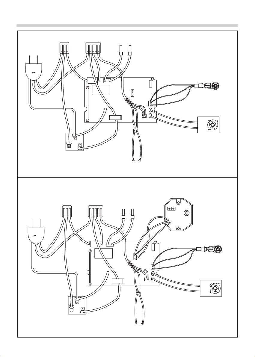
WIRING
YELLOW
WHITE
WHITE
RED
YELLOW
EMC
WHITE
BLACK
RED
YELLOW
Main Switch
3 - Position
Liquid Overow Switch
Integrated Switch
Appliance Socket
Heat
Sink
GREEN
GREEN
Earth
AC
BROWN
BLUE
BLUE
WHITE
Filter Shaker
Electronics
Board
Suction Power Control
YELLOW
WHITE
WHITE
RED
YELLOW
EMC
WHITE
BLACK
RED
YELLOW
Main Switch
3 - Position
Liquid Overow Switch
Integrated Switch
Appliance Socket
Heat
Sink
GREEN
GREEN
Earth
AC
BROWN
BLUE
BLUE
WHITE
Filter Shaker
Electronics
Board
Suction Power Control
Integrated Switching Unit
WHITE
RED BLACK
Pneumatic Switching Model
YELLOW
WHITE
WHITE
RED
YELLOW
EMC
WHITE
BLACK
RED
YELLOW
Main Switch
3 - Position
Liquid Overow Switch
Integrated Switch
Appliance Socket
Heat
Sink
GREEN
GREEN
Earth
AC
BROWN
BLUE
BLUE
WHITE
Filter Shaker
Electronics
Board
Suction Power Control
YELLOW
WHITE
WHITE
RED
YELLOW
EMC
WHITE
BLACK
RED
YELLOW
Main Switch
3 - Position
Liquid Overow Switch
Integrated Switch
Appliance Socket
Heat
Sink
GREEN
GREEN
Earth
AC
BROWN
BLUE
BLUE
WHITE
Filter Shaker
Electronics
Board
Suction Power Control
Integrated Switching Unit
WHITE
RED BLACK
12
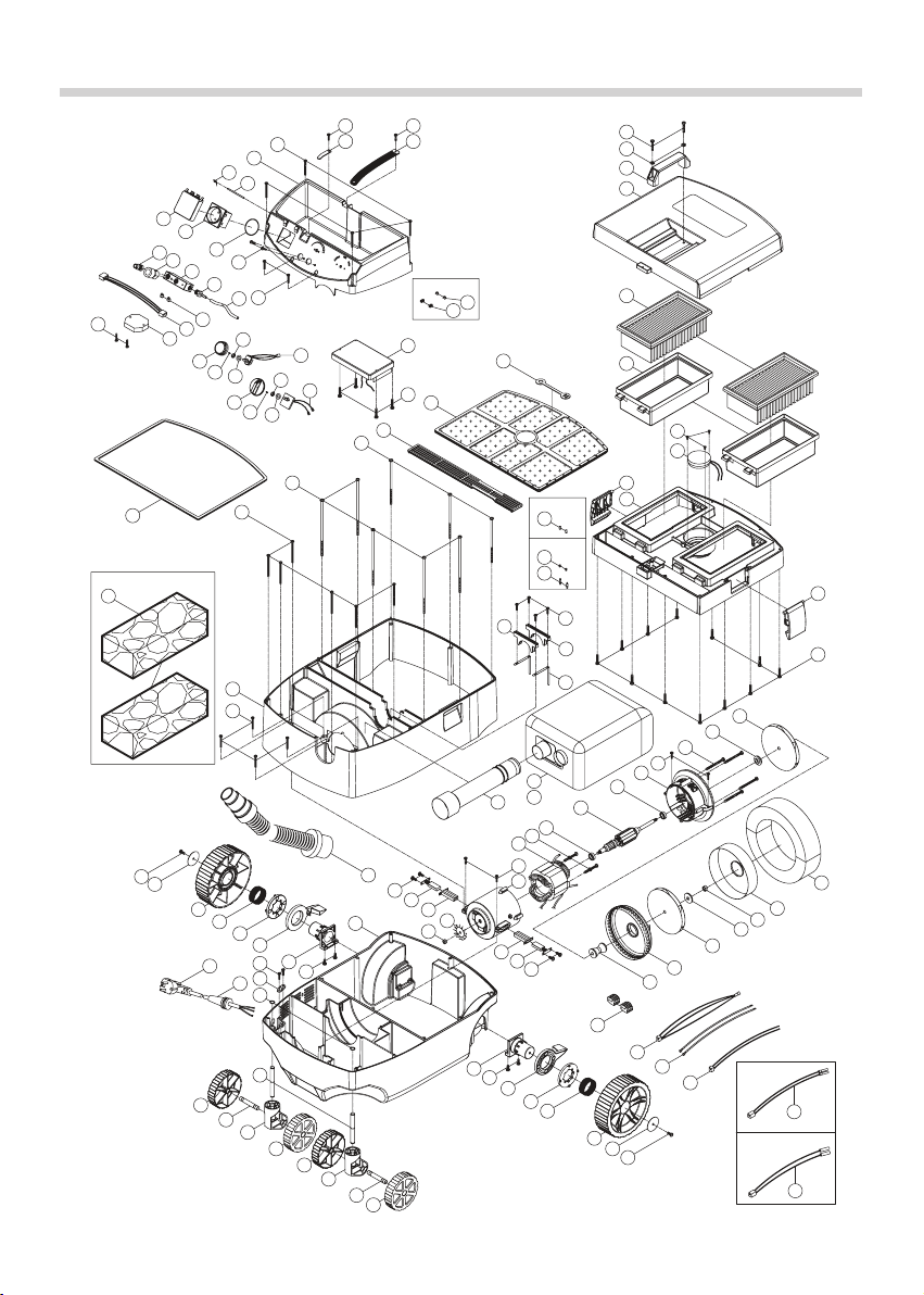
EXPLODED VIEW (Pneumatic Switching Model)
02
01
03 04
05
06
07
25
14
16
17
18
19
20
21
22
22
07
23
28
30
07
31
33
34
35
36
37 38 39
39 38 37
41
40
42
31
43 44 45
46
45
47 31
48
49
55
54
53
52
51
50
59
58
57
60
61
62
63 79
63 79 62
61 60
59 58 57
31
65
68
67
66
69
70
70
70
70
71
72
72
71
27
29
77
78
75
15
56
29
26
07
64
82
80
81
80
83
84
89
91
92
97
96
95
94
93
NO.01~109 V3.1
100
49A
13
12
Optional - A
24
Optional - A
Optional - B
101
102
76
Optional - A
Optional - B
Optional
103
104
105
08 09
99
10
11
99
09-1
09-2
11-1
11-2
32
32A
34C
73
109

13
PARTS LIST (Pneumatic Switching Model)
No. Parts Name Q'ty
50 SPACER-LARGE 1
51 EXHAUST HOUSING 1
52 FLAT ALUMINUM WASHER ø8 x ø25 x 2 1
53 HEX NUT M8 1
54 INTAKE HOUSING 1
55 SOUND DEADENING FOAM 1
56 CHASSIS 1
57 SCREW M6 x 12 2
58 FLAT WASHER ø6 x ø40 x 2.5 2
59 WHEEL-REAR 2
60 SPRING ø2 x ø41.5 x ø45.5 x 4T x 22.6L 2
61 WHEEL LOCK DISC 2
62 WHEEL LOCK LEVER 2
63 REAR WHEEL STUB AXLE 2
64 ELECTRONICS BOARD 1
64 ELECTRONICS BOARD 1
65 CORD CLIP 1
66 POWER SUPPLY CORD 1
67 CORD ARMOR 1
68 EXTERNAL CIRCLIP S-10 2
69 CASTOR SHAFT 2
70 WHEEL-FRONT 4
71 AXLE SHAFT 2
72 CASTOR CARRIER 2
73 THREE WAY CONNECTOR 1
74 N/A -
75 LEAD FOR SUCTION POWER CONTROL 1
76 LEAD FOR FILTER SHAKER 1
77 LEAD FOR INTEGRATED SWITCH APPLIANCE SOCKET 2
78 LEAD FOR LIQUID OVERFLOW SWITCH 1
79 SCREW M5 x 16 4
80 SCREW M4 x 14 2
81 HOSE STRAP 1
82 STRAP HOOK 1
83 PULL STRAP 1
84 O-RING ø47.5 x 2 1
85~88 N/A -
89 SCREW M4 x 12 2
90 N/A -
91 LEAD FOR PNEUMATIC SWITCHING MODULE 1
92 INTEGRATED SWITCHING UNIT 1
93 QUICK RELEASE CONNECTOR ( MALE) 1
93 QUICK RELEASE CONNECTOR ( MALE) 1
94 QUICK RELEASE CONNECTOR ( FEMALE) 1
94 QUICK RELEASE CONNECTOR ( FEMALE) 1
95 CONNECTOR PLATE 1
96 TUBE CONNECTOR 1
97 TUBE 5 x 8 x 70cm 1
98 N/A -
99 SCREW M4 x 4 2
100 RUBBER SEAL 1
101 CONDUCTOR PIN 2
102 SPRING ø0.3 x ø5.5 x ø6 x 5T x 13L 2
103 LEAD FOR FILTER SHAKER 1
104 WET MAIN FILTER 2
105 SCREW M4 x 20 2
106 N/A -
107 N/A -
108 N/A -
109 EAR TYPE CLAMPS 2
No. Parts Name Q'ty
1 SCREW M4 x 38 4
2 TOP PANEL 1
3 TORSION SPRING ø0.7 x ø2.5 x ø3.9 x 21L 1
4 HINGE PIN ø2.3 x 60 1
5 HINGED COVER 1
6 INTEGRATED SWITCHING SOCKET 1
7 SCREW M4 x 25 22
8 SUCTION POWER CONTROL DIAL 1
9 RHEOSTAT 1
9-1 FLAT WASHER 1
9-2 NUT 1
10 SWITCH KNOB 1
11 MAIN SWITCH-4 POSITION 1
11-1 FLAT WASHER 1
11-2 NUT 1
12 SPRING ø0.5 x ø4 x ø5 x 5T x 7.5L 2
13 E-CLIP E-3 2
14 SCREW M5 x 20 2
15 FLAT WASHER ø5 x ø12 x 1 2
16 TOP HANDLE 1
17 TANK COVER LID 1
18 PLEATED MAIN FILTER 2
19 FILTER FRAME 2
20 SCREW M4 x 8 3
21 FILTER SHAKER UNIT 1
22 CATCH 2
23 MAIN TANK COVER 1
24 CONDUCTOR PIN 2
25 DIAPHRAGM FILTER 1
26 VENT COVER 1
27 SCREW M5 x 125 3
28 SCREW M5 x 140 5
29 SCREW M4 x 55 10
30 BODY 1
31 SCREW M4 x 16 10
32 BRACKET 1
32A BRACKET 1
33 COPPER STRIP-FOR OVERFLOW SWITCH 2
34 VACUUM CLEANER BAG 1
34A VACUUM CLEANER BAG ( CLOTH ) 1
34B N/A 1
35 HOSE PORT TUBE 1
36 HOSE 1
37 SCREW M4 x 12 4
38 CARBON BRUSH 7 x 12 x 32 2
38 CARBON BRUSH 7 x 12 x 32 2
39 BRUSH HOLDER 2
40 HEX NUT-LEFT HANDTHREAD M6 1
41 FAN 70 x 6 1
42 MOTOR HOUSING 1
43 STATOR 1
43 STATOR 1
44 STATOR SCREW M5 x 60 2
45 BEARING 6200-2RU 2
46 ARMATURE 1
46 ARMATURE 1
47 MOTOR FRONT COVER 1
48 SPACER-SMALL 1
49 TURBINE IMPELLER 1
49A TURBINE IMPELLER 1

14
EXPLODED VIEW
NO.01~90 V2.8
02
01
03 04
05A
06
07
25
14
16
17
18
19
20
21
22
22
07
23
28
30
07
31
33
34
35
36
37 38 39
39 38 37
41
40
42
31
43 44 45
46
45
47 31
48
49
55
54
53
52
49A
51
50
59
58
57
60
61
62
63 79
63 79 62
61 60
59 58 57
31
65
68
67
66
69
70
70
70
70
71
72
72
71
27
29
77
78
73
75
15
56
13
12
29
26
07
64
82
80
81
80
83
84
86
Optional - A
24
Optional - A
Optional - B
87
88
89
76
Optional - A
Optional - B
90
Optional
32
32A
08 09
85
10
11
85
09-1
09-2
11-1
11-2
05B
34C

15
PARTS LIST
NO. Parts Name Q'TY
45 BEARING 6200-2RU 2
46 ARMATURE 1
46 ARMATURE 1
47 MOTOR FRONT COVER 1
48 SPACER-SMALL 1
49 TURBINE IMPELLER 1
49A TURBINE IMPELLER 1
50 SPACER-LARGE 1
51 EXHAUST HOUSING 1
52 FLAT ALUMINUM WASHER ø8 x ø25 x 2 1
53 HEX NUT M8 1
54 INTAKE HOUSING 1
55 SOUND DEADENING FOAM 1
56 CHASSIS 1
57 SCREW M6 x 12 2
58 FLAT WASHER ø6 x ø40 x 2.5 2
59 WHEEL-REAR 2
60 SPRING ø2 x ø41.5 x ø45.5 x 4T x 22.6L 2
61 WHEEL LOCK DISC 2
62 WHEEL LOCK LEVER (0.033KG) 2
63 REAR WHEEL STUB AXLE 2
64 ELECTRONICS BOARD 1
64 ELECTRONICS BOARD 1
65 CORD CLIP 1
66 POWER SUPPLY CORD 1
67 CORD ARMOR 1
68 EXTERNAL CIRCLIP S-10 2
69 CASTOR SHAFT 2
70 WHEEL-FRONT 4
71 AXLE SHAFT 2
72 CASTOR CARRIER 2
73 THREE WAY CONNECTOR 1
74 N/A -
75 LEAD FOR SUCTION POWER CONTROL 1
76 LEAD FOR FILTER SHAKER (OPTIONAL) 1
77 LEAD FOR INTEGRATED SWITCH APPLIANCE SOCKET 2
78 LEAD FOR LIQUID OVERFLOW SWITCH 1
79 SCREW M5 x 16 4
80 SCREW M4 x 14 2
81 HOSE STRAP 1
82 STRAP HOOK 1
83 PULL STRAP 1
84 O-RING ø47.5 x 2 1
85 SCREW M4 x 4 2
86 RUBBER SEAL 1
87 CONDUCTOR PIN (OPTIONAL) 2
88 SPRING (OPTIONAL) ø0.3 x ø5.5 x ø6 x 5T x 13L 2
89 LEAD FOR FILTER SHAKER (OPTIONAL) 1
90 WET MAIN FILTER (OPTIONAL) 2
91 N/A -
92 N/A -
93 N/A -
NO. Parts Name Q'TY
1 SCREW M4 x 38 4
2 TOP PANEL 1
3 TORSION SPRING ø0.7 x ø2.5 xø3.9 x 21L 1
4 HINGE PIN ø2.3 x 60 1
5 HINGED COVER 1
6 INTEGRATED SWITCHING SOCKET 1
7 SCREW M4 x 25 22
8 SUCTION POWER CONTROL DIAL 1
9 RHEOSTAT 1
9-1 FLAT WASHER 1
9-2 NUT 1
10 SWITCH KNOB 1
11 MAIN SWITCH-3 POSITION 1
11-1 FLAT WASHER 1
11-2 NUT 1
12 SPRING (OPTIONAL) ø0.5 x ø4 x ø5 x 5T x 7.5L 2
13 E-CLIP (OPTIONAL) E-3 2
14 SCREW M5 x 20 2
15 FLAT WASHER ø5 x ø12 x 1 2
16 TOP HANDLE 1
17 TANK COVER LID 1
18 PLEATED MAIN FILTER 2
19 FILTER FRAME 2
20 SCREW M4 x 8 3
21 FILTER SHAKER UNIT 1
22 CATCH 2
23 MAIN TANK COVER 1
24 CONDUCTOR PIN (OPTIONAL) 2
25 DIAPHRAGM FILTER 1
26 VENT COVER 1
27 SCREW M5 x 125 3
28 SCREW M5 x 140 5
29 SCREW M4 x 55 10
30 BODY 1
31 SCREW M4 x 16 10
32 BRACKET 1
32A BRACKET 1
33 COPPER STRIP-FOR OVERFLOW SWITCH 2
34 VACUUM CLEANER BAG 1
34C VACUUM CLEANER BAG (VELCROTYPE ) 1
35 HOSE PORT TUBE 1
36 VACUUM HOSE (INCLUDING CONNECTORS ) 4M 1
37 SCREW M4 x 12 4
38 CARBON BRUSH 7 x 12 x 32 2
38 CARBON BRUSH 7 x 12 x 32 2
39 BRUSH HOLDER 2
40 HEX NUT-LEFT HANDTHREAD M6 1
41 FAN 70 x 6 1
42 MOTOR HOUSING 1
43 STATOR 1
43 STATOR 1
44 STATOR SCREW M5 x 60 2

This manual suits for next models
1
Table of contents
Other AGP Vacuum Cleaner manuals


