manuals.online logo
Brands
  1. Home
  2. •
  3. Brands
  4. •
  5. AGRI EASE
  6. •
  7. Lawn Mower
  8. •
  9. AGRI EASE BE-AGL125F Application guide

AGRI EASE BE-AGL125F Application guide

PURCHASE DATE MODEL NO. SERIAL NUMBER
DEALER
OFFSET
BOOM MOWER
BE-AGLXXXF
OPERATIONS & PARTS MANUAL
FOR MODELS:
• BE-AGL125F
• BE-AGL145F
• BE-AGL165F
TABLE OF CONTENTS
3General Information & Safety
7Set Up
10 Transport & Storage
11 Maintenance Instructions
13 Exploded View & Parts Breakdown
BE-AGLxxxF USER MANUAL 3
GENERAL INFORMATION
INTRODUCTION:
The AG Flails are primarily designed to mow grass, weeds and light brush.
The mowers are assembled for operation with 1000 RPM tractor input only (rated PTO up to 45 HP), and
supplied standard with Cat. I lift pins for tractor attachment.
The mowers can fit Cat. I quick attach hitch by using suitable bushings to adapt diameters of lift pins.
SYMBOLS:
This booklet contains three “safety graphic symbols” which highlight the relevant danger levels or important
information:
DANGER
It draws the operator’s attention to situations which can jeopardize people’s safety.
CAUTION
It draws the attention to situations which jeopardize the machine eciency but not people’s safety.
IMPORTANT
It highlights general information which does not endanger people’s safety or the eciency of the parts.
SAFETY
Safety Labels
The safety labels and the information on the machine, listed in the following table, must be necessarily
read and respected; failure to follow these warnings can cause death or severe injuries. Make sure that the
labels are always present and legible; should this not be the case, contact your nearest dealer to replace the
missing or illegible ones.
4 BE-AGLxxxF USER MANUAL
BE-AGLxxxF USER MANUAL 5
ALLOWED USE:
AG flail mowers, as described in this instruction and maintenance booklet, have been specifically designed to
mow grass, weeds, and light brush up to 1” diameter. Any other use jeopardizes the operator’s safety and the
machine integrity.
IMPROPER USE:
The mower was designed to mow grass, weeds, and light brush only. Only operate this mower on a properly
sized and equipped tractor.
When using AG flail mowers, the following is particularly forbidden:
- The attachment to tractors of unsuitable power or weight.
- To use other than 1000 R.P.M. PTO speed.
- To work in excessively stony grounds.
- To work on excessive slopes.
- To approach the machine while wearing inappropriate work clothing.
- To get on the machine while it is being used or transported.
DANGER
Operating this mower in an application for which it is not designed and/or operating with the wrong size
tractor can cause mower component damage and equipment failure resulting in possible serious injury or
death.
SAFETY IN THE WORKPLACE:
Most of the accidents which take place while the operator is using the machine or the equipment or
during their maintenance or repair are caused by a lack of compliance with the basic safety precautions.
It is necessary, therefore, to become more and more conscious of the potential risks of one’s actions by
constantly paying attention to the eects.
If potentially dangerous situations are known, accidents can be prevented!
OPERATOR’S REQUIREMENTS:
Physical: good eyesight, coordination and capability of carrying out all functions required for the machine’s
use.
Mental: Capability of understanding and applying the established rules and safety precautions. Users must
pay attention and be sensible for their own and other people’s safety.
Training: users must have read and studied this manual, its enclosed graphs and schemes and its
identification and danger plates. They must be skilled and trained on any use or maintenance activities.
WORK CLOTHING:
When working and especially when executing repair or maintenance activities, it is necessary to wear the
following clothing and safety accessories:
• Overalls or other comfortable clothing, not too loose to prevent the possibility that parts of them might be
caught in the moving parts of the machine.
• Protective gloves for hands.
• Protective glasses or faceplate for eyes and face.
• Protective helmet for the head.
• Safety shoes.
Wear only personal safety accessories in good condition
and complying with the rules in force.
6 BE-AGLxxxF USER MANUAL
GENERAL SAFETY RULES
ALWAYS CONSIDER THE FEATURES OF THE AREA WHERE WORK IS TAKING PLACE:
When the equipment is running, it is forbidden to stand within the field of action of the shredder or of the
other accessories of which it is provided with.
PREPARE THE WORK:
• Before and when working, do not drink alcohol, take drugs, or any other substances which may alter your
capability of working with machine tools.
• Be sure to have sucient fuel to prevent a forced stopping of the machine, especially during critical
operations.
• Do not use the equipment under unsafe conditions. For instance, it is forbidden to execute makeshift repair
activities just to start working; it is forbidden to work at night with an insuciently illuminated working
area.
• NEVER operate implement without all shields in place and in good operational condition. The operator
must be familiar with the mower and tractor and all associated safety practices before operating the
mower and tractor.
WHEN WORKING OR DURING THE MAINTENANCE ACTIVITIES IT IS NECESSARY TO REMEMBER:
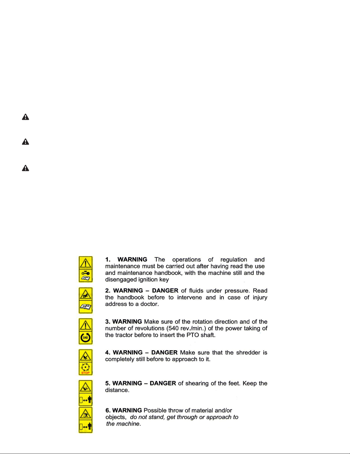
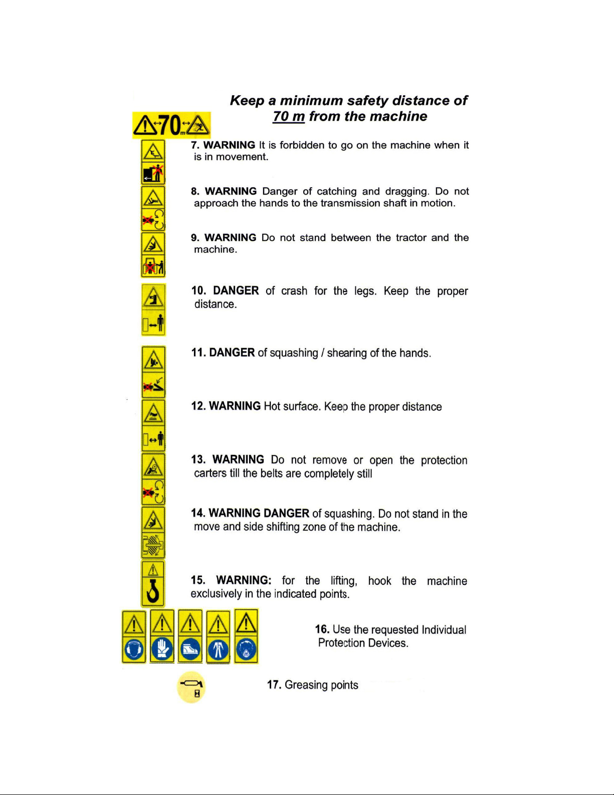
• The labels and stickers providing instructions and pointing out the dangers must not be removed, hidden,
or made illegible.
• Do not remove, except in case of maintenance, the shields, guards, and deflectors equipped on the mower.
When it is necessary to remove them, stop engine, handle with care and reassemble them properly before
restarting the engine and using the equipment. The mower is equipped with protective deflectors to
prevent objects being thrown from the mower by the blades, however, no shielding is 100% eective. All
shields, guards, and deflectors equipped on the mower must be maintained in good operational condition.
• It is forbidden to lubricate, clean and adjust the moving parts while they are running.
• During maintenance or adjustment activities on the equipment it is forbidden to use hands for executing
operations for which there are specific tools.
• Do not use tools in bad condition or inappropriately, for instance pliers rather than monkey spanners, etc.
• When maintenance or repairs are completed, check that no tools, wiping rags, or other materials are left
inside spaces or guides with moving parts.
• While using the equipment, it is forbidden to make more than one person give directions and make signals.
The eventual directions and signals relating to the load handling must be given by one person only.
• Do not unexpectedly call an operator while he is working if not necessary; it is forbidden as well to frighten
or throw objects at the operator.
• Watch out for bystanders, especially children!
• Do not make people get on the machine.
• When the equipment is not needed, stop the vehicle’s engine, park it on flat ground with first speed and
parking brake on, with the machine rested on the ground and PTO disengaged.
• Do not clean, lubricate, repair or adjust with the engine running and the machine lifted.
• Never use the machine on steep slopes which may jeopardize the equipment’s stability.
The manufacturer declines all responsibility for a lack of compliance with these instructions.
BE-AGLxxxF USER MANUAL 7
SET UP
ATTACHMENT TO THE TRACTOR
Before operating the mower, carefully read this Operator’s Manual, completely understand the safety
instructions, and know how to operate both the tractor and the PTO shaft correctly, carefully reading the
instruction manuals of the tractor and PTO shaft manufacturers.
All AG flail mowers have been manufactured to be attached to any tractor provided with hydraulic and
universal 3-point hitch.
The tractor used to operate the mower must have the power, capacity, and required equipment to safely
operate the mower. Operating the mower on improperly sized and equipped tractors may cause tractor and/
or mower damage and could be a potential danger to the operator and passers-by.
Before attaching the implement to the tractor, set both on flat, smooth ground and make sure that nobody is
standing between them.
Move the tractor slowly towards the flail mower by aligning the tractor hydraulic lift arms to the two mower
hitches’ lateral brackets; stop engine and set parking brake.
Connect the lower arms first by removing the release pins of the brackets placed on the plates, inserting the
lift arms into the arms center and fastening them with the relevant release pins, which had been removed.
Then connect the tractor top link to the third upper point by removing the pin located between the plates,
inserting the top link itself and locking it with the pin.
It is always good to make sure that the central gearbox axis is parallel to the ground, thus reducing the stress
on the power takeo and extending the working life of the equipment.
DANGER
Pay attention to the tractor’s front wheels grip when the equipment is set up and lifted; if the wheels
appear to be too lightened, ballast the tractor front tires or add front weights.
CAUTION
After executing the above-mentioned activities it is always good to check that all bolts and nuts of your
shredder are tightened (refer to the torque specifications in this manual).
Adjust the third point so that the upper part of the frame is parallel to the ground. Lock all connection parts
with the special sway chains or tie rods.
8 BE-AGLxxxF USER MANUAL
DRIVELINE ATTACHMENT
Before assembling the PTO shaft, check that its RPM and direction of rotation match those of the tractor.
Moreover, carefully read the instruction manuals of the PTO shaft and the tractor manufacturers. Before
starting work, make sure all safety shields are in place. Check in particular that the safety guards cover
the PTO shaft throughout its extension. When attaching the mower input driveline to the tractor PTO, be
sure that the connecting yoke spring activated locking collar slides freely and the locking balls are seated
securely in the groove on the tractor PTO shaft. A driveline not attached correctly to the tractor PTO shaft
could come loose and result in personal injury and damage to the implement.
CAUTION
Make sure the driveline will not bottom out (at its most compressed position there must be at least a 3/4”
clearance between each profile end and opposite profile universal joint) or become disengaged (at its
farthest extended position a minimum profile engagement of 1/3 of the length must be maintained).
Check that the cardan shaft minimum and maximum length are the ones required by the machine-tractor
coupling. Should problems arise, contact a skilled repair shop or the driveshaft retailer. After installation,
secure safety guards to the tractor and the machine using the special chains and make sure that they pivot
freely. If the PTO shaft is equipped with other safety devices, such as a pair limiter or freewheels, be sure to
install them on the machine side. For PTO use and maintenance, refer to the relevant booklet.
WORKING HEIGHT ADJUSTMENT
The machine’s working height is determined by the position of the rear roller. Lifting the roller moves the
cutters closer to the soil, whereas lowering it moves the cutters farther from the soil. After a modification
of the working height, be sure that the cutters skim the ground; direct contact would cause wear and could
aect the cutting rotor balance and may cause objects to be thrown out from under the mower deck.
FLAIL MOWER ADJUSTMENT
1. On a flat piece of ground, attach the flail mower to the tractor using the three point linkage.
2. Use a solid adjustable top link.
3. Lower the three point linkage to its lowest position.
4. With the roller at the rear in contact with the ground, adjust the length of the top link so that the lower
edge at the side of the flail mower is parallel with the ground.
5. Rotate the blade drum by hand so that a row of blades hang vertically towards the ground.
BE-AGLxxxF USER MANUAL 9
6. Measure the clearance between the bottom of the extended blades and the ground.
• Minimum 50mm
• Note: in rough or lumpy paddocks the clearance needs to be increased to ensure that the blades don’t
impact the ground in operation.
7. Adjust the roller height to increase or decrease the blade clearance as required
8. Go through steps 4-7 until the required clearance is achieved.
When the Flail Mower has been set up with the required tolerances:
Operate the Flail Mower with tractor in low range and the PTO delivering 1000 RPM.
DRIVE BELT ADJUSTMENT
Loosen Screws A and B that lock the support shaft and loosen the counter nut C.
Loosen the screws that lock the gear box on the mounting plate D.
Adjust the drive belt tension. The correct belt tension is achieved when the belt can be deflected by the belt
thickness about 10mm at the center point between the pulleys.
Align the gearbox so the drive shaft is parallel with the body.
Use a straight edge to make sure the belt pullies are inline and running true. If misaligned, call your dealer or
service agent for technical support.
Fit the safety covers and tighten the mounting bolts before operation.
Approx.10mm
Deflection
Align with a
straight edge
10 BE-AGLxxxF USER MANUAL
TRANSPORT & STORAGE
WORKING SPEED
The working speed depends on quality, diameter and height of the material to be cut; for ecient mower
performance it must be between 2 and 5 MPH. The power takeo speed must be 1000 RPM maximum.
Operate the mower at its full rated PTO speed to maintain blade speed for a clean cut.
DANGER
Do not exceed the rated PTO speed for the implement. Excessive PTO speeds can cause driveline or blade
failures resulting in serious injury or death.
ROAD TRANSPORT
Extreme caution should be used when transporting the tractor and implement on public roadways. The
tractor must be equipped with all required safety warning features including an SMV emblem and flashing
warning lights which are clearly visible from the rear of the unit. Make sure you are in compliance with all
local regulations regarding transporting equipment on public roads and highways. Do not exceed 20 MPH
(32 kph). Reduce speed on rough roads and surfaces. Always use hazard flashers on the tractor when
transporting unless prohibited by law.
STORAGE
If your shredder will not be used for a long period of time, respect the following suggestions:
1. Wash the machine thoroughly and dry it.
2. Lubricate all bearings with enough grease to eliminate any cavities where water condensation may occur
and cause damage. Refer to “Maintenance of the Machine” for location of all grease fittings. Be sure the
vent on top of the gearbox is open.
3. Loosen the set nut and spindle jack to relieve drive belt tension (NOTE: Before next season’s use, be sure
to adjust the drive belt tension.)
4. Coat all exposed surfaces inside the mower with oil or grease to prevent rusting and pitting during
storage.
5. Protect the whole machine with a tarpaulin and store it in a dry place.
PRE-SEASON CHECK
1. Check the oil level in the gearbox and lubricate all bearings. See “Lubrication.”
2. Adjust drive belt tension. See “Belt Drive.”
3. Check all equipment and replace damaged or worn parts.
4. Tighten all bolts and nuts. See “Torque Specifications.”
5. Inspect for missing and/or broken blades/knives. Replace as necessary. See “Knife Replacement.”
6. Be sure that the safety guards are in place and secure.
7. Run the flail mower at a low RPM checking to make sure that all driveline parts are moving freely.
BE-AGLxxxF USER MANUAL 11
MAINTENANCE
Maintenance is a fundamental operation to extend the life and performance of any agricultural vehicle;
taking care of the machine grants you not only proper eciency and execution, but also a longer life of all
the equipment and greater safety of the workplace.
The operating times indicated in this manual have just an informative character and refer to normal
conditions of use; they can thus undergo variations according to the type of service.
CAUTION
Before injecting lubricating grease into the zerks, clean them thoroughly to prevent mud, dust, or other
foreign matters from mixing up with grease, thus diminishing the lubrication eect.
• When adding or changing oil, it is better to use the same oil type, in order to avoid mixing oils with
dierent features.
• Before executing maintenance activities on the machine, stop the engine, disengage the power takeo,
set the parking brake and place the equipment on the ground in horizontal position.
• After the first working hours, check that all bolts and nuts are tightened; remember to also often check
all the machine safety guards.
FIRST CHECK
• Check the correct tension of the driving belt.
• Check that all bolts and nuts are tightened.
• After the first 50 hours of work, change oil in the gearbox.
EVERY 8 HOURS OF WORK
• Rotate teardrop shaped plate B and grease the shaft support (driveline side) through lubricating nipple A
(picture 1).
• Grease the shaft support (external side) through lubricating zerk A (picture 2).
• Grease the shaft support (driveline) and the belt tensioner idler pin through lubricating zerks A and B
(picture 3).
• Grease the stabilizing roller through lubricating zerk A (picture 4).
EVERY 50 HOURS OF WORK
• Check the tension of the driving belt.
• Check that all bolts and nuts are tightened.
• Check the cutters/hammers for wear.
• Check the overgear unit oil level through plug A (picture 5).
EVERY 500 HOURS OF WORK
• Check that all bolts and nuts are tightened.
• Change oil in the overgear unit.
EVERY 1000 HOURS OF WORK
Replace the driving belt.
GEAR BOX MAINTENANCE
• The oil should be drained out and replaced after the first 50 hours of operation. Then the oil should be
changed every 250 hours, or at least once a year.
• Drain the oil from the gearbox thoroughly. Check and clean it. Fill with new gear oil up to the dedicated oil
level.
• The draining procedure is as follows: remove the draining bolt under the gear box so that the oil drains o.
After the oil is drained, put the plug back and fill with gear oil up to the dedicated oil level.
12 BE-AGLxxxF USER MANUAL
8HRS / DAILY 50HRS / WEEKLY ANNUALLY
Lubricate PTO Shaft X X X
Lubricate Caster Wheels X X X
Lubricate Blade Spindle X X X
Check Gear Box Oil Level X X
Clean Machine X
Lubricate and Clean PTO
Shaft Cover X
PTO SHAFT MAINTENANCE
The PTO shaft is designed to telescope to allow for dimensional changes as the machine goes through its
operating range. A tubular guard encloses the driving components and is designed to turn relative to the
driving components. The shaft should telescope easily and the guard should turn freely on the shaft at all
times. Annual disassembly, cleaning and lubrication is recommended to insure that all components function
as intended. To maintain the shaft, follow this procedure:
1. Remove the shaft from the machine.
2. Pull shaft apart.
3. Use a screwdriver to pry the tabs out of the sleeves on each end.
4. Pull the shaft out of the plastic tubular guard.
5. Use a solvent to clean the male and female portions of the telescoping ends.
6. Apply a light coat of grease to each end.
7. Clean the grooves on each end where the tabs are located. Clean each tab also.
8. Apply a light coat of grease to each groove.
9. Insert the shaft into its respective guard and align the slots with the groove.
10.Insert the tabs through the slots and seat in the groove.
11. Check that each guard turns freely on the shaft.
12. Assemble the shaft.
13. Check that the shaft telescopes easily.
14. Replace any components that are damaged or worn.
15. Install the shaft on the machine.
BE-AGLxxxF USER MANUAL 13
1-1
REF SYSTEM NO. PART NO. DESCRIPTION QTY
1 503010763 DIN985-M12 Thin nut 8
2 506010057 GB97.1-12 Flat gasket 8
3509010008 GB1152-M8X1 Oil cup 2
4 810240078 EFAGL165A-1200-00 Roller hanging board (L) 1
5 501011126 GB5783-M12X30 Screw bolt 8
6 511040007 EF100.00.012 UC205 bearing 2
7 501011888 GB5786-M14X1.5X40 Screw bolt 2
8 506010058 GB97.1-14 Flat gasket 4
9 503010764 DIN985-M14 Thin nut 2
10-1 710420001 EFAGL105A-0000-01 (L=1021) Scraper (105) 1
10-2 710280001 EFAGL125A-0000-01 (L=1221) Scraper (125) 1
10-3 710260001 EFAGL145A-0000-01 (L=1421) Scraper (145) 1
10-4 710240014 EFAGL165A-0000-03 (L=1621) Scraper (165) 1
10-5 710390001 EFAGL185A-0000-01 (L=1821) Scraper (185) 1
11-1 801140004 EFG100.012 (L=1027) Roller (105) 1
11-2 801160017 EFG120.012 (L=1227) Roller (125) 1
11-3 801180004 EFG140.012 (L=1427) Roller (145) 1
11-4 801200004 EFG160.012 (L=1627) Roller (165) 1
11-5 810390011 EFAGL185A-0400-00 Roller (185) 1
12 810240080 EFAGL165A-1300-00 Roller hanging board (R) 1
13 505011721 GB70.3-M8X20 Sunk screw 8
EXPLODED VIEW & PARTS LISTS
1-1
14 BE-AGLxxxF USER MANUAL
REF SYSTEM NO. PART NO. DESCRIPTION QTY
14 810240086 EFAGL165A-1600-00 Sliding rail 2 1
15 700920111 EF100.00.122B Board or chain 1
16 700920107 EF100.00.121 Board or chain 1
17 506010056 GB97.1-10 Flat gasket 11
18 700920108 EF100.00.122 Wide board or chain 10
19 700920109 EF100.00.122A Wide board or chain (L) 1
20-1 810420010 EFAGL105A-0200-00 (L=1086) Rod for board (105) 1
20-2 810280007 EFAGL125A-0200-00 (L=1274) Rod for board (125) 1
20-3 810260005 EFAGL145A-0200-00 (L=1474) Rod for board (145) 1
20-4 810240062 EFAGL165A-0400-00 (L=1674) Rod for board (165) 1
20-5 810390006 EFAGL185A-0200-00 (L=1874) Rod for board (185) 1
21 506030035 GB93-8 Spring washer 1
22 501011100 GB5783-M8X25 Screw bolt 1
23 810240089 EFAGL165A-1700-00 Sliding rail 1 1
24-1 810440001 EFAGL105C-0100-00 (105C) Main body (105) 1
24-2 810360001 EFAGL125C-0100-00 (125C) Main body (125) 1
24-3 810350001 EFAGL145C-0100-00 (145C) Main body (145) 1
24-4 810340014 EFAGL165C-0100-00 (165C) Main body (165) 1
24-5 810410001 EFAGL185C-0100-00 (185C) Main body (185) 1
BE-AGLxxxF USER MANUAL 15
1-2
REF SYSTEM NO. PART NO. DESCRIPTION QTY
1501011131 GB5783-M12X55 Screw bolt 2
2 506030037 GB93-12 Spring washer 10
3 506010057 GB97.1-12 Flat gasket 10
4 503010047 GB6170-M12 Hex nut 2
5 810240082 EFAGL165A-1400-00 Gear box pull rod 2
6 810240065 EFAGL165A-0500-00 Gear box seat 1
7 801240040 XH50.300Z.02W (EFGC884) Gear box 1
8 802710038 EFAGL125.014 Tensioning plate 1
9 501011126 GB5783-M12X30 Screw bolt 6
10 501011129 GB5783-M12X45 Screw bolt 2
11 503010100 GB6172.1-M12 Thin nut 2
12 702420030 EF100.00.177 Rust proof cover 1
13 501011111 GB5783-M10X20 Screw bolt 2
14 506030036 GB93-10 Spring washer 2
15 506010036 GB96.1-10 Large flat gasket 2
16 703400008 FM120.00.199 PTO cover 1
17 710240027 EFAGL165A-0000-06 ROP set pin 1 1
18 506010037 GB96.1-12 Large flat gasket 2
19 701680001 EFGCHM120.101 Plywood 1
20 501011128 GB5783-M12X40 Screw bolt 2
21 503010763 DIN985-M12 Thin nut 2
22 700080010 200.56.011 Lock pin 1
1-2
16 BE-AGLxxxF USER MANUAL
1-3
REF SYSTEM NO. PART NO. DESCRIPTION QTY
1 501011126 GB5783-M12X30 Screw bolt 3
2 710340013 EFAGL165C-0000-06 Tensioning wheel hanging plate 1
3 503010763 DIN985-M12 Thin nut 2
4 503010740 DIN985-M16X1.5 Thin nut 3
5 515010005 REACH04-33X60 Power lock 1
6 701160007 EFG120.106A Big belt pulley (3 grooves) 1
7 503010046 GB6170-M10 Hex nut 2
8 506030036 GB93-10 Spring washer 4
9 506010056 GB97.1-10 Flat gasket 6
10 710340001 EFAGL165C-0000-01 Pulley cover 1
11 501011127 GB5783-M12X35 Screw bolt 3
12 506010057 GB97.1-12 Flat gasket 9
13 710340009 EFAGL165C-0000-02 Protection plate 1
14 506030037 GB93-12 Spring washer 4
15 503010047 GB6170-M12 Hex nut 3
16 501011112 GB5783-M10X25 Screw bolt 4
17 514010001 17X991 Belt 3
18 701160006 EFG120.105A Small belt pulley 1
19 515010001 REACH04-35X60 Power lock 1
20 710340012 EFAGL165C-0000-05 Tensioning gasket 1
21 810340018 EFAGL165C-0200-00 Pull rod 1
22 710340010 EFAGL165C-0000-03 Spring locating cover 2
23 810340021 EFAGL165C-0300-00 Tensioning wheel 1
24 710340011 EFAGL165C-0000-04 Tensioning spring 1
25 701240046 EFGC120.138 U cap 1
1-3
BE-AGLxxxF USER MANUAL 17
1-4
REF SYSTEM NO. PART NO. DESCRIPTION QTY
1 501011127 GB5783-M12X35 Screw bolt 4
2 506030037 GB93-12 Spring washer 9
3 701520006 EFG120.168 Oil nipple 1
4 701520010 EFG120.169 Paper pad 1
5 511040032 UC207 Bearing 2
6-1 801140006 EFG100.013 (L=1003) Blade shaft (105) 1
6-2 801160021 EFG120.013 (L=1203) Blade shaft (125) 1
6-3 801180006 EFG140.013 (L=1403) Blade shaft (145) 1
6-4 801200006 EFG160.013 (L=1603) Blade shaft (165) 1
6-5 810390008 EFAGL185A-0300-00 Blade shaft (185) 1
7 510020417 GB13871-FB-55X80X8 Oil seal 1
8 501011126 GB5783-M12X30 Screw bolt 4
9 510013224 GB3452.1-G-34.5X3.55 Sealing ring 1
10 710240029 EFAGL165A-0000-08 Oil seal cover 1
11 501011125 GB5783-M12X25 Screw bolt 1
12 701160033 EFG120.103 Rabbet board 1
13 501014721 EF120.00.200 M12X1.5X78 bolt 20
14 700920091 EF100.00.101 Spacer bush 40
15-1 701110023 EFR105.102 Y blade 40
15-2 701140011 EF100.00.102B Hammer 20
16 503010738 DIN985-M12X1.5 Thin nut 20
17 509010008 GB1152-M8X1 Oil cup 2
1-4
18 BE-AGLxxxF USER MANUAL
1-5
BE-AGLxxxF USER MANUAL 19
1-5
REF SYSTEM NO. PART NO. DESCRIPTION QTY
1 802710100 EFAGL125.030 (L=400) Support leg 2
2 703140001 MFP120.00.101 Seal cap 2
3 800920101 EF100.00.111A Square cotter 2
4 802710045 EFAGL125.017 Rear swing arm 1
5 511050221 SF-2-30X34X30 Self-lubricating bear-ing 4
6 509010009 GB1152-M10X1 Oil cup 5
7 501011098 GB5783-M8X16 Screw bolt 2
8-1 810240073 EFAGL165A-1000-00 Side-sway cylinder 1
8-2 810420012 EFAGL105A-0300-00 (105) Side-sway cyl-inder 1
9 705190066 1CM-18-16WD M18X1.5-M16X1.5 Transit joint 2
10 511050222 SF-2-65X70X40 Self-lubricating bear-ing 2
11 802710094 EFAGL125.109 Long pin 2
12 501014929 GB5785-M24X1.5X90 Half-thread bolt 1
13 710240015 EFAGL165A-0000-04 Pusher 1
14 810240096 EFAGL165A-1900-00 Puller 1
15 501010829 GB5782-M24X80 Half-thread bolt 1
16 503010769 DIN985-M24 Thin nut 7
17 511050220 SF-2-30X34X40 Self-lubricating bear-ing 4
18 810240061 EFAGL165A-0300-00 Front swing arm 1
19 501011111 GB5783-M10X20 Screw bolt 4
20 506030036 GB93-10 Spring washer 4
21 506010056 GB97.1-10 Flat gasket 4
22 800920138 EF100.00.019A Upper pull rod pin 1
23 809820065 AGFR245-2500-00 Fixing sleeve 4
24 810250001 EFAGL165B-0100-00 Hanging weldment 1
25 802710093 EFAGL125.108 Step pin 1
26 810240069 EFAGL165A-0600-00 Deflection cylinder 1
27 802710089 EFAGL125.103-MH Lockpin rivet 1
28 509010007 GB1152-M6 Oil cup 2
29 506030035 GB93-8 Spring washer 2
30 501011233 GB5783-M24X65 Screw bolt 1
31 802710092 EFAGL125.107 Short pin 1
32 810240091 EFAGL165A-1800-00 Rear swing arm seat 1
33 700250036 1CB-18-06WD M18X1.5-G3/8 joint 2
34 710240030 EFAGL165A-0000-09 Pressing ring 1
35 503020346 GB812-M24X1.5 Round nut 1
36 802710090 EFAGL125.104-MH Long lock pin rivet 1
20 BE-AGLxxxF USER MANUAL
1-6
REF SYSTEM NO. PART NO. DESCRIPTION QTY
1 703820055 QUICK-COUPLING-G1/2-G G1/2 pin end 4
2 810250003 EFAGL165B-0200-00 Pipeline 2
3 810250005 EFAGL165B-0400-00 Pipeline 1
4 810250004 EFAGL165B-0300-00 Pipeline 1
1-6

This manual suits for next models

2

Other AGRI EASE Lawn Mower manuals

AGRI EASE BE-FM RDG Series Application guide

AGRI EASE

AGRI EASE BE-FM RDG Series Application guide

Popular Lawn Mower manuals by other brands

Craftsman 25915 instruction manual

Craftsman

Craftsman 25915 instruction manual

Gardol GEM-E 1536 Original operating instructions

Gardol

Gardol GEM-E 1536 Original operating instructions

Flymo Mow n Vac HV2800 Original instructions

Flymo

Flymo Mow n Vac HV2800 Original instructions

Southern States SP25PH48STB owner's manual

Southern States

Southern States SP25PH48STB owner's manual

Scag Power Equipment SZL36H-18FR Operator's manual

Scag Power Equipment

Scag Power Equipment SZL36H-18FR Operator's manual

Toro 20786 Operator's manual

Toro

Toro 20786 Operator's manual

White Outdoor LT-542K, LT-942K, LT-946K Operator's manual

White Outdoor

White Outdoor LT-542K, LT-942K, LT-946K Operator's manual

Sidewinder SuperPivot Operator's manual

Sidewinder

Sidewinder SuperPivot Operator's manual

Toro 74401 Operator's manual

Toro

Toro 74401 Operator's manual

Craftsman 917.388013 owner's manual

Craftsman

Craftsman 917.388013 owner's manual

Troy-Bilt 420 Series Operator's manual

Troy-Bilt

Troy-Bilt 420 Series Operator's manual

Mountfield SPL 410 Operator's manual

Mountfield

Mountfield SPL 410 Operator's manual

Toro DH 200 Setup instructions

Toro

Toro DH 200 Setup instructions

Husqvarna Royal 146 S instruction manual

Husqvarna

Husqvarna Royal 146 S instruction manual

Neuton CE 6.2 Safety and operating instructions

Neuton

Neuton CE 6.2 Safety and operating instructions

Victor Tools G287 Instructions for use

Victor Tools

Victor Tools G287 Instructions for use

Husqvarna TS 142 Operator's manual

Husqvarna

Husqvarna TS 142 Operator's manual

Ferris 1000ZK21/48 Operator's manual

Ferris

Ferris 1000ZK21/48 Operator's manual

manuals.online logo
manuals.online logoBrands
  • About & Mission
  • Contact us
  • Privacy Policy
  • Terms and Conditions

Copyright 2025 Manuals.Online. All Rights Reserved.