AGRICOW BRUSH Specification sheet

PENDULUM BRUSH
Use and Maintenance Instructions
1
EN
1
VERSION BRUSHES PENDULUM
USE &
MAINTENANCE MANUAL
General Features
Use and Maintenance Instructions
EN
WARNING:
Please read these instructions carefully before using the machine and keep them safe for future use
Compiled according to Machinery Directive 2006/42/CE, Annex I, point 1.7.4

PENDULUM BRUSH
2
PENDULUM BRUSH
2
MACHINE DESCRIPTION
Cattle Brushing Machine (BRUSH) Pendulum
Description:
The AGRICOW BRUSHING MACHINE has been designed to facilitate a more hygienic and efficient clea-
ning of cattle, while rationalising costs with respect to traditional manual cleaning.
AGRICOW owns Italian patent No. BS2005A000032, relating to “Apparatus for brushing cattle” and the
equivalent European patent No. EP 1665927 B1 valid in the member states of the European Patent
Convention.
The cattle brush is:
• safefortheanimalsandpersonsworkingintheshed
• easytoinstall,notrequiringbrickwork
• easytouse
• operatedatlowenergycost(0.55Kw)
• reliableandeasytomaintain
In compliance with current standards for the safety of persons and things, the machine has been desig-
ned to conform with the applicable requisites as stated in Directive 2006/42/CE issued in May 2006.
As prescribed in the aforementioned standards, the machine is supplied with:
• DeclarationofConformityissuedbytheManufacturer;
• CEmarking;
• Identityplateshowing:
- Name of manufacturer
- Place where machine was made
- Machine type and serial number
- Year of construction

PENDULUM BRUSH
PENDULUM BRUSH
Use and Maintenance Instructions
3
EN
Use and Maintenance Instructions
3
EN
Technical data:
N. motori
1
Tensione di alimentazione
220V – 110V
Frequenza
50 – 60 Hz
Potenza
0,75 Cv
Consumo
0,55 Kw/h
Peso dell’assieme
Kg 80
Dimensione spazzola
50x100
Durata di rotazione pre(pre(preimpostata) Ca 90
sec
Velocità di rotazione
50 giri/min
Picchi di corrente massimi 0 A – 12 A efficace
Temperatura di esercizio -15°C + 55 °C
Protezione motore Fusibile 10 A
USING THE MACHINE
Inspection and controls before use:
ThemachineischeckedonAgricowpremisesbeforedeliveryasforeseenbyinternalprocedures.
Use:
The cattle brush has been designed and produced for use as a system for cleaning the coat of dairy cows. One
brush should be used for every 50/60 cows.
IT MUST NOT BE USED for any purpose other than cleaning the coat of cattle.
Activation:
•Whentheanimalpushesagainstthebrush,amicroswitchstartstoturntheroller,which
automatically proceeds to clean the animal without requiring assistance by staff.
•Bymeansofthestartmotorcontact,theboardcontrolsthestartandendofaworkcycle.
When the device is started, the electronic board begins a brush rotation procedure which
lasts 90 seconds. When the device is started again, the motor turns in the opposite direction
to the previous cycle so the brush is used evenly.
DICHIARAZIONE DI CONFORMITÀ CE
Overall dimension
No. motors
Voltage supply
Frequency
Capacity
Consumption
Overall weight
Brush dimension
Rotation time (preset)
Rotation speed
Maximum power surges
Operating temperature
Motor protection
110x175h cm
1
220V – 110V
50 – 60 Hz
0.75 Cv
0.55Kw/h
80kg
50x100
Approx. 90 sec
36 rev/min
0 A – 12 A effective
-15°C + 55 °C
10 A fuse
Pendulum

PENDULUM BRUSH
4
PENDULUM BRUSH
(In compliance with the EC Machinery Directive 2006/42/EC e s.m.i., Annex II/A)
The company AGRICOW Srl - Via Caduti del Lavoro, 88 - 25013 Carpenedolo - (Brescia) Italy
Declares, on its own responsibility , that the machine
CLEANING BRUSH MACHINE
Description : Brush machine for the automatic cleaning of cattle coats
MODELS:
Year of construction : 2005
The machine complies with the requirements set out in the Directive 2006/42/ CE and subsequent
amendments and additions , enforced in Italy with Legislative Decree dated 17/2010 – Machinery
Directive .
It complies with the following standards and directives:
Electromagnetic-compatibilityEuropeanDirective2014/30/UE;
European Directive 2014/35/UE on low.voltage electric compatibility :
EN12100:2010Safetyofmachinery–Basicconcepts,generalprinciplesfordesign-Riskassessment
andriskreduction;
Nameandaddressofthepersonauthorisedtocompilethetechnicalle;
Name and Surname: Alberto Musicco
Address : Via Caduti del Lavoro, 88 - 25013 Carpenedolo - (Brescia) Italy
Carpenedolo (BS) lì 1 0ttobre 2018
Alberto Musicco
(Legale Rappresentante)
SINGLE BRUSH
MOONBRUSH
SINGLE BRUSH
TOY
PENDULUM
BRUSH
DOUBLE
BRUSH
The identification plate with CE
marking shall be affixed visibly,
legibly and indelibly on the
carpentry parts of the machine
CE DECLARATION OF CONFORMITY

PENDULUM BRUSH
PENDULUM BRUSH
Use and Maintenance Instructions
5
EN
SAFETY INSTRUCTIONS
ENSURE THAT THE DEVICE IS ONLY USED BY PERSONS WITH ADEQUATE TECHNICAL SKILLS.
The operation, maintenance and start-up of the machine must only be carried out by trained and
authorized personnel.
KEEP CHILDREN AND THE ELDERLY OR INFIRM FAR FROM THE DEVICE.
FOLLOW THE SAFETY AND MAINTENANCE INSTRUCTIONS.
RESIDUAL RISKS
Risks for persons:
The safety of persons and things can be compromised if, while the machine is running:
•Coversprovidedformovingpartsareopened.
•Safetysystemsareremoved.
•Anydamagetothecontrolsystemisnotrepairedimmediately.
•Theelectronicboardismodiedbyunauthorisedstaff.
•Themachineisstarted,foratestordemonstration,beforebeingaccuratelyfastenedtothe
support structure.
Caremustalsobetakentopreventriskstopersonsandthingsassummarisedbelow:
•Avoiddamagetothemachineassembly,commandsandbrushduringtransportandhandling
before installation.
•Anykindsofinterventionsonthemachinemustonlybecarriedoutwhenthemachineisswitchedoff.
•Donotmoveclosetothemachinewithopengarmentsorlonghairuntied
•Installthemachineinawell-ventilatedspacefarfromsourcesofelectromagneticpollution.
•Trainassignedstaffonhowtousethemachineandcarryoutmaintenance.
Risks to the animals:
Thanks to its electronic control, the cattle brushing machine is safe for the animals. The aspects
characterising this safety are:
Motor force control•
•Themotor’smaximumtractiveforceisprogrammedtocontrolanycriticalsituationsforthe
animal such as, for example, the tail becoming trapped in the roller.
Inversion of rotation when meeting resistance in the presence of an obstacle•
•Ifthemaximumforceisexceeded,thebrushinvertsdirectionandrotatesintheopposite
direction for 1 minute, after which it returns to rest position.
EMISSIONI DI RUMORE AEREO
Warning: The length
of the end part of the
cow’s tail should NOT
exceed 5-10 cm

PENDULUM BRUSH
6
PENDULUM BRUSH
PRODUCTION OF NOISE
Notsignicantintheworkingarea.
WARRANTY
The warranty is valid for 24 months or 10,000 hours of machine operation. The warranty period
begins on the delivery date of the machine.
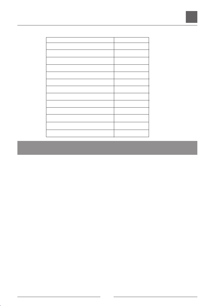
The warranty issued by Agricow applies to the mechanical and electrical parts of the brush,
including the:
1) motor
2) gearbox
3) electronic board
4) sensor
This warranty covers the repair and/or replacement of parts damaged due to an ascertained material
fault or construction defect.
The part whose replacement or repair is claimed must not be returned to Agricow to be checked
without its prior consent. The checks and verification of the anomaly will be carried out by the
specialist personnel in charge.
Mechanical parts of the brush, such as motors and gearboxes out of warranty must be disposed of
locally and should in no way be returned to Agricow.
The warranty excludes the costs of labour incurred from customer service for the replacement of faulty
components or costs incurred for travel to the customer site.
The replacement or repair will be carried out in the shortest time possible, subject to written notice,
consistent with the commitments of the manufacturer and its organized persons, with no obligation to
provide compensation and/or reimbursement for direct or indirect damages.
The warranty excludesbreakdownsduetotransportationbyanymeansotherthanAGRICOWvehicles,
poor or incorrect connection or connection to electrical systems with insufficient flow, failure to comply
with the provisions regarding the installation of the brush, failure to perform the periodic maintenance,
negligence or inability to use, tampering by non-authorized personnel and, in any case, caused by
persons other than AGRICOW employees.
Thetransportcostsandrisksforrepairswillbeentirelybornebytheuser.
The warranty becomes automatically void if:
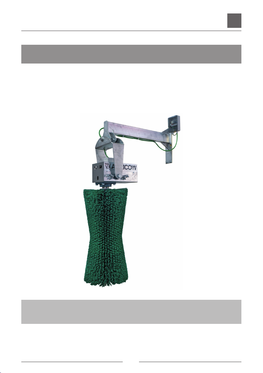
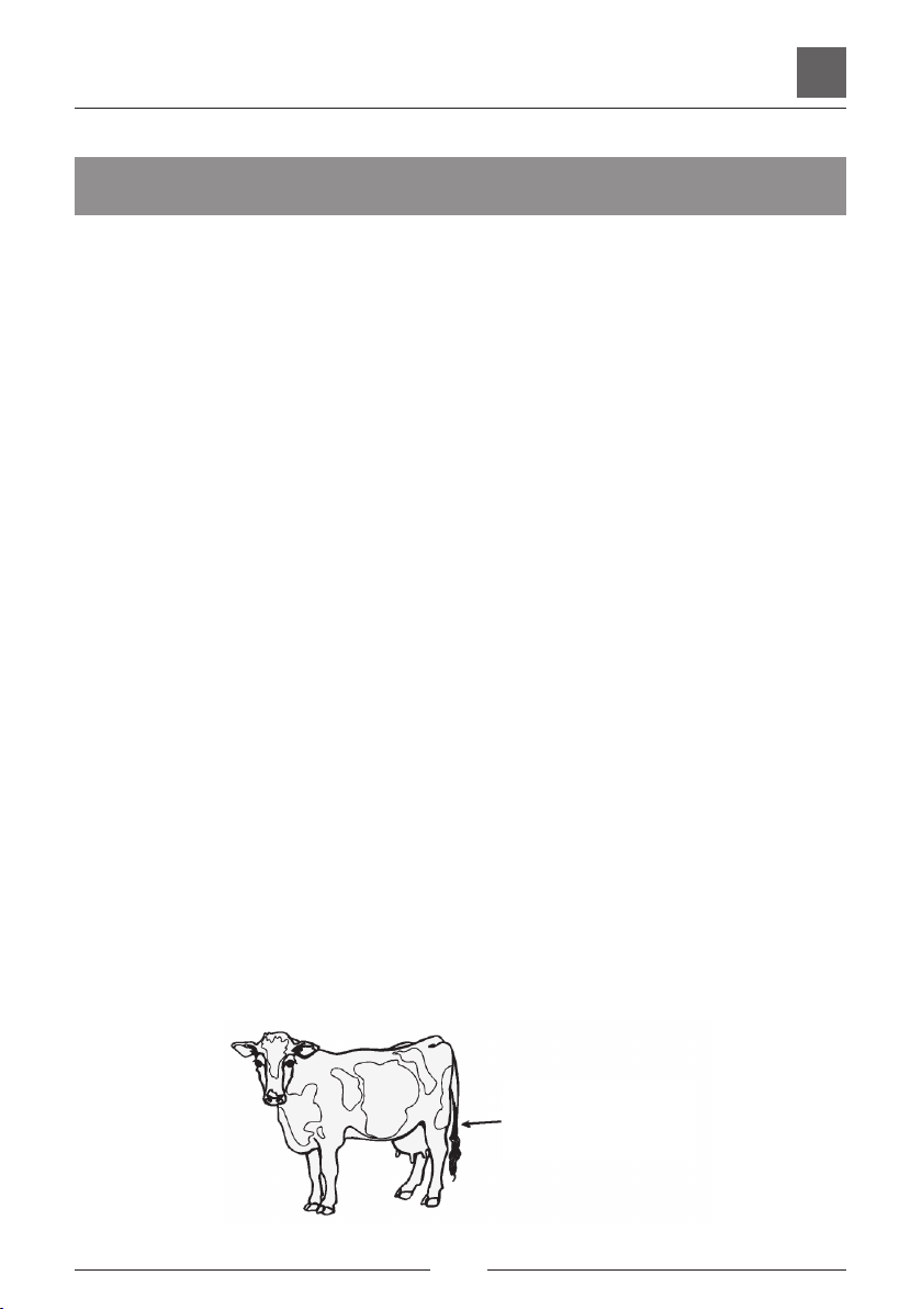
1) The machine is used for purposes other than those for which it is intended, that is, the
cleaning of the coats of cattle.
2) Non-original spare parts are used.
3) Changes are made to the machine without the written consent of Agricow.
4) The dedicated magnetothermal differential switch has not be installed.
5) The brush is used for more than 50-60 cows.

PENDULUM BRUSH
PENDULUM BRUSH
Use and Maintenance Instructions
7
EN
THE WARRANTY ONLY COVERS BREAKDOWNS REPORTED IN TEXTUAL FORM, THAT IS, IN WRITING,
VIA FAX OR E-MAIL WITHIN THE VALIDITY PERIOD OF THE WARRANTY. ONCE THE VALIDITY PERIOD
HAS EXPIRED, REPORTED BREAKDOWNS WILL NOT BE ACKNOWLEDGED.
Claims concerning the parts of the brush covered by warranty under the aforementioned terms
will only be considered if accompanied by the following documents:
- A copy of the invoice showing the date of delivery to the end customer:
- Serialnumberofthebrush,shownonthelabelbearingtheAGRICOWtrademark
- Photoofthemotorand/orgearboxlabel;photooftheelectroniccardbearingthesensorerror
number.
It is also understood that AGRICOW is not liable for any direct or indirect damages caused to
persons or things by defects and breakdowns of the machine or resulting from forced suspension
in its use.
PERIODIC MAINTENANCE
Maintenance foreseen:
All maintenance operations on the machine must be carried out with the power supply switch turned off.
The inside of the machine must not be cleaned with jets of water, which would compromise the electric
components, but using compressed air and brushes.
The machine body must be cleaned each month, removing any residue, and the bearings must be greased
using a normal commercially-sold lubricant.
Spazzola Pendolare - Punti di ingrassaggio
Greasing Points

PENDULUM BRUSH
8
PENDULUM BRUSH
INSTALLAZIONE E MONTAGGIO
Assembly instructions:
The installation of THE Pendulum BRUSH consists of mounting it to the wall/girder using specific fastening systems,
followed by connection to the electrical system, which must be carried out by qualified personnel.
Optimal positioning and stable fastening are particularly important for the correct operation of the Agricow
pendulum brush. It is thus important to ensure that the mounting surface is stable and not exposed to vibrations
or movement.
Agricow advises against outdoor installation. Should this be necessary, it is mandatory to shelter
the box containing the electronic board and the box containing the sensor from rain or excessive
sunlight.
CAUTION:
The brush MUST be installed with the dedicated magnetothermal differential switch.
The procedures for installing the Pendulum brush are shown below.
The roller can be inserted in either direction.
The Pendulum brush is supplied with the machine body completely assembled and ready for installation,
excluding the assembly of the:
•SUPPORTBRACKET,WHICHMUSTBEFASTENEDTOTHEWALLSOTHATTHEBRUSHSUPPORT
CANBEHOOKEDTOIT(Fig.I,2,3,4)
•ELECTRICALCABLE,TOBEFASTENEDINSIDETHECLIPSALREADYPOSITIONEDONTHEARM
SUPPORT (Fig. 5)
•providetokeepatleast45cmor17,72”freebetweentheexistingcableandtherstclip
(fig.5).
INSTALLATION AND ASSEMBLY

PENDULUM BRUSH
PENDULUM BRUSH
Use and Maintenance Instructions
9
EN
INSTALLATION AND ASSEMBLY
Fig. 1 Fig. 2
Fig. 3 Fig. 4
Fig. 5
cable free 45 cm / 17.72”

PENDULUM BRUSH
10
PENDULUM BRUSH
Recommended installation height
ATTENTION:Theheightofthebrushmustaccommodatethedifferentshoulder’sheightoftheanimal
(75/90 cm or 29,52”/35.43”). SEE PIC .
12.0 cm
48.5 cm
23.6 cm 23.1 cm
1.8 cm
3.8 cm
1.1 cm
1.1 cm
3.0 cm
1.8 cm
75 / 90 cm
101 cm
175 cm
PARTICOLARE PIASTRA
48.5 cm
45 cm
17,72”
19,094”
68,90”
Book Plate
29,52” / 35.43”
39.76”

PENDULUM BRUSH
PENDULUM BRUSH
Use and Maintenance Instructions
11
EN
SISTEMA ELETTRONICO
DESCRIPTION OF CONTROL PANEL AND DISPLAY
3-wire sensor
Fig. B Control Panel
R22 TRIMMER FOR
REGULATING PEAK POWER
THRESHOLD FROM 0 TO
12Arms POWER SUPPLY
DL1 RED LED
POWER FUSE
10A (12,5A
SL49A)
MESSAGE DISPLAY
DIRECT MOTOR ROTATION
REVERSE MOTOR ROTATION
OVERVOLTAGE ALARM
UNDERVOLTAGE ALARM
BOARD OVERHEATING ALARM
DISCONNECTED MOTOR ALARM
MOTOR BLOCK ALARM
Pendulum BRUSH
SELECTION
MOTOR START DL2
GREEN LED
3-WIRE INCLINATION
SENSOR
GREY
BROWN
BLACK
NEUTRAL (Blue)
PHASE (Brown)
LAND (Yellow/Green)
Grey
Brown
Black
Blue
GREY
BROWN
BLACK
SCREW

PENDULUM BRUSH
12
PENDULUM BRUSH
Circuitry:
MEANING OF INITIAL DISPLAY MESSAGE SL49
Prior to being operational, the SL49 displays a set of characters with a given meaning which can
be divided into four phases:
Number “2”:
Indicates that the board is ending an undervoltage procedure (it also appears when switching off).
Letter “t” followed by a number:
The “t” stands for “Trimmer” and corresponds to trimmer R22 for load adjustment.
The number indicates the load adjustment value. It varies between 0 and 255 (0 minimum load, 255
maximum load).
By default, it is set to a value ranging from 90 to 95 (92 is ideal).
Letter “H” followed by a number:
The “H” indicates the hours of motor operation.
Thenumberindicateshowmanyhoursthemotorhasbeenrunning.Tocheckhowmanyhoursthe
machine has been operating, switch the device off and then on again.
Flashing dot “.”:
The flashing dot indicates that the board is ready to operate and is awaiting the starting
command.
Pendulum Brush Operation
The SL49 board manages the operation of electric brushes for farmed cattle, controlling the start
motor contact, the operation time, the direction of rotation and the force applied to the brush itself. It
supports monophase 230VAC motors (1HP max) for the standard version and 115VAC (0.5HP max)
forversion“A”.Aone-digitdisplaysignalssomemessages,suchasthemotor’ssenseofrotation
or any alarms detected.
Main features
• Motorprotectionwith10Afuse.
• Motorstartbymeansofelectroniccommutators(Triac).
• Messagessignalledonone-digitdisplay.
• Monitoredpowersupply.
Normal operation
Whenthemotorisatastandstillawaitingaworkcycle,thedotonthedisplayflashestoindicate
that the board is active. By means of the start motor contact, the board controls the start and end
ofaworkcycle.ItcanbeconnectedtoanormallyopencontactornormallyclosedusingDipSwitch
SW1.

PENDULUM BRUSH
PENDULUM BRUSH
Use and Maintenance Instructions
13
EN
In the case of the pendulum brush, this is connected to a 3-wire inclination sensor.
When the device is activated, the SL49 starts a brush rotation procedure that lasts for a set time
of90seconds.Theendofeachcycleisfollowedbyapauseofabout4seconds;whenthedevice
is activated again, the motor starts to turn in the opposite direction to that of the previous cycle in
order to use the brush evenly. The display shows the letters “R” and “L” to indicate the sense of
rotation.
Control of current
Thedevicechecksthecurrentabsorbedbythemotortoestablishwhetherthebrushisoperating
correctly. Every time the current exceeds the threshold set by the Trimmer R22, the brush inverts
rotation(motorblock/failurecondition);ifthissituationisrepeatedmorethan5timesatintervals
of less than 6 seconds, the SL49 enters a condition of alarm identified by message “5” on the
display.
The same situation could occur when the board does not detect variations of the current when
passing from motor off to motor on (situation of disconnected/burnt out motor or board failure).
In this case, however, the system enters the condition of alarm immediately without waiting for
the event to be repeated more than 5 times and the display shows message “4”. If one of these
two alarms occur, the SL49 remains in the condition for about 4 minutes, then returns to normal
operation.
Overvoltage and undervoltage control
The SL49 board constantly monitors the voltage supply (230/115V) and switches off the brush if
this reaches values that could damage the electronic board or the motor. These conditions of alarm
areidentifiedbythemessages“1”and“2”onthedisplay;theSL49remainsinoneofthesetwo
conditions as long as the alarm persists.
Overheating control
The SL49 board constantly monitors the temperature inside the container, switching off the brush
ifitexceeds75°C;thedisplayshowsmessage“3”andtheSL49remainsinthisconditionaslong
as the alarm persists.

PENDULUM BRUSH
14
PENDULUM BRUSH
Name
Voltage supply
Maximum motor capacity
Running time
Peak current threshold (R22)
Operating temperature
Motor protection
SL49
230VAC 50/60HZ
1HP
90 sec
0A - 12Arms
-15°C - +55°C
Fuse 10A
SL49A
115VAC 50/60HZ
0,5HP
90 sec
0A - 12Arms
-15°C - +55°C
Fuse 12A
Description of LED meaning
Description of display messages
Technical data
Rif. Colour Description
DL1 RED Presence of voltage supply.
DL2 GREEN On: inclination sensor at rest (brush stopped after time out).
Off: inclination sensor active (brush in operation).
Carattere Description
dot Flashing,boardactive,awaitingworkcycle
r Motor running in direct sense of rotation
L Motor running in inverted sense of rotation
1Overvoltagealarm;above270Vforbrushesat230V,140Vfor115V
2Undervoltagealarm;lessthan180Vforbrushesat230V,85Vfor115V
3Overheatingalarm;morethan75°Cinsidethecontainer
4 Disconnected/burnt out motor alarm
5Motorblockalarm

PENDULUM BRUSH
PENDULUM BRUSH
Use and Maintenance Instructions
15
EN
Below we give a description of some malfunctions that, on the basis of internal statistics, occur most
frequently and are caused by wear, exposure to particularly difficult climatic conditions or failures.
Therefore, based on the data in our possession, these are the most common cases and relative method for
identifying the fault according to the following:
METHOD OF CONSULTATION
1. Brush behaviour:
- Potential fault
• Possiblesolutions
Pendulum BRUSH:
1. The brush does not start:
•No voltage supply to brush.
- Makesurethatthevoltagesupplyisarriving.
- Checkthatthedifferentialand/ormagnetothermalswitchesareinthecorrectposition.
- Checktheintegrityandcorrectconnectionofthesupplycableandthemotorcable.
• Supply voltage too low: the display shows alarm message “2”.
- Forbrushwith230VACsupply,checkthatvoltageismorethan180VAC.
- Forbrushwith115VACsupply,checkthatvoltageismorethan85VAC.
•Tensione di rete troppo alta: il display mostra il messaggio di allarme “1”.
- Per spazzola alimentata a 230VAC verificare che la tensione di rete sia inferiore a 270VAC.
- Per spazzola alimentata a 115VAC verificare che la tensione di rete sia inferiore a 140VAC.
• Fuse F1 burnt out.
- Remove voltage from brush and replace the 10A fuse F1, pressing the cap and turning
slightlyanti-clockwise.SupplyvoltagetobrushandcheckthattheredLEDDL1lightsup.
If the fuse burns immediately, the board is faulty.
•Red LED DL1 off.
- Checkintegrityoffuseandthatitisinsertedcorrectlyinitshousing.
- Carryoutchecksasabove.
• Theinclinationsensordoesnotworkforpendulum.
- Checkthatthesensorisproperlyconnectedtoterminals8N,9M,10GasshowninFig.B.
- Replace the inclination sensor.
• Faulty board.
- Replace board.
2. The brush continues to operate:
•Dip-switch SW1 not configured correctly.
- Configure dip-switch SW1 as shown in Fig. B (1 ON and 2 OFF) for pendulum
• Theinclinationsensordoesnotworkforpendulum
-Checkthatthesensorismountedandlockedcorrectlyonthefasteningplate.
-Checkthatthesensorisproperlyconnectedtoterminals8N,9M,10GasshowninFig.B.
- Replace the inclination sensor.
FAULT TREE

PENDULUM BRUSH
16
3. The brush turns for two seconds then stops for 4 minutes; the display shows alarm
message“4”
•Motor cables connected incorrectly.
- Checkthatthetwomotorwindingsareproperlyconnected,bothtothemotorandtothe
board.
• Motor failure.
- Checkthetwowindingsandreplacethemotorifnecessary.
• Faulty board.
- Replace board.
4. The brush does not invert direction when under force:
•Trimmer R22 not set correctly.
- TurntrimmerR22slightlyanti-clockwiseuntilthebrushinvertsdirectionunderrequired
force. If the trimmer limit switch is reached without success, replace the board.
• Faulty board
- Replace board.
5. The brush inverts direction five consecutive times then stops for 4 minutes; the
display shows the alarm message “5”:
•Motormechanicallyblockedbyforeignbodies.
- Free the brush from any foreign bodies.
• Trimmer R22 not set correctly.
- TurntrimmerR22slightlyclockwiseuntilobtainingrequiredforceonbrush,thusexiting
the alarm condition. Warning! The position of the trimmer must never exceed a half turn
clockwise;otherwise,checkmotorassembly.
• Faulty board.
- Replace board.
• Motorwithlockedmechanicalparts.
- Replace motor.
6. The brush attempts to start five consecutive times but does not turn, then it stops for
4 minutes; the display shows the alarm message “5”:
•Motorismechanicallyblocked.
- Free the brush from any foreign bodies.
- Replacethemotororanyblockedmechanicalparts.
Table of contents
Popular Washer manuals by other brands

Whirlpool
Whirlpool AWM 295/3 Service manual

Electrolux
Electrolux EWF 1045 Instruction booklet

Bosch
Bosch Vision 800 series Operating, care and installation instructions

Bosch
Bosch WAN20051IL User manual and installation instructions

Olymp
Olymp LavaSit PURE operating instructions

ISE
ISE ISEW1607W operating instructions