Agrident AWR250 User manual

Agrident GmbH, Steinklippenstr. 10, D-30890 Barsinghausen
Phone +49 5105 582573-10 - Fax +49 5105 582573-17
AWR250
User Manual
F i r m w a r e v 1 . 1 2 a n d h i g h e r
V13/02/20

AWR250 User Manual
13/02/20 Page 2 of 45
© Copyright 2020 by Agrident GmbH
TB
All rights reserved. No part of this publication may be reproduced, stored in a retrieval system, or
transmitted, in any form or by any means, electronic, mechanical, photocopying, recording or
otherwise, without prior written permission of Agrident GmbH.
Agrident GmbH reserves the right to make changes to any and all parts of this documentation
without obligation to notify any person or entity of such changes.
February 2020
Agrident GmbH
Steinklippenstr. 10
30890 Barsinghausen
Germany
Phone +49 (0) 51 05 582573-10
Fax +49 (0) 51 05 582573-17
www.agrident.com

AWR250 User Manual
13/02/20 Page 3 of 45
Content
1Introduction.......................................................................................................... 5
2Before you start................................................................................................... 5
3Reader Hardware................................................................................................ 6
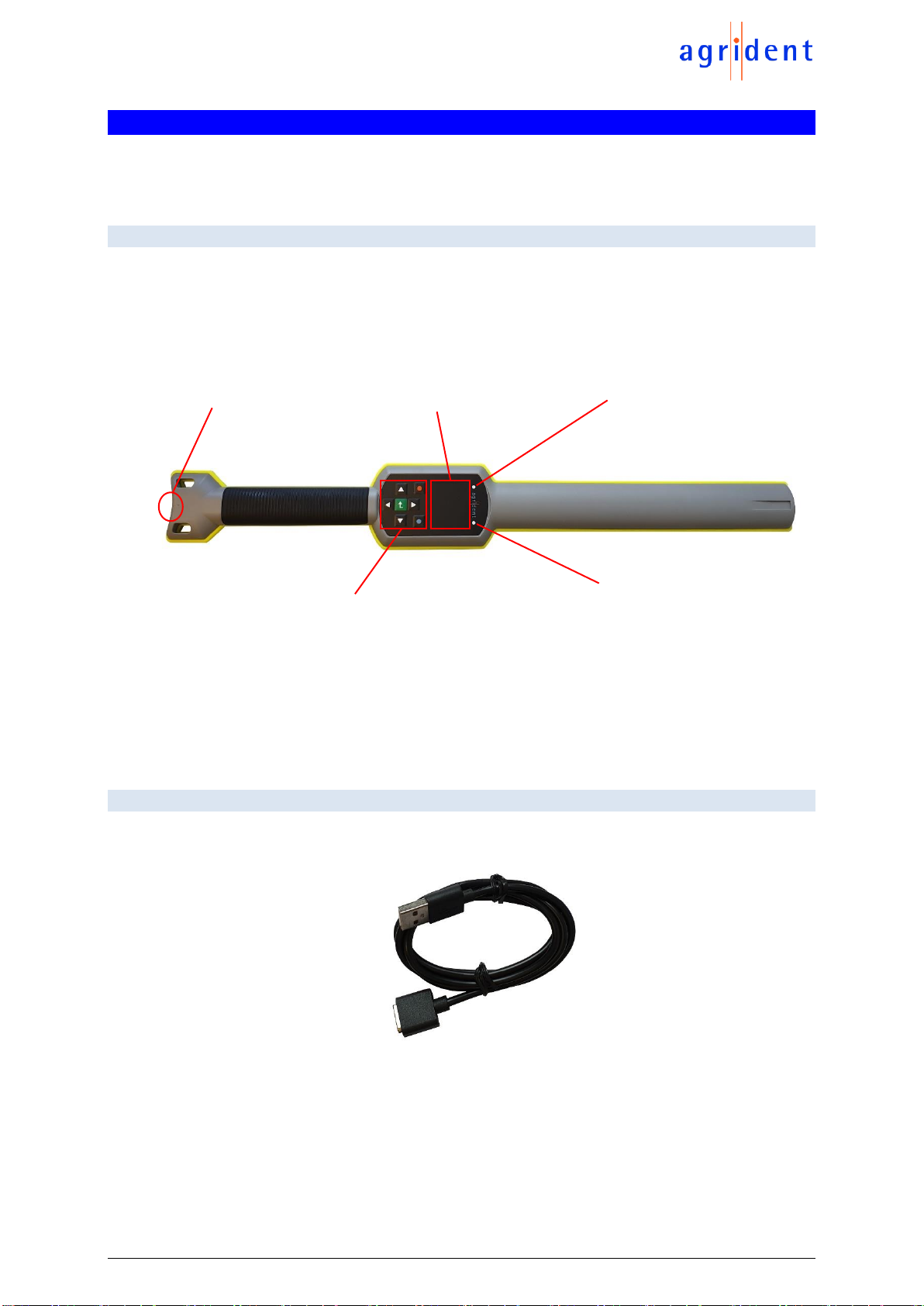
3.1 Parts of the AWR250.................................................................................... 6
3.2 Accessories.................................................................................................. 6
3.3 Connecting the USB cable........................................................................... 7
4Controlling the AWR250...................................................................................... 8
4.1 AWR250 Display.......................................................................................... 8
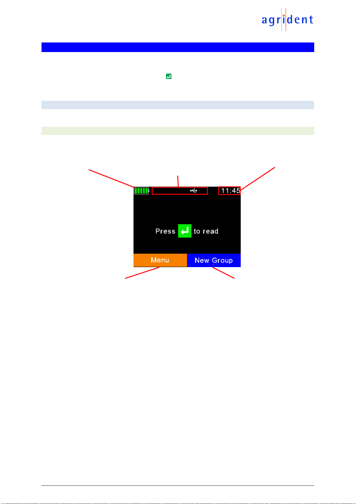
4.1.1 Home Screen........................................................................................ 8
4.1.2 The status symbols at the top of the display ......................................... 9
4.1.2.1 Battery status..................................................................................... 9
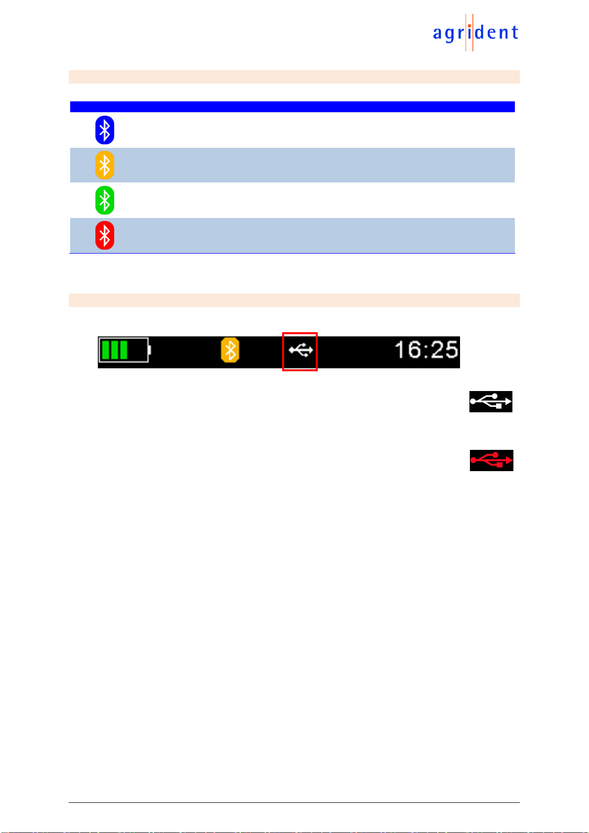
4.1.2.2 Bluetooth status............................................................................... 10
4.1.2.3 USB status....................................................................................... 10
4.2 The status LEDs above the display............................................................ 11
4.3 Using the keyboard .................................................................................... 12
5Operating states................................................................................................ 13
6Reading Transponders...................................................................................... 14
7Menu items........................................................................................................ 17
7.1 Menu structure ........................................................................................... 18
7.2 New Group................................................................................................. 20
7.3 Tasks.......................................................................................................... 21
7.4 Data............................................................................................................ 23
7.4.1 Show Data........................................................................................... 23
7.4.2 Clear data............................................................................................ 24
7.4.2.1 Clear Groups................................................................................... 25
7.4.2.2 Clear Task Data............................................................................... 25
7.4.3 Memory Info........................................................................................ 25
7.5 Print............................................................................................................ 26
7.5.1 Print Last Group.................................................................................. 26
7.5.2 Select Group....................................................................................... 26
7.5.3 Print All Groups................................................................................... 26
7.5.4 Print Barcode ...................................................................................... 27
7.5.5 Setup Printer....................................................................................... 27
7.5.5.1 Set Printer Type............................................................................... 27
7.5.5.2 Search BT Printer............................................................................ 27

AWR250 User Manual
13/02/20 Page 4 of 45
7.6 Setup.......................................................................................................... 28
7.6.1 Reader Settings .................................................................................. 29
7.6.1.1 Animal Counter On/Off .................................................................... 29
7.6.1.2 Set Read Mode................................................................................ 29
7.6.1.3 Set Online Mode.............................................................................. 30
7.6.1.4 Wireless Sync On/Off ...................................................................... 31
7.6.1.5 Volume & Vibrator ........................................................................... 32
7.6.2 Display ................................................................................................ 32
7.6.2.1 Set Date/Time.................................................................................. 33
7.6.2.2 Set Switch Off Time......................................................................... 33
7.6.2.3 Set Display Colors........................................................................... 33
7.6.2.4 Set Language.................................................................................. 34
7.6.3 Interface Setup.................................................................................... 34
7.6.3.1 Setup Scale..................................................................................... 34
7.6.3.2 Setup Printer.................................................................................... 35
7.6.3.3 Bluetooth ......................................................................................... 35
7.6.4 Configuration....................................................................................... 39
7.6.4.1 Set Factory Configuration................................................................ 39
7.6.5 Device Info.......................................................................................... 39
7.6.5.1 Show Battery Info............................................................................ 40
7.6.5.2 Show Firmware Info......................................................................... 40
7.6.5.3 Show Hardware Info........................................................................ 40
8Battery precautions ........................................................................................... 41
9Safety and care................................................................................................. 42
10 Warranty........................................................................................................ 43
11 International approvals................................................................................... 43
11.1 CE marking ................................................................................................ 43
11.2 FCC and IC digital device limitations.......................................................... 44
12 Trouble shooting............................................................................................ 45

AWR250 User Manual
13/02/20 Page 5 of 45
1 Introduction
The AWR250 is a high quality, ruggedized portable RFID reader for tags complying with the
ISO11784 / 11785 standard. It can read transponders with FDX-B and HDX technology. In
addition to the reading functions, the device can store up to 100.000 records in several groups in
the large internal memory. Each record also contains a timestamp plus a Visual ID and an Alert,
if available. The data are transmitted via both interfaces (USB and Bluetooth) directly after
reading.
The AWR250 also supports the Task-Mode, if the appropriate definitions have been uploaded.
This is usually done by 3rd-party Management Software. The reader does not support the DBF
(Data Base Function) –this is reserved for the AWR300 and the APR600.
The reader has a large color display which can show many information at one glance. Together
with the seven keys it allows the easy and convenient navigation through menus and data. In
addition, the device has status LEDs above the display for indicating charging- and interface
status plus the reading status. The integrated speaker provides acoustical feedback to the user
and the vibrating handle is very useful in noisy environments.
2 Before you start
The internal lithium-ion battery should be fully charged before the first use. The battery can be
charged by using the provided Magnetic-USB cable and any USB power source. Please note that
computers can usually not supply more than 500mA on USB ports, hence charging the AWR250
over a USB port of a computer takes longer than charging it from the Agrident USB power supply.
The internal fast charging takes about 4 hours maximum in case the battery was
empty completely when using the Agrident USB power supply. Please note that
the battery will only be charged within a temperature range of 0°C to 45°C (+32 to
113°F).

AWR250 User Manual
13/02/20 Page 6 of 45
3 Reader Hardware
This chapter describes the AWR250 hardware including all accessories.
3.1 Parts of the AWR250
The AWR250 stick reader is 65 centimeters long and has a weight of only 650 grams. It provides
a good reading performance, a large 2.4 inch color TFT display, two status LEDs above the
display, a speaker and a vibrating handle. The Reader can be controlled with seven ergonomic
keys below the display.
The AWR250 is using a 3.6V Lithium-Ion battery with a capacity of 3.400mAh, which is located in
the handle. It is not replaceable in the field. The battery can be exchanged by authorized technical
staff only, in case it has reached its end of life.
3.2 Accessories
The AWR250 comes with a USB-A to Magnetic-Connector cable.
The USB-A plug can be connected to any USB-port of a computer. Please note that the
appropriate USB driver has to be installed first. When it is necessary to use a USB extension, this
should only be high quality cable and it should not be longer than two meter. The maximum cable
length for USB is five meter and this can already lead to problems in practice (slower charging or
USB failures).
Magnetic-USB connector
7 keys for easily
controlling the Reader
Large 320x240 dots
color TFT display
Blue status LED
Multicolor
status LED

AWR250 User Manual
13/02/20 Page 7 of 45
The following optional accessories are available:
When it is required to take the AWR250
to different sites very often, it makes
sense to purchase the robust transport
box ‘ATB300’(p/n 4063). It can
accommodate the reader and its
accessories plus additional devices like
a mobile printer (not included, has to be
purchased via local distributors).
Transport box ‚ATB300’
For charging the AWR250 from the mains, Agrident offers the optional USB power supply
‘APS500’. The optional car charger ‘ACC500’ allows charging of the AWR250 from a cigarette
lighter socket.
APS500 (p/n 3011)
ACC500 (p/n 4043)
3.3 Connecting the USB cable
The AWR250 uses a Magnetic-USB connector. Because the magnets are polarized, the
connectors 'find' the correct orientation almost automatically. When the magnetic connector of the
cable is moved towards the plug at the bottom of the reader (1), the magnets will attract each
other in the correct orientation (2). In the wrong orientation, the magnets will repel each other.
Please do not try to force a connection when the connector is in the wrong
orientation –this might damage the reader and voids the warranty.
For disconnecting USB, just pull the cable away from the device (3).
(1)
(2)
(3)

AWR250 User Manual
13/02/20 Page 8 of 45
4 Controlling the AWR250
The AWR250 has a large color display and seven keys which are used for controlling the device.
The Reader is activated by pressing the key in the middle of the directional pad.
4.1 AWR250 Display
4.1.1 Home Screen
After the reader is switched on, the following home screen appears:
* A 'Softkey' is a key that performs different functions depending on the associated screen display.
The battery status indicator shows the approximate battery level. In this example the battery is
fully charged. It would also display possible faults concerning the battery, in case charging is not
possible.
In the screenshot above, the only active connection is USB. The reader would also indicate a
Bluetooth connection in this area.
The soft keys have different meanings depending on the current operation. In the home screen,
the left soft key is used for entering the menu and the right one for creating a new group separator.
The ‘new group’ function is only the default action triggered by pressing the right soft key. Other
‘quick menus’ might be configured and uploaded to the reader from the PC and the action to be
started can be changed on the reader by long pressing the right soft key.
Battery status
indicator
Connection status
USB, BT
Current time
Current function of
the left soft-key *
Current function of
the right soft-key *

AWR250 User Manual
13/02/20 Page 9 of 45
4.1.2 The status symbols at the top of the display
There is a status bar in the first display line. Beside the time (on the right side) it provides
information about the battery status and the different interfaces.
The orange symbol is for Bluetooth. The color of this symbol depends on the current connection
status.
4.1.2.1 Battery status
The battery symbol on the left side indicates the approximate battery capacity.
Status
Meaning
Battery capacity is higher than 80 percent.
Capacity is between 60 and 80 percent.
Capacity is between 40 and 60 percent.
Capacity is between 20 and 40 percent (no charger connected -> discharging)
Capacity is between 10 and 20 percent (no charger connected -> discharging)
When flashing, capacity is lower than 11 percent.
Capacity is between 20 and 40 percent (only green when charging).
Capacity is between 10 and 20 percent (only green when charging).
General charging error. There is a condition that prevents charging. Please check
the external power supply. If this error is shown repeatedly, the battery might not
work correctly any longer and should be replaced. This error also occurs, when the
battery should be charged outside the allowed temperature range of 0°C to 45°C.
During charging, the battery symbol is constantly filling from the point of the remaining capacity.
Charging is complete if no bars are flashing anymore. The USB cable can be disconnected in this
case.
The menu item ‘Show Battery Info’ in the ‘Setup’
menu (chapter 7.6.5.1) shows an estimate of the
remaining battery capacity in percent as well as the
estimated remaining operating time in idle mode and
in continuous read mode.
Navigation from the home screen:
1x
1x
1x
1x
2x

AWR250 User Manual
13/02/20 Page 10 of 45
4.1.2.2 Bluetooth status
Status
Meaning
Slave Mode –AWR250 can be connected from other devices
Master Mode –AWR250 is trying to connect to remote device.
Connected (in either Bluetooth Mode)
Bluetooth init: This symbol is displayed when the Bluetooth module is currently
booting, being configured or a Firmware update is in progress.
4.1.2.3 USB status
The USB status is shown in the middle at the top of the display:
When the AWR250 is connected to the USB port of a computer or to a
standard USB power supply, the white USB symbol is shown. Charging the
battery takes longer here compared to using the Agrident USB power supply.
In case the AWR250 is connected to an Agrident USB power supply, the
symbol changes from white to red. In this case fast charging will be used.

AWR250 User Manual
13/02/20 Page 11 of 45
4.2 The status LEDs above the display
The AWR250 has two status LEDs above the display.
The left LED is a multicolor type and is used for
multiple purposes. When the display is switched off, it
indicates the charging status of the battery. During the
activation of the RFID engine it shows the reading
status.
The LED on the right is blue and it is used for indicating
the connection status with the display is switched off.
The RGB LED on the left side indicates the charging status of the battery pack with the display
switched off:
Color
Interval
Meaning
Flashing, every second for 10ms
Battery is being charged
Solid
Battery is fully charged
The multicolor LEDs are only used when the AWR250 is in Suspend-Mode (display is switched
off but the device is connected to USB and hence is being charged). When switched on, the
battery symbol in the display indicates the charging status.
With activated RFID engine, the multicolor LED shows the reading status as follows:
Farbe
Intervall
Bedeutung
Flashing slowly
RF is activated, ready to scan tags
Flashing fast
Tag has been read the first time (new tag)
Flashing fast *
Same tag has been read repeatedly *
* only for continuous reading mode (see chapter 7.6.1.2)
The blue LED on the right side is only used when the display is turned off. Then it indicates the
following operating modes:
Color
Interval
Meaning
Flashing every 3 seconds
AWR250 is in SD-Card-Mode (MSC)
Flashing once a second
AWR250 is in Suspend-Mode (CDC)
RGB
Blue

AWR250 User Manual
13/02/20 Page 12 of 45
4.3 Using the keyboard
The AWR250 has 7 keys in order to allow the easy and convenient operation of the reader. There
is a directional pad with an ENTER key in the middle and there are two additional soft-keys below
the display which change their function depending on the current action.
Key
Operation
Enters the menu in the home screen. Moves up one menu level (‘Back’), other
functions depend on current operation –the current function is always displayed on
the left side in the last display line (above the key).
When in the home screen, the configured ‘quick action’ will be executed. Exits the
menu completely and moves back to the home screen. Other functions depending
on the actual operation are shown in the display on the lower right side.
Switches on the AWR250. Starts a reading attempt from the home screen. Enters
menu items and confirms selections there. Moves to the next field in Task-Mode.
No function in home screen *
Switches off the AWR250 on a long press (>2 seconds) *
No function in home screen *
* The directional keys are also used to navigate within menus (up, down, left and right), for
scrolling through selection lists and for selecting characters in numeric or text input fields.
Left soft-key
Right soft-key
ENTER key
Direction keys

AWR250 User Manual
13/02/20 Page 13 of 45
5 Operating states
The AWR250 has several operating states concerning display status and communication
possibilities over USB. The following chart shows the different states.
When the reader is switched on and it is connected via USB, it works in CDC-Mode. That means
a virtual comport is created on the computer and it is possible to send commands to the device
via a serial port connection.
After the configurable switch-off-time (default = 60 seconds) has elapsed, the reader enters
Suspend-Mode when a USB cable is connected. The display is switched off but communication
is still possible. In this state the blue LED on the right above the display is flashing in cycles of
one second. The device will not enter sleep mode as long as USB is connected and the battery
is still charging. The red LED flashes in intervals of one second, indicating that the battery is being
charged. After the battery has been charged completely, the reader enters sleep mode after a
timeout of 60 seconds.
If the AWR250 is connected to USB while it is switched off, the MSC mode is activated. Then the
reader is attached to the computer as a mass storage device and file transfer is possible. Once
the key is pressed, the device will switch on and use CDC-Mode right away. When pressing
for at least two seconds while USB is connected, the AWR250 will enter SD-Card Mode as well.

AWR250 User Manual
13/02/20 Page 14 of 45
6 Reading Transponders

AWR250 User Manual
13/02/20 Page 15 of 45

AWR250 User Manual
13/02/20 Page 16 of 45
After a tag has been read, the display will show the information as in the following screenshot:
VID –Visual ID
EID –Electronic ID
Name of the current group, here: ‘group 3’
Number of records in the current group, here: ‘15’
Return to home screen
Show more information
If ‘Data’ was pressed, the screen on the left side is shown. It provides information about the EID,
VID (if available), Date and Time of reading and the Alert text (if there is one for this tag).
If or is pressed, the screen on the right side is shown. It indicates the tag type (FDX or HDX)
and displays the so called ‘advanced ISO information’. You can move from one screen to the
other by pressing any of these keys.
If an alert is present for the
transponder just read, the
alert text is displayed
continuously inverting and
an alert sound is played.
The alert can be disarmed
(don’t shown again after
next reading of this tag) or it
can be just skipped.
The Alert can be ‘disarmed’ and would then not be shown again if the tag is read the next time.
When selecting ‘Skip’, the Alert remains activated.

AWR250 User Manual
13/02/20 Page 17 of 45
7 Menu items
In order to enter the AWR250 menu, please press
while in the home screen. In the lower left corner of the
display you can also see the information that a press of
the left soft key will force the device to enter the menu.
This screenshot shows the highest menu level. It only
contains the items ‘New Group’, ‘Data’, ‘Print’ and ‘Setup’.
If another language than the default one has been
selected, the menu items will look different.
The entry ‘Tasks’ does only appear, if Tasks have been
uploaded to the device –otherwise this item will be
hidden. The Task-Mode is another operating mode of the
AWR250 that allows the collection of comprehensive
data. For further information about this operating mode
please contact your local distributor.
For the navigation through the AWR250 menus, all seven keys might be used. The directional
keys have the following functions here:
Key
Operation
Enters the next submenu or performs particular actions in the lowest menu level
Moves up one menu item
Moves down one item
Jumps to first entry in the current menu
Jumps to last item in the actual list
With exception of the lowest menu levels, the left (orange) soft key will force the device to move
one menu level upwards and the right one (blue) will let the reader return to the home screen. In
the lowest submenu the right soft key will cancel the action.

AWR250 User Manual
13/02/20 Page 18 of 45
7.1 Menu structure
The following table shows the menu structure of the AWR250 including submenus and options.
Options or actions are shown in italic and the default values for options are marked with ‘ * ’.
Main Menu
1st sub menu
2nd submenu
3rd submenu
4th submenu
New Group
Start new group
Tasks
Start New Control
Show Memory Info
Choose Another Task
Data
Show Data
Select Group To Show
Clear Data
Clear Groups
Clear Last Group
Select Group
Clear All Groups
Clear Task Data
Select Task
Clear All Task Data
Memory Info
Print
Print Last Group
Select Group
Print All Groups
Print Barcode
Setup Printer
Set Printer Type
1 - Generic Line Printer
2- Able Systems AP 1300
*
3 - Extech APEX 2
4 - Extech APEX 3
5 - Extech APEX 4
6 - Zebra QL220
7 - Zebra QL320
8 - Zebra QL420
9 - Zebra QLn220
10 - Zebra QLn320
11 - Zebra QLn420
12 - Martel MCP
1880/7880
13 - MTP-3
Search BT printer
Setup
Reader Settings
Animal Counter On/Off
Animal Counter ON
Animal Counter OFF *
Set Read Mode
Single Read *
Continuous Read
Auto
Set Online Mode
Online Mode On/off
Online Mode ON *
Online Mode OFF
Set Output Format
ASCII
Byte Structure
Compact Coding
Custom Format
ISO24631
NLIS
Raw data
Short ASCII 15 *
Short ASCII 16
ASCII + SCP
Read If Connected
Read always *
If buffer not full
Wireless Sync On/Off
Wireless Sync. ON
No Sync. *

AWR250 User Manual
13/02/20 Page 19 of 45
Main Menu
1st sub menu
2nd submenu
3rd submenu
4th submenu
Setup
Reader Settings
Volume & Vibrator
Set Volume
0% (OFF)
20%
40%
60% *
80%
100%
Vibrator On/Off
Vibrator ON *
Vibrator OFF
Display
Set Date/Time
[set values manually]
Set Switch Off Time
60 min
30 min
20 min
10 min
5 min
3 min
2 min
90 sec
60 sec *
30 sec
20 sec
10 sec
5 sec
Set Display Colors
Black *
White
Set language
[depends on uploaded
languages]
Interface Setup
Setup Scale
Set Scale Type
1 - Tell *
2 - Iconix FX15
3 - TruTest XR3000
4 - BWT BW(S) & JD-II
5 - Gallagher
6 - Dini Argeo DFWLB
7 - Te Pari Scale
Setup Printer
[same as setup printer
on the previous page]
Bluetooth
Set Bluetooth Mode
Master Mode
Slave Mode
Bluetooth OFF *
Start BT Inquiry
BT Device History
Set BT Profile
SPP *
HID
BLE
HID Smart
Set BT Passkey
[default = ‘1234’]
Show Bluetooth Info
Configuration
Set Factory
Configuration
Device Info
Show Battery Info
Show Firmware Info
Show Hardware Info

AWR250 User Manual
13/02/20 Page 20 of 45
7.2 New Group
In the memory of the AWR250, records are organized in groups. One group can contain up to
10.000 records maximum. A new record is created for every transponder which has been read. If
you do not wish to create new records for duplicate reads, please enable the ‘Animal Counter’ –
then duplicates will not be saved again within one group (see chapter 7.6.1.1)
After ‘New Group’ was selected, the user will be prompted
to insert a group name. At this stage the suggested name
can be accepted by pressing or it can be deleted by
pressing the left soft key character by character. A long
press removes all digits in one step. By pressing or
the device will open a soft keyboard which is shown in the
display…
The user can navigate to letters, numbers or symbols and
paste the desired character into the group name by using
the key . By pressing the left soft key the keyboard
content can be switched (capitals & special characters).
After the new group name has been entered completely,
press the right soft key (here: ‘close’) in order to exit the
soft keyboard. Now the name can be checked again and
it will be confirmed by pressing . All transponders read
from now on will be saved in this group (max. 10.000).
After 10.000 records within one group the device will force the user to create a
new group –even if groups are not required for a particular application. But this
only means one press of one key in the simplest case (confirm suggested group
name by pressing ).
If no group has been created manually before the first transponder was read, the
device will insert a group with the default name ‘Group 1’ automatically. If the
name of the first group should be different, the user must insert a group before
scanning for transponders.
Table of contents