AHT ATHEN Series User manual

BEIBLATT
SUPPLEMENT
Gewerbliches Kühl-/Gefriergerät
Commercial refrigeration equipment
Elektronischer Regler CAREL
Electronic controller CAREL
Snr. 386460
Version 1
Status 0818
Copyright © AHT Cooling Systems GmbH. Alle Rechte vorbehalten.
Copyright © AHT Cooling Systems GmbH. All Rights Reserved.

de | AHT Cooling Systems GmbH 386460 Beiblatt Elektronischer Regler CAREL |
386460_1_0818 3 / 14
386460 Beiblatt Elektronischer Regler CAREL
Beiblatt Elektronischer Regler CAREL SNr. 386460
zu Betriebsanleitung
– SNr. 361929 Gewerbliches Kühl-/Gefriergerät
1 Gerätemodelle-Übersicht
Gewerbliches Kühl-/Gefriergerät
Modell Typ R-290 Außenabmessungen [mm]
Länge x Tiefe x Höhe
Maximales Gesamtgewicht
Gerät * [kg]
ATHEN
ATHEN 175 B 842N
B 872N 1 752 x 853 x 910 145
ATHEN 210 B 844N
B 874N 2 102 x 853 x 910 165
ATHEN XL 175
B 843N
B 853N
B 873N
1 752 x 993 x 910 150
ATHEN XL 207
B 746BN
B 846(B)N
B 856N
B 876N
2 080 x 994 x 910 195
ATHEN XL 210
B 745BN
B 845(B)N
B 855N
B 875N
2 102 x 993 x 910 165
ATHEN XL 250 B 840N 2 502 x 993 x 910 185
IBIZA
IBIZA 100 B 739BN
B 839(B)N 1 000 x 851 x 925 95
IBIZA 145 B 739BN
B 839(B)N 1 456 x 851 x 925 115
IBIZA 210 B 739BN
B 839(B)N 2 100 x 851 x 925 155
MACAO
MACAO 100 B 739BN
B 839(B)N 1 000 x 851 x 925 115
MACAO 145 B 739BN
B 839(B)N 1 456 x 851 x 925 140
MACAO 210 B 739BN
B 839(B)N 2 100 x 851 x 925 185
MALTA
MALTA 145
B 722(B)(M)N
B 822(B)(M)N
B 862N
1 456 x 855 x 833 125
MALTA 185
B 728(B)(M)N
B 828(B)(M)N
B 868N
1 851 x 855 x 833 150
MANHATTAN
MANHATTAN 175
B 749BN
B 849(B)N
B 879N
1 753 x 995 x 910 150
MANHATTAN 210
B 747BN
B 847(B)N
B 877N
2 103 x 995 x 910 165
MIAMI
MIAMI 145 B 793BN
B 893(B)N 1 457 x 854 x 833 115

2 | Elektronischer Regler CAREL AHT Cooling Systems GmbH | de
4 / 14 386460_1_0818
Modell Typ R-290 Außenabmessungen [mm]
Länge x Tiefe x Höhe
Maximales Gesamtgewicht
Gerät * [kg]
MIAMI 185 B 794BN
B 894(B)N 1 850 x 994 x 834 145
MIAMI 210 B 795BN
B 895(B)N 2 102 x 854 x 833 160
MIAMI 250 B 796BN
B 896(B)N 2 502 x 854 x 833 180
PALMA
PALMA 185 B 821N 1 851 x 853 x 833 150
PARIS
PARIS 145 B 723BN
B 823(B)N 1 457 x 853 x 833 110
PARIS 175 B 824N 1 752 x 853 x 833 130
PARIS 180 B 824N 1 799 x 853 x 833 135
PARIS 185
B 727(B)(M)N
B 824N
B 827(B)(M)N
B 864N
1 854 x 853 x 833 140
PARIS 210 B 725(B)(M)N
B 825(B)(M)N 2 102 x 853 x 833 160
PARIS 250 B 726BN
B 826(B)N 2 502 x 853 x 833 175
SINGAPORE
SINGAPORE 145 B 851N 1 457 x 853 x 910 100
SINGAPORE 185 B 841N
B 871N 1 850 x 993 x 911 165
SINGAPORE 210 B 844N
B 874N 2 102 x 853 x 910 170
SINGAPORE 250 B 850N
B 870N 2 502 x 853 x 910 180
SYDNEY
SYDNEY 175 B 750BN
B 922N 1 752 x 993 x 910 180
SYDNEY 213 B 751BN
B 924N 2 132 x 993 x 860 175
SYDNEY 223 B 751BN
B 924N 2 232 x 993 x 860 180
SYDNEY 230 B 752BN
B 925N 2 302 x 993 x 910 205
SYDNEY 250 B 753BN
B 926N 2 502 x 993 x 910 215
SYDNEY XL 175 B 754BN
B 927N 1 752 x 1 043 x 910 160
SYDNEY XL 210 B 755BN
B 928N 2 102 x 1 043 x 910 205
SYDNEY XL 250 B 756BN
B 929N 2 502 x 1 043 x 910 225
*Ausführungsspezifische Abweichungen möglich. Genaue Angaben entnehmen Sie den Frachtpa-
pieren. Diese müssen beim Betreiber aufliegen.
Technische Änderungen vorbehalten.
2 Elektronischer Regler CAREL
Als Bedienungselemente stehen Tasten zur Verfügung, die folgendermaßen belegt sind:

de | AHT Cooling Systems GmbH Elektronischer Regler CAREL | 2
386460_1_0818 5 / 14
Abb.1: Bedienungselemente und Displayanzeigen
Bedienungselement Funktion
Zugang Programmierebene
Applikationswechsel (A1-A4)
Alarm quittieren
Sollwerteinstellung
Halbautomatische Abtauung
Kühlfunktion ein- und ausschalten
Sollwert erhöhen
Busadresse erhöhen
Busadresse verringern
Sollwert verringern
1
Abb.2: Displayanzeigen
Displayanzeige (Nr./Symbol) Bedeutung Displayanzeige
1 Ist-Temperatur
Kompressor/Kühlfunktion aktiv
blinkt Alarm Kompressor/Kühlfunktion
Verdampfer-Lüfter aktiv (nur bei Applikation A3)
Abtauung aktiv
Echtzeituhr aktiv
blinkt Alarm Echtzeituhr
blinkt Alarm
Bedienungselement blinkt Alarm
2.1 Kühlfunktion ein- und ausschalten
Die Kühlfunktion nur für Reinigungszwecke ausschalten.
Kühlfunktion ausschalten (Abtauen
von Hand starten):
mind. 3 s drücken.
„OFF“ und die Ist-Temperatur werden abwechselnd am
Display angezeigt.

2 | Elektronischer Regler CAREL AHT Cooling Systems GmbH | de
6 / 14 386460_1_0818
Kühlfunktion einschalten
(Normalbetrieb):
mind. 3 s drücken.
Die Ist-Temperatur und die Symbole werden am
Display angezeigt. Bei Auswahl der Applikation A3 wird
zusätzlich das Symbol am Display angezeigt.
2.2 Sollwert (optional)
Sollwert anzeigen
Eingestellten Sollwert (Temperatur)
anzeigen: 1 s drücken.
Sollwertanzeige verlassen: nochmals drücken.
Sollwert ändern
Eingestellten Sollwert (Temperatur)
anzeigen: 1 s drücken.
Sollwert erhöhen: drücken.
Sollwert verringern: drücken.
Neue Eingabe übernehmen: drücken.
2.3 Applikation auswählen
Es können folgende Applikationen (kundenspezifische Freigabe) ausgewählt werden:
– A1, A2, A3, A4
Technische Daten siehe →Technische Daten
Programmierebene
erreichen: 5 s drücken.
„PS“ und danach „0“ werden am Display angezeigt.
Passwort eingeben: drücken bis „32“ erscheint.
Passwort bestätigen: kurz drücken.
„PrG“ wird am Display angezeigt.
Applikation auswählen:
für circa 12 s drücken (Displayanzeige verschwindet
währenddessen kurzzeitig).
„bn0“ wird am Display angezeigt.
oder drücken bis die gewünschte Applikation erscheint:
bn1 = A1
bn2 = A2
bn3 = A3
bn4 = A4
Neue Eingabe
übernehmen:
kurz drücken.
„Std“ und weitere Statusmeldungen werden am Display angezeigt.
Die IST-Temperatur wird wieder am Display angezeigt.
2.4 Busadresse vergeben
Vor Vergabe der Busadressen müssen die Geräte mit einem entsprechenden Buskabel vernetzt
werden. Beim letzten Gerät muss die Busverkabelung mit einem Abschlusswiderstand beendet
werden.
Die Regler werden standardmäßig mit der Busadresse „1“ (entspricht einem „Stand-alone“- Gerät)
ausgeliefert. Zur Identifikation mehrerer Geräte im Bussystem müssen die Busadressen mit „1“ be-
ginnend vergeben werden.
Busadressen dürfen nicht doppelt vergeben werden. Danach empfehlen wir, die Adressen nach
der tatsächlichen Verdrahtungsreihenfolge einzugeben.

de | AHT Cooling Systems GmbH Elektronischer Regler CAREL | 2
386460_1_0818 7 / 14
Dabei sind max. 207 Adressen möglich.
Busadresse vergeben
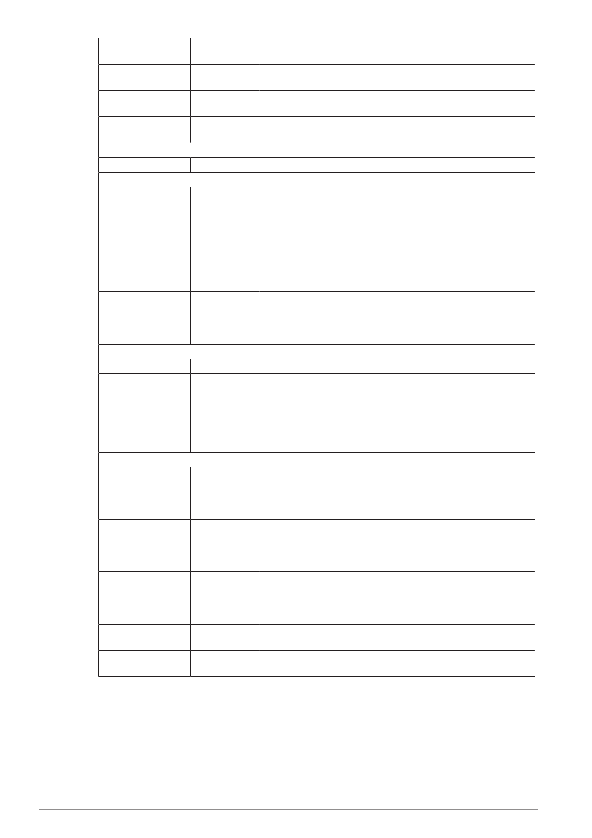
1. – mindestens 3 s drücken.
„PS“ und danach „0“ werden am Display angezeigt.
2. – drücken.
„St“ oder „H0“ werden am Display angezeigt.
3. – oder drücken bis „H0“ erscheint.
Danach drücken.
4. – Höhere Busadresse vergeben: drücken.
– Niedrigere Busadresse vergeben: drücken.
5. – Neue Eingabe übernehmen: einmal drücken.
6. – 5 s drücken.
Die aktuelle Ist-Temperatur wird wieder am Display angezeigt.
Busadresse für nachfolgende Geräte vergeben:
– Punkt 1 bis 6 an jedem Gerät wiederholen und eine freie Busadresse einstellen.
2.5 Halbautomatische Abtauung
Halbautomatische Abtauung starten:
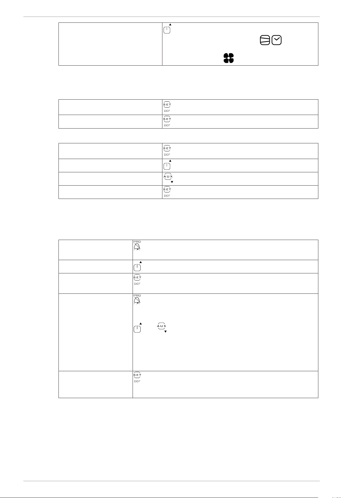
mindestens 5 s drücken.
„dfb“ wird kurz angezeigt. Danach werden „dEF“ und das
Symbol am Display angezeigt.
Nach der halbautomatischen Abtauung kehrt das Gerät automatisch in den Normalbetrieb zurück.
2.6 Alarm anzeigen und quittieren
Alarm anzeigen
Ein Fehlercode wird am Display als blinkende Anzeige abwechselnd mit der Ist-Temperatur ange-
zeigt.
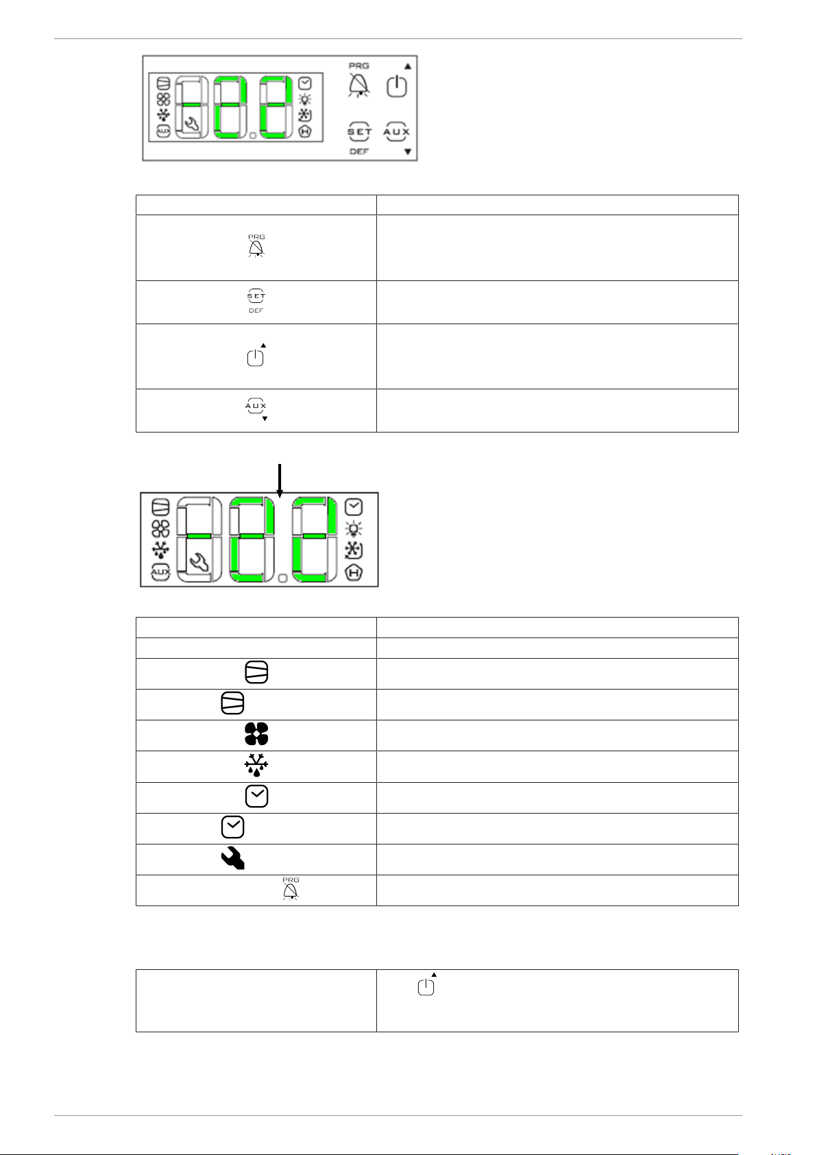
Je nach Fehlerart blinken das Bedienungselement und/oder die Symbole am Dis-
play.
Je nach Fehler wird ein akustischer Alarm durch einen eingebauten Summer ausgegeben.
Auflistung der Fehlercodes:
Fehlercode Bedeutung
E0 Temperaturfühler S1 defekt
E1 Temperaturfühler S2 defekt
E2 Temperaturfühler S3 defekt
LO Niedertemperatur-Alarm
HI Hochtemperatur-Alarm
Etc Echtzeituhrfehler
EE Elektronikfehler
EF Elektronikfehler
CON Verbindungsunterbrechung Inverter zu Regler
Alarm quittieren
Akustischen Alarm quittieren: kurz drücken.
Fehlercode kann NICHT quittiert werden.
Der Fehlercode erscheint abwechselnd mit der Ist-Temperatur so lange bis der Fehler behoben
wurde.
Maßnahmen zur Fehlerbehebung bei Auftreten von Alarmanzeigen siehe →Störung im Betrieb.

| 386460 Supplement Electronic controller CAREL AHT Cooling Systems GmbH | en
8 / 14 386460_1_0818
386460 Supplement Electronic controller
CAREL
Supplement Elektronic contoller CAREL SNr. 386460
to the operating instructions
– Part no.: 361929 Commercial refrigeration appliance
1 Modeltypes-Overview
Commercial refrigeration appliance
Model Type R-290 External dimensions [mm]
Length x Depth x Height
Maximum total weight unit *
[kg]
ATHEN
ATHEN 175 B 842N
B 872N 1 752 x 853 x 910 145
ATHEN 210 B 844N
B 874N 2 102 x 853 x 910 165
ATHEN XL 175
B 843N
B 853N
B 873N
1 752 x 993 x 910 150
ATHEN XL 207
B 746BN
B 846(B)N
B 856N
B 876N
2 080 x 994 x 910 195
ATHEN XL 210
B 745BN
B 845(B)N
B 855N
B 875N
2 102 x 993 x 910 165
ATHEN XL 250 B 840N 2 502 x 993 x 910 185
IBIZA
IBIZA 100 B 739BN
B 839(B)N 1 000 x 851 x 925 95
IBIZA 145 B 739BN
B 839(B)N 1 456 x 851 x 925 115
IBIZA 210 B 739BN
B 839(B)N 2 100 x 851 x 925 155
MACAO
MACAO 100 B 739BN
B 839(B)N 1 000 x 851 x 925 115
MACAO 145 B 739BN
B 839(B)N 1 456 x 851 x 925 140
MACAO 210 B 739BN
B 839(B)N 2 100 x 851 x 925 185
MALTA
MALTA 145
B 722(B)(M)N
B 822(B)(M)N
B 862N
1 456 x 855 x 833 125
MALTA 185
B 728(B)(M)N
B 828(B)(M)N
B 868N
1 851 x 855 x 833 150
MANHATTAN
MANHATTAN 175
B 749BN
B 849(B)N
B 879N
1 753 x 995 x 910 150
MANHATTAN 210
B 747BN
B 847(B)N
B 877N
2 103 x 995 x 910 165
MIAMI

en | AHT Cooling Systems GmbH Electronic controller CAREL | 2
386460_1_0818 9 / 14
Model Type R-290 External dimensions [mm]
Length x Depth x Height
Maximum total weight unit *
[kg]
MIAMI 145 B 793BN
B 893(B)N 1 457 x 854 x 833 115
MIAMI 185 B 794BN
B 894(B)N 1 850 x 994 x 834 145
MIAMI 210 B 795BN
B 895(B)N 2 102 x 854 x 833 160
MIAMI 250 B 796BN
B 896(B)N 2 502 x 854 x 833 180
PALMA
PALMA 185 B 821N 1 851 x 853 x 833 150
PARIS
PARIS 145 B 723BN
B 823(B)N 1 457 x 853 x 833 110
PARIS 175 B 824N 1 752 x 853 x 833 130
PARIS 180 B 824N 1 799 x 853 x 833 135
PARIS 185
B 727(B)(M)N
B 824N
B 827(B)(M)N
B 864N
1 854 x 853 x 833 140
PARIS 210 B 725(B)(M)N
B 825(B)(M)N 2 102 x 853 x 833 160
PARIS 250 B 726BN
B 826(B)N 2 502 x 853 x 833 175
SINGAPORE
SINGAPORE 145 B 851N 1 457 x 853 x 910 100
SINGAPORE 185 B 841N
B 871N 1 850 x 993 x 911 165
SINGAPORE 210 B 844N
B 874N 2 102 x 853 x 910 170
SINGAPORE 250 B 850N
B 870N 2 502 x 853 x 910 180
SYDNEY
SYDNEY 175 B 750BN
B 922N 1 752 x 993 x 910 180
SYDNEY 213 B 751BN
B 924N 2 132 x 993 x 860 175
SYDNEY 223 B 751BN
B 924N 2 232 x 993 x 860 180
SYDNEY 230 B 752BN
B 925N 2 302 x 993 x 910 205
SYDNEY 250 B 753BN
B 926N 2 502 x 993 x 910 215
SYDNEY XL 175 B 754BN
B 927N 1 752 x 1 043 x 910 160
SYDNEY XL 210 B 755BN
B 928N 2 102 x 1 043 x 910 205
SYDNEY XL 250 B 756BN
B 929N 2 502 x 1 043 x 910 225
*Model-specific deviations possible. Exact details can be found in the freight documentation. These
must be available at the operating company.
Technical specifications are subject to change without notice.
2 Electronic controller CAREL
Buttons are available as operating elements, with the following assignments:

2 | Electronic controller CAREL AHT Cooling Systems GmbH | en
10 / 14 386460_1_0818
Fig.1: Operating elements and displays
Operating element Function
Access programming level
Application change (A1-A4)
Acknowledge alarm
Setpoint setting
Semi-automatic defrost
Switch the cooling function on and off
Increase setpoint
Increase bus address
Decrease bus address
Decrease setpoint
1
Fig.2: Displays
Displays (nr./symbol) Meaning displays
1 Current temperature
Compressor/cooling function active
flashes Alarm compressor/cooling function
Internal fan active (only for application A3)
Defrost active
Real time clock active
flashes Alarm real time clock
flashes Alarm
Operating element flashes Alarm
2.1 Switch the cooling function on and off
Switch off the cooling function for cleaning purposes only.
Switch off cooling function (start
manual defrost):
Press for at least 3 s.
„OFF“ and the current temperature are shown on the
display.

en | AHT Cooling Systems GmbH Electronic controller CAREL | 2
386460_1_0818 11 / 14
Switch on cooling function (normal
operation):
Press for at least 3 s.
The current temperature and the symbols are
shown on the display. If you select application A3, the
symbol will be shown on the display additionally.
2.2 Setpoint (optional)
Display setpoint
Show set setpoint (temperature): Press 1 s.
Leave setup menu: Press again.
Change setpoint
Show set setpoint (temperature): Press 1 s.
Increase setpoint: Press .
Decrease setpoint: Press .
Assume new setpoint: Press .
2.3 Select application
The following applications (customer-specific release) can be selected:
– A1, A2, A3, A4
For technical data see →Technical data
Access programming level Press 5 s.
„PS“ ad then „0" are shown on the display.
Enter password: Press unitl „32“ appears.
Confirm password: Press briefly.
„PrG“ is shown on the display.
Select application:
Press for about 12 s (display disappears at the same time briefly).
„bn0“ is shown on the display.
Press or until the desired application appears:
bn1 = A1
bn2 = A2
bn3 = A3
bn4 = A4
Assume new entry: Press briefly.
„Std“ and further status messages are shown on the display.
The current temperature is shown on the display again.
2.4 Assign bus address
Before assigning the bus addresses, the units must be equipped with a suitable bus cable. The last
unit must be provided with a terminating resistor.
The controller are delivered with the bus address „1“ (corresponds to a „stand-alone“- unit). For
identification of several units in the bus system, the bus addresses must be assigned starting with
„1“.
Bus addresses must not be assigned twice. Afterwards, we recommend entering the addresses ac-
cording to the actual wiring sequence.
A maximum of 207 addresses are possible.

2 | Electronic controller CAREL AHT Cooling Systems GmbH | en
12 / 14 386460_1_0818
Assign bus address
1. – Press for at least 3 s .
„PS“ and afterwards „0“ are shown on the display.
2. – Press .
„St“ or „H0“ are shown on the display.
3. – Press or until „H0“ appears.
Then press .
4. – Increase bus address: Press .
–Decrease bus address: Press .
5. – Accept new entry: Press once.
6. – Press 5 s.
The current temperature is shown on the display again.
Assign bus address for subsequent units:
– Repeat point 1 to 6 on each unit and set next free bus address.
2.5 Semiautomatic defrost
Start semi-automatic defrost:
Press for at least 5 s.
„dfb“ appears briefly. Then „dEF“ and the symbol is
shown on the display.
After semi-automatic defrost, the unit automatically returns to normal operation.
2.6 Display and acknowledge alarm
Display alarm
The error code is displayed alternately with the current temperature until the fault has been recti-
fied.
Depending on the type of error the control element and / or the symbols are flash-
ing on the display.
Depending on the type of error an acoustic alarm is emitted by a built-in buzzer.
List of error codes:
Error code Meaning
E0 Temperature sensor S1 defective
E1 Temperature sensor S2 defective
E2 Temperature sensor S3 defective
LO Low temperature alarm
HI High temperature alarm
Etc Real time clock fault
EE Elektronic fault
EF Elektronic fault
CON Disconnection inverter to controller
Acknowledge alarm
Acknowledge acoustic alarm: Press briefly.
Error code can NOT be acknowledged.
The error code is displayed alternately with the current temperature until the fault is rectified.
For troubleshooting measures in the event of alarm indications see →Faults in operation.

en | AHT Cooling Systems GmbH Electronic controller CAREL | 2
386460_1_0818 13 / 14

AHT Cooling Systems GmbH (Headquarter)
8786 Rottenmann - Werksgasse 57 - Austria
Tel: +43 3614 2451 0 | Fax: +43 3614 2451 0 | Email: [email protected] | Internet: www.aht.at
AHT Cooling Systems Brasil Ltda.
Rua Onório Bortolato | 1065–Bairro Pedreiras Navegantes – SC - 88375-000 | Brasil
Phone: +55 (0) 11 4702 / 30 99 | Fax: +55 (0) 11 4702 / 71 68 | Email: [email protected]
AHT Cooling Systems (Changshu) Co., Ltd.
215500 Changshu | 88 Yangguang Avenue | Jiangsu Province | P. R. China
Phone: +86 512 5236 7100 | Fax: +86 512 5236 2393 | Email: [email protected]
AHT Cooling Systems USA, Inc.
7058 Weber Blvd. | Ladson, SC 29456 | USA
Phone: +1 (0) 843/767 6855 | Fax: +1 (0) 843/767 6858 | Email: [email protected] | Internet: www.ahtusa.net
386460
This manual suits for next models
48
Table of contents
Languages:
Other AHT Freezer manuals