Ahuja AMX-912 User manual

OPERATION MANUAL
OPERATION MANUAL
PA AUDIO MIXER
AMX-912
Please read this manual thoroughly before making connections and turning on the power.
Following the instructions in this manual will enable you to obtain optimum performance from your new AHUJA PA
Audio Mixer
Please retain this manual for future reference.

2
AMX-912
CAUTION: To reduce the risk of electric shock, do not remove
the top cover. No user serviceable parts inside. Refer servicing to
qualied personnel only.
WARNING: To reduce the risk of re or electrical shock, do not
expose this equipment to rain or moisture.
Detailed Safety Instructions:All the safety instructions in this manual should be read before operating this
equipment.
Retain Instructions:The operation manual should be kept for future reference.
Follow Instructions:All operation and safety instructions should be followed.
Water and Moisture: In order to prevent any re or shock hazard, do not expose this equipment to rain or
moisture.
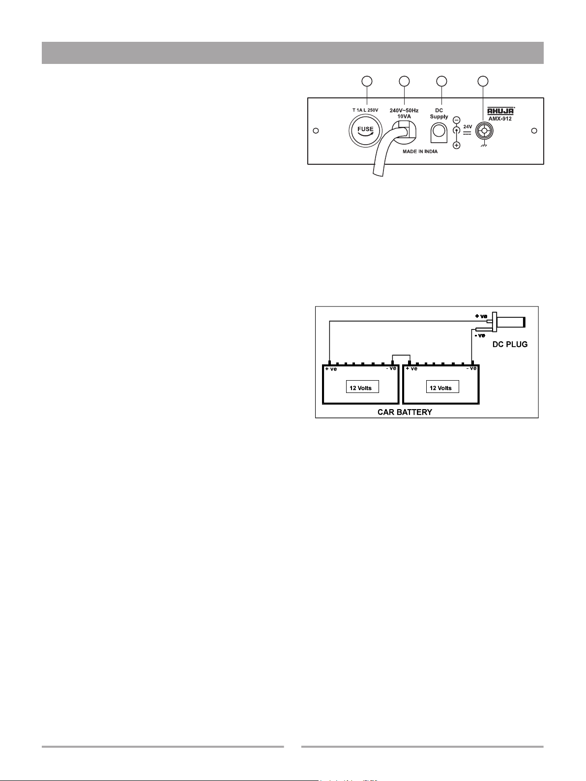
Power Source: The equipment should be connected to a 230V 50Hz AC or 2 × 12V DC power source.
Power-cord Protection: Do not cut, kink, damage or modify the power supply cord supplied with the equipment.
Keep the power supply cord away from heaters & harmful chemicals. Do not place heavy objects on the power cord.
Operation on Generator:When operating the equipment on a generator, make sure it is switched ‘OFF’ till the
generator voltage has stabilized and then only switch the equipment ‘ON’.
Grounding or Earthing:The equipment must be earthed properly before operating it to avoid electric shock. A
wire from the Earth Terminal must be connected to either water pipe or to electrical earth for safe operation.
Replacing AC Mains Fuse: After disconnecting the AC mains and rectifying the defect in the equipment, change
the fuse with another of the specied rating only. Insert and tighten the fuse holder completely to avoid any loose
contact.
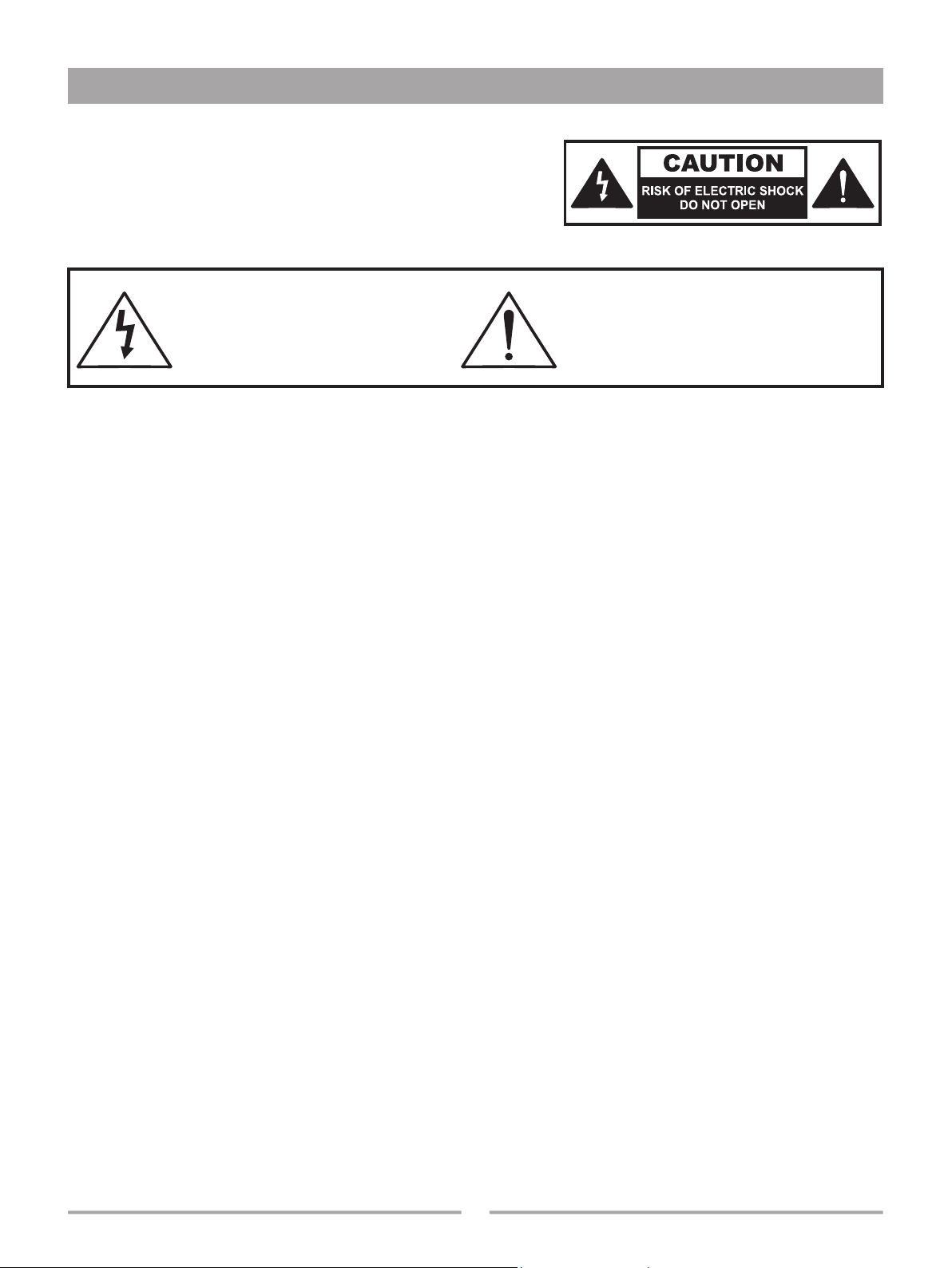
lSafety Instructions
This symbol, wherever it appears, alerts you
to important operating and maintenance
instructions in the accompanying literature.
Read the manual.
This symbol, wherever it appears,
alerts you to the presence of
uninsulated dangerous voltage inside
the enclosure, that may be sufcient to
constitute a risk of shock.

3AMX-912
Contents Page No.
lIntroduction ......................................................................................................................4
lFront and Rear Panel.......................................................................................................5
lThe Input Section.............................................................................................................6
lThe Output Section..........................................................................................................7
lThe Echo Section.............................................................................................................8
lThe Tape Section .............................................................................................................9
lThe Headphone Section ..................................................................................................9
lPower Supply Section....................................................................................................10
lRack Mounting............................................................................................................... 11
lApplications....................................................................................................................12
lOperation .......................................................................................................................14
lPlugs Wiring...................................................................................................................15
l Specications.................................................................................................................16
lTable of Contents

4
AMX-912
The AMX-912 is 9 CHANNEL PA Mixer with Echo, Reverb & Chorus Effects. The 9 Inputs, Mic / Line, have individual
Gain controls, Bass & Treble controls, Echo controls, Pan controls, Channel On/Off switches, Channel faders. It has a
separate TAPE SECTION for Recording and Playback. With a Dual Gain control and On/Off switch for tape playback
provided, effectively this mixer has 11 INPUT CHANNELS.
• 9 Mic inputs for balanced/unbalanced low impedance microphones.
• 9 Line inputs, balanced/unbalanced for connecting CD/Cassette Players,
Keyboards etc.
• Gain controls for each input channel .
• Bass & Treble controls for each input channel.
• Echo mix level controls for each input.
• Pan controls for each input channel for adjusting the routing of the input
channel signal to the Left or Right outputs.
• On/Off switch for each input channel.
• Fader control is provided for each input channel.
• Digital signal processing used for Echo, Reverb and Chorus effects.
• Echo section for Echo , Reverb and Chorus effects through Repeat,
Delay and Level controls. Echo On/Off switch available.
• A separate Tape Section for connecting a Cassette Recorder for recording
/playback.
• Master faders for left and right output .
• High and Low unbalanced Line Outputs provided for the Left and Right
channels.
• Mono/Stereo output switch.
• 10 LED arrays for indicating output levels.
• Headphone stereo output with gain control.
• AC Mains / 24V DC (Car Battery) Operation.
• Standard 19” Rack mounting.
lIntroduction

5AMX-912
lFront & Rear Panel
FRONT PANEL
REAR PANEL

6
AMX-912
1. MIC INPUT
Input through balanced 1/4” phone jacks for accepting both balanced and
unbalanced signals (plugs). For low impedance microphones, 200 ohms to
1K ohms.
Wiring: Tip Hot (+ve phase)
Ring Cold (-ve phase)
Sleeve Ground
2. LINE INPUT
Input through balanced 1/4” phone jacks and accepts both balanced and
unbalanced signals (plugs) from sources such as Cassette Players, CD Players,
Keyboards, Drum Machines etc.
Wiring: Tip Hot (+ve phase)
Ring Cold (-ve phase)
Sleeve Ground
3. GAIN CONTROL
The gain control sets the signal level for the Mic. and Line inputs. The Clip
LED indicates the Max. level of gain control settings.
4. TREBLE CONTROL
The Treble control gives 12 dB of boost or cut at 10 kHz. High boost livens up
a “dead” room acoustics imbalance.
5. BASS CONTROL
The Bass control gives 12 dB of boost or cut at 100Hz. Low cut avoids
boominess in some rooms.
6. ECHO CONTROL
Echo level control is for deciding the level of that channel in the nal Echo Mix.
This is post-Equalizer (Bass & Treble) and post-Fader. Therefore, the level will
be affected by the setting of the Fader.
7. PAN CONTROL
This control routes the channel to either Left or Right Output . Centering the
control positions the signal equally in both the outputs. This is usable when
the mixer output is connected in the Stereo mode. In Mono mode, the setting
of this control is ineffective.
8. ON/OFF SWITCH
This switch is provided for switching OFF of the input channel without disturbing
the control settings.
9. CLIP
The Clip LED lights up when the signal in the channel is approaching overload
(clip) level. Setting this correctly ensures maximum “Signal to Noise ratio”,
that is the best signal level with the minimum amount of background noise. It
should be set just before the overload level. Occasional ashing of the LED
during loud sounds is OK.
10. CHANNEL FADER
The Fader “slider” control determines the output level of the channel in the
overall mix.
lThe Input Section
1
2
3
4
5
6
7
8
9
10

7AMX-912
1. LINE OUTPUT HI
Unbalanced High Line Outputs have been provided for the Left and
Right channels through 1/4” phone jacks. These are for connecting
to the LINE INPUT of the Power Amplier. The Line Output levels
( 0mV to 775mV ) can be adjusted by Master Faders.
Wiring: Tip Signal
Sleeve Ground
2. LINE OUTPUT LO
Unbalanced Low Line Output have been provided for the Left
and Right channels through 1/4” phone jacks. This output is for
connecting to the AUX INPUT of a Monitor/Power Amplier. The
Preampler Output (0mV to 250mV) can be adjusted by Master
Faders. This lower signal output has been given in addition to the
Line Output as many ampliers have only an
Aux Input. This can also be used for connecting to a monitor
amplier while the Line Output is connected to the main power
amplier.
3. LED BARGRAPH
There are 2 colour , 10 segment LED Arrays which display the Left
& Right output levels. The 0dB LEDs correspond to 250mV (LO
Line output) and 775mV (HI Line output ).
4. MONO / STEREO OUTPUT SWITCH
Mono or Stereo Output mode can be selected through this switch.
In case of Mono, the same mixed mono output is available through
any of the Left or Right output jacks. If the Left Output jack is used,
then the signal level can be set by the Left Master Fader. Similarly,
the mono signal from the Right Output jack can be set by the Right
Master Fader.
5. LEFT / RIGHT MASTER FADERS
The Left & Right faders are the master output level controls. These
determine the level of all the signals ( mix ) sent by the Channel
Faders and Tape Playback, to the L/R Line Outputs High and Low
Output jacks.
lThe Output Section
1
2
3
4
5

8
AMX-912
ECHO - Echo Effect is used to repeat the original
sound many times to give multiple voice effect and
is used for vocals. The Control settings for Echo
are as shown in the diag.
REVERB - Reverb is used for giving Hall Effect
to the original sound as repeated reecting sound
raises overall level of the signal. This is also used
for public announcement in Stadia and Open Air
Performances. The Control settings for Reverb are
as shown in the diag.
CHORUS - Chorus Effect is used by a singer to
create an effect as if a Group is performing. The
control settings for Chorus are as shown in the
diag.
The ECHO section provides ECHO, REVERB and CHORUS effects to all the Input channels. These Effects can be
obtained by different settings of Delay Control, Repeat Control and Level Control. The Echo Section can be switched
Off through a On/Off switch.
1. DELAY Control
For setting the time between ECHO repetitions.
2. REPEAT Control
This controls the number of repetitions of ECHO. The higher the
setting, the more repetitions.
3. LEVEL Control
For setting the ECHO level .
4. ECHO ON/OFF Switch
When this switch is in OFF position, AMX-912 operates as Mixer
only without Echo/Effects on all the inputs irrespective of the
settings of the Echo controls of individual channels.
5. PEAK LED
The Echo Controls & Fader Controls of each channel and Level
Control of Echo Section should be set at a level just below the
ickering level of this Peak LED. This LED is for optimizing the
Inputs and Echo levels. The settings of the Channel Faders &
Master Faders have no effect on this LED.
lThe Echo Section
1
2
3
4
5

9AMX-912
A 4 way RCA connector has been provided for connecting a Stereo Cassette Recorder to this audio mixer for Playback
/ Recording. Alternatively, a separate Stereo Cassette Recorder and a Stereo Cassette Player can be simultaneously
connected for Recording and Playback respectively. This facility allows use of the other 9 input channels for connecting
input sources other than a Stereo Cassette Player.
1. RECORDING Outputs
The Left & Right RCA Sockets marked “REC” carry the stereo mix signal
for connecting to the inputs of a stereo cassette recorder for Recording the
program.These can also be connected to the Aux Input of an additional Monitor
/ Power Amplier for driving them. The recording output level from AMX-912
is xed (240mV) and is not affected by the settings of Master Faders and Tape
Gain Controls.
2. PLAYBACK Inputs
The Left & Right RCA Sockets marked “PLAY” are for connecting to the Play
Output of a stereo cassette player or the same cassette recorder being used
for recording. The playback signals are routed to the main stereo mix of
which the level is set by the Master Faders. However, the level of the playback
mix into the main mix is set by the Gain Control. The input sensitivity of the
Playback Inputs is 50mV. It can be adjusted from 50mV to 1V by the Gain
Control to accept input signal from other sources such as a CD Player,
Electronic Keyboard, Drum Machine, Electronic Guitars etc., to this
mixer.
3. PLAY ON/OFF Switch
A Switch has been provided for switching OFF the playback music source
connected to the mixer.
4. PLAY GAIN Control
A Gain Control is provided to set the Level of playback program to the overall program mix.
THE HEADPHONES SECTION
A Stereo Headphone Output is available through a 1/4” stereo jack for
program monitoring.
Wiring: Tip Left Signal
Ring Right Signal
Sleeve Ground
Do not use Headphones of less than 8 Ohms Impedance.
1. GAIN Control
A Dual Gain Control has been provided for setting the level of the
Headphone Output.
2. HEADPHONE Output
An Output has been provided through a 1/4” stereo jack for connecting a
Headphone for monitoring the overall program
lThe Tape Section
1
2
4
3
1
2

10
AMX-912
1. AC FUSE 1 Amps. 250V
This protects the Mixer from damage in case of
excessive current ow. In case the fuse blows,
replace with another one of the same rating.
2. AC MAINS CORD
This is for connecting to AC mains supply. The
Mixer is connected for 230V / 50Hz operation and
will perform satisfactorily even when the AC Mains
voltage drops to 200 V.
3. STANDBY 24V CAR BATTERY OPERATION
2 x 12V Car Batteries can be connected through
the DC Plug (supplied as an accessory) to the DC
Socket as shown in the diag. In case of power
failure, the Mixer continues to operate uninterrupted
through the standby 24V DC Supply. Make sure
the battery polarity is connected correctly.
4. EARTH TERMINAL
Before operating, the Mixer should be grounded
by connecting a wire from this Earth Terminal to a
water pipe or an electrical earth.
l Use 2x12V car batteries exclusively for this
equipment and do not connect any other equip-
ment to these car batteries.
l Connect car batteries only through pre wired
DC plug supplied With this equipment.
l Do not connect negative car. Car battery to
earth terminal.
l This equipment operates on oating 24V DC.
lPower Supply Section
12 3 4

11 AMX-912
The Mixer has been designed for free standing as well as for standard 19” Rack Mounting. The procedure to be
followed for rack mounting is given below.
1. Remove the Top Panel by unscrewing the mounting screws
(8 Nos.) and place the Top Panel on the right side of the
cabinet. The Top Panel can be placed on a Soft Surface (a
cushion or foam piece) to avoid damage to the controls on
the Top Panel.
2. Remove the Power Supply Plate by unscrewing the mounting
screws (2 Nos.) on the Rear Panel. Pull in the Power Supply
Plate with the AC Mains cord.
3. Tilt the Bottom Panel (Cabinet) towards the right side and
remove the Blank Plate from the Bottom Panel by unscrewing
the mounting screws (2 Nos.).
4. Pull out the AC Mains cord attached to the Power Supply Plate
through the opening on the Bottom Panel. Now x the Power
Supply Plate on the Bottom Panel using the mounting screws
(2 Nos.).
5. Fix the Blank Plate on the Rear Panel of the Mixer using the
mounting screws (2 Nos.).
6. Next x the Top Panel back on to the cabinet using the mounting
screws( 8 Nos.).
7. Mount the Mixer on to a rack through the slotted holes on the side anges.
lRack Mounting

12
AMX-912
lApplications

13 AMX-912
lApplications

14
AMX-912
1. Connect the microphones or line input sources like a CD player or Keyboard to the input jacks. Do not connect
both Mic and Line to any one channel simultaneously. Connect the output jacks to the desired equipment. Refer
APPLICATIONS Section, page # 12, 13.
2. Keep all the rotary control settings of the mixer at ‘0’ position.
3. Keep all the Channel Faders at ‘0’ position and the Left/Right Master Faders at minimum position.
4. Keep all the channel ON/OFF switches and Tape Play Switch at OFF positions.
5. Connect the AC Lead of the mixer to the nearest mains socket and connect the battery lead to car battery for
interruption free operation. Refer Power Supply Section, page # 10.
6. Now switch ‘On’ the Mixer and the Input Sources.
7. Switch ‘On’ Channel-1 only, through its Channel On/Off Switch.
8. Connect the Headphones and position the Headphone Gain Control for a comfortable audible level.
9. Increase the Gain Control of Channel-1 only till the Clip LED lights up. Now decrease the gain control so
that the Clip LED just ickers. This is the ideal setting of the gain control.
10. Set the Bass & Treble Controls to the desired levels. Changing the settings of the Bass & Treble Controls may
effect the overall gain. Therefore the Gain Control should be subsequently adjusted to bring the Clip LED to
the correct level.
11. Now move the Slider Fader control of Channel-1 only to position ‘7’.
12. In case Echo Effect is desired on Channel-1 move the Echo Control of Channel-1 to position ‘7’.
13. Switch ‘On’ the Echo Section and set the Echo Section (Delay, Repeat, & Level Controls) for the desired effects.
Refer to the Echo Section for the settings of the Delay, Repeat, & Level Controls, page # 8.
14. Adjust the Pan Control to set the level of the signal in the Left & Right Outputs. Turning the control fully anti-
clockwise will send the signal only to the Left Output of the mixer, and turning it clockwise will send it to the
Right Output.
15. Once Channel-1 is set, do not disturb the control settings of this channel. Then switch ‘Off’ this channel through
the Channel On/Off Switch.
16. Repeat the above procedure for setting the remaining 8 channels.
17. After all the input channels have been set and switched ‘On’, the Peak LED of the Echo Section may start
glowing continuously. Reduce the Echo Control level of individual channels and Echo Section simultaneously
so that the Peak LED of the Echo Section goes below the ickering level.
18. After all the channels are set adjust the individual Channel Faders to obtain the desired MIX at the outputs.
19. Now adjust the Master Faders for desired output levels. However take care that the red LEDs of the LED
Bargraph Array do not glow continuously. Refer Output Section, page # 7.
20. For Recording and Playback refer to the Tape Section, page # 9.
lOperation

15 AMX-912
PLUGS WIRING
The wiring for various jacks (Input & Output Devices) is as shown below:
lOperation

Design and Specications are subject to change without notice owing to continuous product up-gradation. Technical specications are subject to production tolerances.
We cannot be held responsible for printing errors, should they occur. is a registered trademark of Ahuja Radios in India and other countries.
© Copyright Ahuja Radios, 2015. All rights reserved. Any unauthorized reproduction or use of logos, images or design elements is strictly prohibited by law.
No part of this compilation may be reproduced in any manner or translated without written permission.
TRUSOUND PVT. LTD. C-89, Sector IV, Noida, Gautam Budh Nagar-201 301 (UP)
Regd. Ofce : 125E, Okhla Industrial Estate, New Delhi-110 020
Tel.: +91-120-2551452/53 Fax : +91-120-2553677
E-mail: [email protected]
lSpecications
MIC INPUT
Impedance / Gain 2K ohms / 62 dB
LINE INPUT
Impedance / Gain 20K ohms Balanced / 42 dB
10K ohms Unbalanced / 42 dB
THD < 0.08 %
FREQUENCY RESPONSE
L/R Line Output High 30 Hz - 20 KHz (+0, -1 dB)
L/R Line Output Low 30 Hz - 20 KHz (+0, -1 dB)
EQUALIZATION
Bass / Treble ± 12 dB at 100 Hz / 10KHz
CLIP LED INDICATION 4 dB prior to true clip
OUTPUTS
Line Output LO L/R
Nominal / Max. Level -10 dBm / +2 dBm (200mV / 1 V)
Line Output HI L/R
Nominal / Max.Level 0 dBm / +17 dBm (775mV / 5.5 V)
LO/HI Impedance 600 ohms
MAXIMUM GAIN
Mic input to Line Outputs 76 dB
Line input to Line Outputs 55 dB
TAPE
Record Output 240mV RMS / 600 ohms
Playback Input 50mV - 1V RMS/1K ohms,
variable thru’ GAIN control
HEADPHONE
Output 150 mV at 8 ohms, THD < 1%
ECHO
Distortion < 1%
Echo System Digital Signal Processing
Delay Time 20 ms to 600 ms
S / N RATIO
Line Output Level >70 dB (0dBm, 0.775V)
POWER SUPPLY AC: 240V, 50Hz DC: 24V
DIMENSIONS W 483 x H 93 x D 366 mm
WEIGHT 6.75 kg
Table of contents
Other Ahuja Music Mixer manuals