Introduction
①UHF band 490 – 860MHz wireless automatic mixer for a maximum of four wireless microphones.
②Bright and easy-to-read LCD display shows RF/AF, level and other operation status.
③Automatic gain adjustment by microprocessor control.
④5-unit daisy chain by accessory link cable to control up to 20 units microphones.
⑤Select the simultaneous open microphones to 1 unit, 2 units, 3 units or 4 units.
⑥Set the Priority Microphone.
⑦Specific circuitry helps control feedback.
⑧Corresponding various kind of application in conference room due to priority-select function and gate-
hold time setting
⑨Last microphone on selectable for continuous room ambiance.
⑩Microphone hold time for 0.3s to 1.5s.
⑪everal inputs / outputs for audio signals:
wo RCA outputs to realize long distance with low noise transmission.
CA iput / output for recordings.
ne balanced line output (6.3mm jack ).
ne 3-pin XLR.
⑫Two RS-485 interface for external auto video tracking system or auto central control system.
⑬Cooperates with RELACART wireless boundary microphone UB-200, wireless conferncing
microphone ED-3000, handheld microphone UH-200 or lapel microphone UT-200.
⑭The WAM-400 wireless automatic mixer is ideal for meetings, seminars, teleconferencing, house of
worship services, broadcast and conference applications.
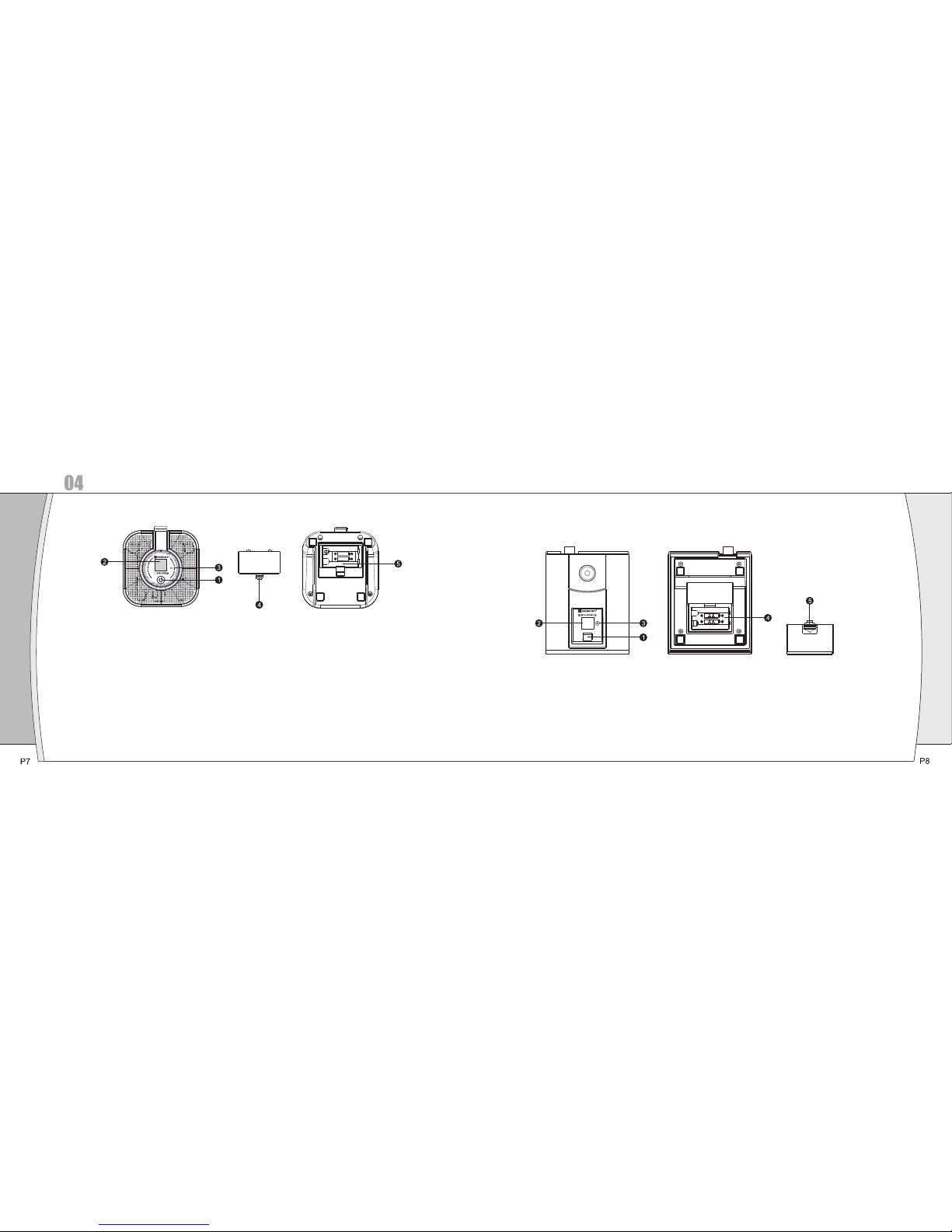
Receiver Installation and Connections
Installation:
①For better operation the receiver should be at least 3ft. (1m) above the ground and at least 3ft.
away from a wall or metal surface to minimize reflections.
②Attached a pair of UHF antennas to the antenna input jacks, the antenna are normally positioned
in the shape of a “V” (both 45°from vertical) for best reception.
③Keep antennas away from noise sources such as computer, digital equipment, motors,
automobiles and neon lights, as well as away from large metal objects.
④Keep open space between the receiver and transmitter for better reception.
⑤The transmitter should be at least 3ft. from the receiver.
Connections:
①The switching power supply is designed to operate properly from any AC power source 100-240V,
50/60Hz without user adjustment. Simply connect the receiver to a standard AC power outlet, using
only an IEC-type input cordset approved for the country use. Power to the unit is controlled by the
front panel power switch.
②There are two audio outputs on the rear panel: an XLR microphone output and a 1/4” (6.3mm)
phone jack instrument output. The two isolated audio outputs permit simultaneous feeds to two
different inputs. Use the appropriate shielded audio cable for connections between the receiver and
the input(s) of the mixer or other equipment.