6
900 1200
kg 180 450
RAL 9010 9010
mm -
RAL 9010 -
mm
mm 2440* 2400
mm 2440* 2500
2. Technical Specications
AM
Weight, Standard unit without panels
Colour, Panel (steel)
Design panel, dimensions 600x500 or 1200x1000
Colour, Case
Dimensions see “Appendix 1 Dimensional Drawings”
Minimum oor-to-ceiling height with wall ducts
Minimum oor-to-ceiling height with roof ducts
* Dimension can be reduced by up to 40 mm when there is no panel and the machine shoes are fully screwed down.
3. Installation
NB! The installation engineer is responsible for
ensuring that the air handling unit is properly secured.
NB! The installation engineer is responsible for
ensuring that any existing functions in the wall/ceiling
(e.g. vapour barrier) are restored and fully functional
once the unit has been installed.
NB! Read this section “Installation” fully before
starting installation!
NB! The walls and oor at the place of installation of
the Airmaster air handling unit must be even and level.
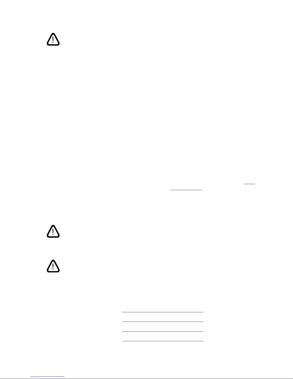
3.1. Positioning of the Unit
The diagram below shows the most important dimensions
relating to the positioning of the unit. (Shown here on an
AM 900).
B
C
A
A: CO2sensor
B: Approximately 1 m
C: Approximately 2 m
NB! The CO2sensor must not be tted close to a window
or door.
NB! Smoke detectors must not be too close to the inlet
and extraction air ow.
NB! For the minimum oor-to-ceiling height for oor-
mounted Airmaster air handling units see section “2.
Technical Specications”.
3.2. Duct Holes
NB! It is recommended that the duct holes be drilled
10-15 mm larger than indicated on the drawings as
this will allow for subsequent insulation, will prevent
direct contact with the wall, and will allow for a vapour
barrier, etc., to be restored.
A rubber diaphragm for restoration of the function
of the vapour barrier is optional available and can be
delivered by Airmaster.
Important! Duct holes in the wall must have an outward
downward gradient of 1-2% to prevent heavy rain
from entering the unit.
1. Marking the holes for the ducts.
Dimensions for duct hole positioning can be found in
“Appendix 1 Dimensional Drawings”
2. Drill duct holes.