Operation, Maintenance and Installation Manual
Alarm Systems Control Panels Float Switches Leak Detection Systems Page 1 of 2
Pump Tracker
PO Box 827 Hawley, MN 56549 (218) 483-3034 Fax (218) 483-3036 www.alderoind.com
Model - 7404
Warning!: Turn off all power when installing or adjusting unit. Failure to turn off all power could result in serious injury or
death! Read instructions thoroughly. Check local codes and install to meet requirements - Refer to National Electrical Code
(NFPA 70).
To connect to a receptacle that is used for a pump and piggy back float switch, refer to Step 1. First, Turn off Power before
wiring. Second, Disconnect the 120 Volt “hot” line from the receptacle and route (may need to splice wire) through the
current sensor and reconnect to the receptacle terminal along with wire from the counter. Connect wire which is white, to
the receptacle “neutral” terminal. Reconnect power. Plug the piggy back pump switch into the outlet and plug the pump into
the piggy back receptacle. When the pump runs, the event counter will activate.
The Event Counter with Current Sensor works by connecting the black and white wires to 120 VAC power source. A “Load”
such as a pump can be monitored by simply running 1 of the “load” lines through the current sensor which is installed on the
side of the event counter. It does not matter which load line runs through the current sensor (either the black or white but
preferably the black). When Current is running through the pump the event counter will increment a count register.
CAUTION! DO NOT CONNECT ANY VOLTAGE OTHER THAN 120 VAC TO THE BLACK AND WHITE WIRES (which is
the control voltage for the counter). A 230 VAC PUMP LOAD MAY BE MONITORED BY RUNNING 1 LOAD LINE
THROUGH THE CURRENT SENSOR, BUT MAKE SURE 120 VAC IS CONNECTED TO THE BLACK AND WHITE WIRES
OF THE EVENT COUNTER.
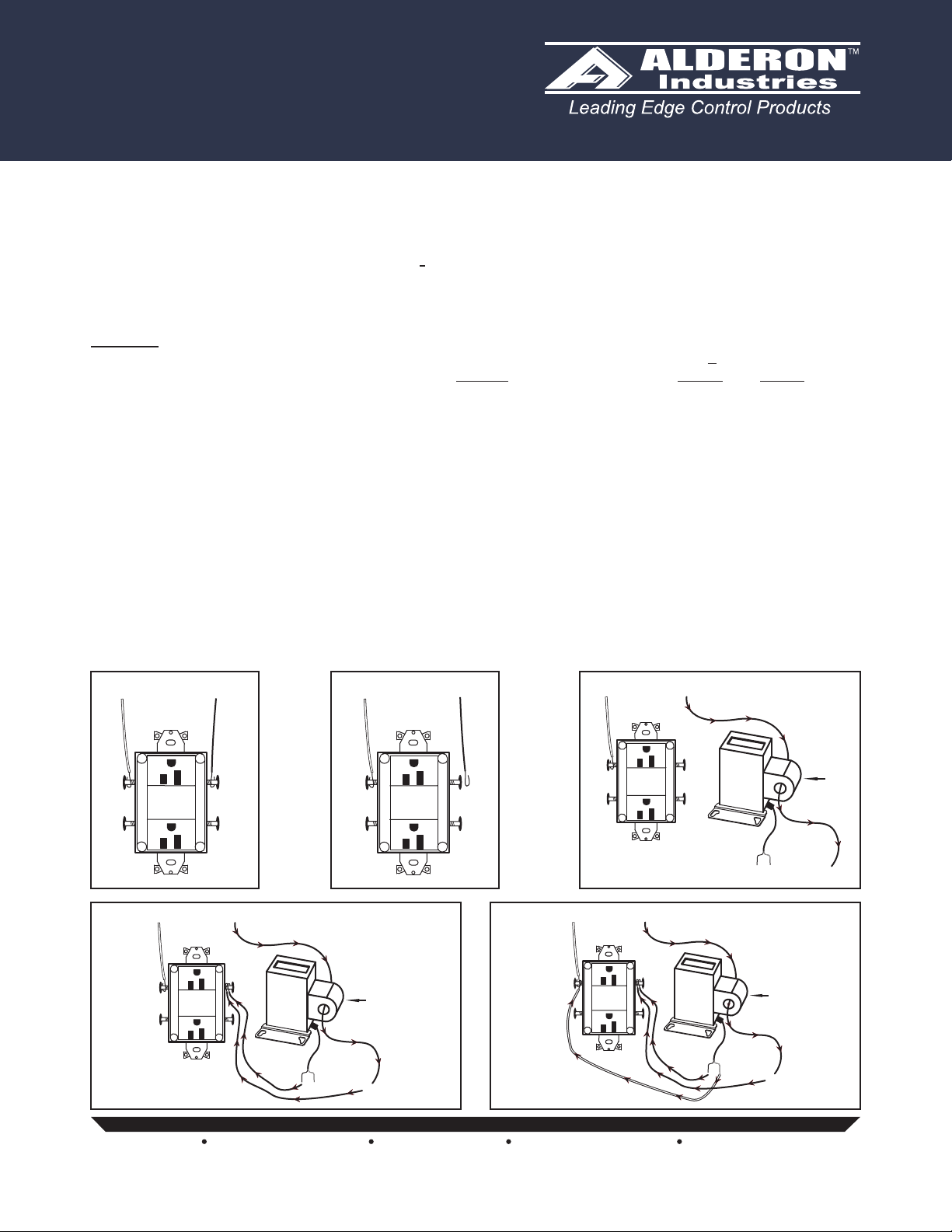
Piggy Back Installation
1. Make sure power is diconnected from the receptacle (Fig. 1).
2. Diconnect the (BLACK) Hot wire from the 120 VAC receptacle (Fig. 2).
3. Pull the (BLACK) Hot wire from the 120 VAC receptacle through the current sensor on the Pump Tracker (Fig. 3).
4. The (BLACK) Hot wire from the Pump Tracker will be wired together with the (BLACK) Hot wire from the 120 VAC
receptacle (Fig. 4).
5. The White wire from the Pump Tracker will be wired together with the White wire from the 120 VAC receptacle (Fig 5).
Receptacle
Power
White Black
WHITE
HOT
WHITE
HOT
120 VAC
60HZ
(Fig. 1)
Receptacle
Power
White Black
WHITE
HOT
WHITE
HOT
120 VAC
60HZ
(Fig. 2)
DISCONNECT POWER
Receptacle
Power
White
WHITE
HOT
WHITE
HOT
120 VAC
60HZ
Black
Black
Black White
Current
Sensor
Pump
Tracker
(Fig. 3)
Receptacle
Power
White
WHITE
HOT
WHITE
HOT
120 VAC
60HZ
Black
Black
Black White
Current
Sensor
Pump
Tracker
(Fig. 4)
Receptacle
Power
White
WHITE
HOT
WHITE
HOT
120 VAC
60HZ
Black
Black
Black White
Current
Sensor
Pump
Tracker
(Fig. 5)


