ALENCON BOSS 1000 User manual

Bidirectional Optimizer for Storage Systems (BOSS)
A unique DC-DC Optimizer to help medium and large
Energy Storage Systems (ESS)
INSTALLATION, OPERATION AND MAINTENANCE MANUAL FOR
USE WITH THE BOSS 1000 AND 1500
PM003 Revision 12
Alencon Systems LLC
330 Warminster Rd., Suite 380 | Hatboro, PA 19040 | USA

BOSS – Installation, Operation and Maintenance Manual
A l e n c o n S y s t e m s L L C - P a g e | 1
© 2009-2019 by Alencon Systems LLC
This document is the confidential and proprietary information of Alencon Systems LLC. No part
of this document may be photocopied, reproduced, stored in a retrieval system, or transmitted in
any form or by any means whether electronic, mechanical, or otherwise without prior written
permission. Alencon Systems LLC reserves the right to change details in this publication
without notice.
Copyright Information: Any product names listed in this manual that are not registered
trademarks of Alencon Systems LLC and/or organization names mentioned may be trademarks
and/or registered trademarks of their respective companies.
Publication Number: PM003
Date and Revision
Revision
ECO Date Author Approval Comment
0 8562 5/29/2019 O.Fishman MM Original Release
1 8563 5/31/2019 P.
Shivshankaran
MM Content Review
2 8564 6/6/19 P.
Shivshankaran
MM Additional Modifications
3 8564 6/7/19 O.Fishman PS Added BOSS Protections
4 8565 10/7/19 P.
Shivshankaran
OSF Hardware + Installation +
PODD
5 8566 10/22/19 P.
Shivshankaran
OSF Added information about
turn_On procedure + test
setups
6 8567 10/23/19 P.Shivshankaran OSF Ground leak Detection +
removal of excess PODD
details. Updated flow
diagram + addition of state
diagram
10 8568 12/13/19 Z. Dereli PS Certification Related
updates are made.
CEC/Peak Efficiency
Updated 12/20/2019
11 8569 1/30/2019 P.Shivshankaran PS Modbus map v.17 added
12 8570 2/3/2020 P.Shivshankaran PS Modbus Map Removed
13 8571 12/16/2020 J. Faber HF Updated with FEED info

BOSS – Installation, Operation and Maintenance Manual
A l e n c o n S y s t e m s L L C - P a g e | 2
Contents
Contents ............................................................................................................................................. 2
General Information ............................................................................................................................ 4
Purpose ..................................................................................................................................... 4
Glossary..................................................................................................................................... 4
Product Warranty ....................................................................................................................... 5
Technical Support and Assistance ............................................................................................. 6
Warnings, Cautions and Notes ................................................................................................... 6
Packing List ............................................................................................................................... 7
Ordering Information .................................................................................................................. 7
IMPORTANT SAFETY INSTRUCTIONS ............................................................................................ 8
Introduction ...................................................................................................................................... 10
Energy Storage Systems Benefits ............................................................................................ 10
Energy Storage Systems Challenges ....................................................................................... 10
Potential Hazards ..................................................................................................................... 10
State-of-Charge and State-of-Health ........................................................................................ 10
BOSS Features ................................................................................................................................ 11
BOSS- Bi-Directional Optimizer for Storage Systems............................................................... 11
Galvanic Isolation ..................................................................................................................... 11
Ground Leak Detection ............................................................................................................ 12
Communication ........................................................................................................................ 12
Parallel Operation .................................................................................................................... 12
BOSS Operation............................................................................................................................... 13
BOSS Controls......................................................................................................................... 13
STATE Machine ....................................................................................................................... 14
Technical Specifications ........................................................................................................... 15
Communication ................................................................................................................................ 16
BOSS Protection .............................................................................................................................. 16
BUS Protection ........................................................................................................................ 16
Under voltage ....................................................................................................................... 16
Current Limit ........................................................................................................................ 16
Short Circuit Protection ........................................................................................................ 16
Battery Protection .................................................................................................................... 16
Under voltage ....................................................................................................................... 16
Over current ......................................................................................................................... 16
Short Circuit Protection ........................................................................................................ 16
Ground Leak Protection ....................................................................................................... 16
Environmental Protection ......................................................................................................... 17
Temperature on Power Semiconductor ................................................................................ 17
Microcomputer Temperature ................................................................................................ 17
Control Board Temperature .................................................................................................. 17
Humidity ............................................................................................................................... 17
BOSS Installation ............................................................................................................................. 18
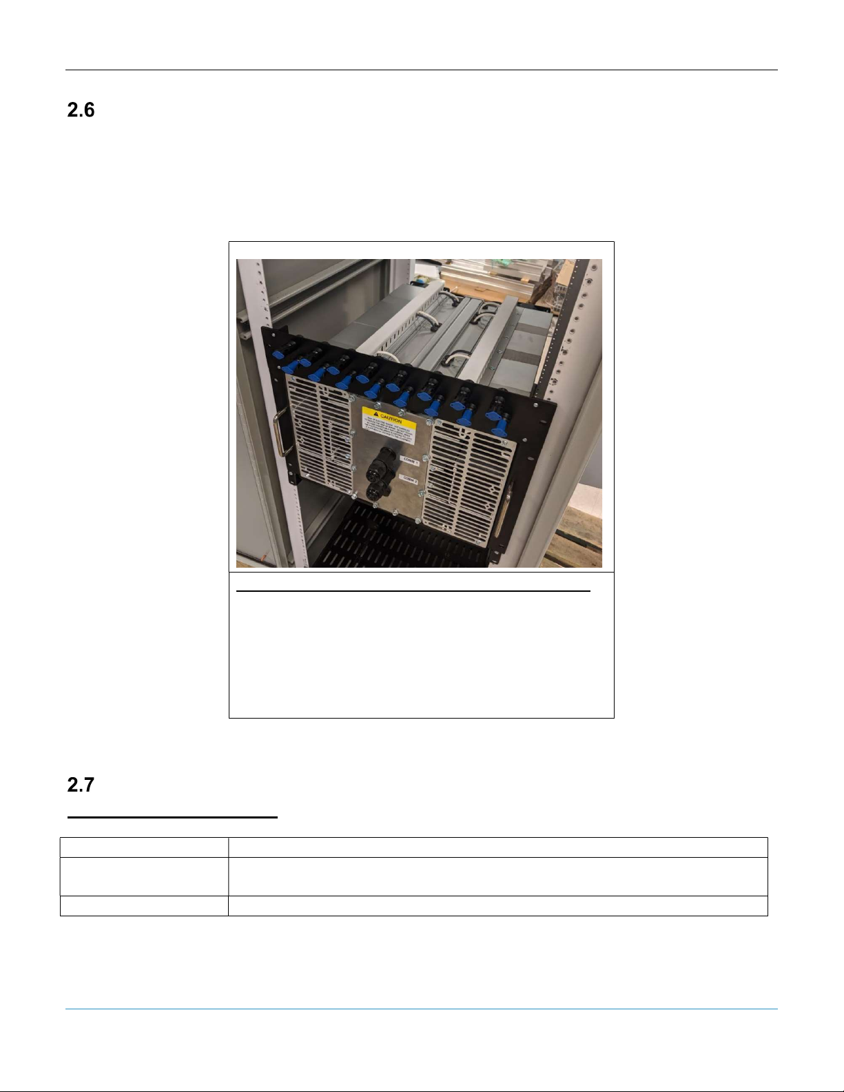
Understanding BOSS Hardware .............................................................................................. 18
BUS & Battery Cable Termination ........................................................................................ 20
Communication Ports ........................................................................................................... 21
Fusing for Input and Output Wiring........................................................................................... 22
Alencon Fused Electrical Disconnect (FEED) ....................................................................... 22
Alencon Communication Environment (ACE) Setup..................................................................... 23
PODD Installation .................................................................................................................... 23
Installation Options ........................................................................................................... 23

BOSS – Installation, Operation and Maintenance Manual
A l e n c o n S y s t e m s L L C - P a g e | 3
Installation Criteria ................................................................................................................... 23
PODD Mounting ....................................................................................................................... 23
PODD Mounting Location ................................................................................................. 23
Mounting Parts ................................................................................................................. 23
PODD Setup .................................................................................................................... 24
Communication Interface – “The HUB” .................................................................................... 25
HUB Features .......................................................................................................................... 25
Alencon Devices Tab ....................................................................................................... 25
Device Commands ........................................................................................................... 25
Config Tab........................................................................................................................ 28
Interfacing with the BOSS ............................................................................................................ 30
Powering the BOSS ................................................................................................................. 30
Soft Pre-Charge of BOSS ........................................................................................................ 32
Testing the BOSS using a DC source and a DC Load.............................................................. 35
Testing the Bi-directional Functionality of the BOSS Using a Single DC Source ...................... 37
Testing the Charge-Discharge Functionality of the BOSS Using Battery Racks .................... 39
Further information....................................................................................................................... 40

BOSS – Installation, Operation and Maintenance Manual
A l e n c o n S y s t e m s L L C - P a g e | 4
General Information
All efforts have been made to ensure the accuracy of material provided in this document at the
time of release. Items are subject to continuous development and improvements. All
specifications and descriptions are subject to change without notice.
Purpose
This manual provides information about installing, operating, maintaining, and troubleshooting
the Alencon’s BOSS PV Harvesting System.
Who Should Read this Manual?
This manual should be read by anyone who needs to:
- Understand the product
- Plan the installation
- Install the product
- Commission the product
- Operate the product
- Maintain the product, if necessary
Glossary
Word
(s)/
Acronyms
Definition
BOSS
Bi
-
directional Optimizer for Storage Systems
SPOT
String Power Optimizer and Transmitter
ACE Alencon Communication Environment – a communication system containing
hardware and software elements provided by Alencon to control power
conversion equipment.
HUB Alencon Communication, Monitoring and Control Software

BOSS – Installation, Operation and Maintenance Manual
A l e n c o n S y s t e m s L L C - P a g e | 5
Product Warranty
Alencon Systems warrants to you, the original purchaser, that each of its products will be free
from defects in materials and workmanship for five years from the date of purchase. Extended
warrantees of an additional five (5), ten (10) and twenty (20) years are also available for
purchase.
This warranty does not apply to any products which have been repaired or altered by persons
other than repair personnel authorized by Alencon System, or which have been subject to
misuse, abuse, accident or improper installation. This warranty does not cover the repair or
replacement of any goods which fail as a result of damage in transit, misuse, neglect, accident,
Act of God, abuse, improper handling, misapplication, modification, improper storage, excessive
stress, faulty or improper installation, testing or repair, negligent maintenance or failure to
comply with the written instructions for installation, testing, use or maintenance (if any) provided
by Alencon Systems. Alencon Systems assumes no liability under the terms of this warranty as a
consequence of such events.
Because of Alencon Systems’ high quality-control standards and rigorous testing, most of our
customers never need to use our warranty service. If an Alencon Systems product is defective, it
will be repaired or replaced at no charge during the warranty period. For out-of-warranty repairs,
you will be billed according to the cost of replacement materials, service time and freight. Please
consult Alencon Systems for more details. If you think you have a defective product, follow these
steps:
1. Collect all the information about the problem encountered. (For example, issues you are
encountering in your PV array or battery system) Note anything abnormal when the
problem occurs.
2. Call Alencon Systems or your licensed Alencon Systems dealer and describe the
problem. Please have your manual, product, and any helpful information readily available.
3. If your product is diagnosed as defective, obtain an RMA (return merchandise
authorization) number from your Alencon Systems. This allows us to process your return
more quickly.
4. Carefully pack the defective product (preferably in the original packaging material it was
shipped in), a fully-completed Repair and Replacement Order Card and a photocopy
proof of purchase date (such as your sales receipt) in a shippable container. A product
returned without proof of the purchase date is not eligible for warranty service.
5. Write the RMA number

BOSS – Installation, Operation and Maintenance Manual
A l e n c o n S y s t e m s L L C - P a g e | 6
Technical Support and Assistance
1. Visit the Alencon Systems web site at www.alenconsystems.com where you can find the
latest information about the product.
2. Contact your distributor, sales representative, or Alencon Systems' customer service
center for technical support if you need additional assistance. Please have the following
information ready before you call:
– Product name, LIN and serial number (see section 6.5 for more information the location
of the LIN and serial number)
– Description of your peripheral attachments including fusing and cables
Warnings, Cautions and Notes
Warning! Warnings indicate conditions, which if not observed, can cause
personal injury!
Caution! Cautions are included to help you avoid damaging hardware or
losing data.
Note! Notes provide optional additional information.

BOSS – Installation, Operation and Maintenance Manual
A l e n c o n S y s t e m s L L C - P a g e | 7
Packing List
Before installation, please ensure the following items have been shipped:
Correct # of BOSS Units specified for your PV System with appropriate mounting hardware
1 x Warranty Card
Bi-Directional Optimizer for Storage Systems
This unit provides a maximum of 4 inputs and 4
outputs.
Figure 1: The BOSS unit
Ordering Information
Model Number Description
Model Number
Description
BOSS-1000-X4 Bidirectional Optimizer for Storage Systems for 600 & 1000V PV
Systems
BOSS
-
1500
-
X4
Bidirectional Optimizer for Storage Systems
for 1500 V Systems

BOSS – Installation, Operation and Maintenance Manual
A l e n c o n S y s t e m s L L C - P a g e | 8
IMPORTANT SAFETY INSTRUCTIONS
WARNING! SAVE THESE INSTRUCTIONS– This manual contains important
instructions for use with the BOSS 600, 1000 and 1500 that shall
be followed during installation and maintenance of these devices.
Figure 2: The graphic above indicates that the BOSS is a grounding conductor.
WARNING! Always ground the BOSS enclosure before energizing the unit.
Use the Ground Lug shown in Figure 3 below on the BOSS to
ground the unit safely.
Figure 3: Ground Lug located on the BOSS Unit

BOSS – Installation, Operation and Maintenance Manual
A l e n c o n S y s t e m s L L C - P a g e | 9
WARNING! A BATTERY CAN PRESENT A RISK OF ELECTRICAL SHOCK,
BURN FROM HIGH SHORT-CIRCUIT CURRENT, FIRE OR
EXPLOSION FROM VENTED GASES. OBSERVE PROPER
PRECAUTIONS.
Figure 4: The graphic above indicates that the BOSS acts as a direct current supply.
Installation of this equipment must be performed by an authorized electrician in
accordance with the local and NEC ANSI/NFPA 70 and OSHA requirements. Follow CSA
C22.1 when installed in Canada.
1. Before installing and using the BOSS, read all instructions presented in this manual and the
cautionary markings shown on the BOSS's enclosure.
2. The BOSS contains no user-serviceable parts. For service and maintenance, the BOSS
should be returned to Alencon Systems LLC or a certified Alencon Systems service center.
3. During operation, hazardous voltages and currents may be present. Only authorized and
qualified personnel should perform servicing/installation.
4. The metallic enclosure surface may become hot during certain operation circumstances.
5. The BOSS 600, 1000 and 1500 requires external fusing. This requirement is explained in
detail in Section 8.2 of this manual “Fusing for Input & Output Wiring”.
6. Test any wire or terminal for the voltage before touching them. Disconnect all input and
output terminals before performing any work on the equipment.
7. Use only accessories recommended or approved by the manufacturer.
8. Ensure that wiring is in good conditions and that all wiring is sized accordingly. Ignoring to do
so may result in a risk of fire.
9. PV modules produce electrical energy when exposed to light and thus can create an
electrical shock hazard. Wiring of the PV modules should only be performed by qualified
personnel.
10. Always have BOSS manual in hand.

BOSS – Installation, Operation and Maintenance Manual
A l e n c o n S y s t e m s L L C - P a g e | 10
Introduction
Energy Storage Systems Benefits
Energy Storage Systems (ESS) is actively advancing into the portfolio of equipment being
offered by the Renewable Energy Industry. In both new and existing PV installations, ESS helps
to overcome intermittency – a major shortcoming of solar and wind as sources of energy. With
ESS, solar power becomes available on demand, just the same as conventional generation
means such as coal and gas. Today, the majority of ESS deployed and being deployed utilize
Lithium Ion battery technology. The cost of batteries has significantly fallen in the past few years
while the need for energy storage capacity has increased due to the increased levels of
renewables on the Grid. These dynamics have made the case for ESS adoption very attractive.
Energy Storage Systems Challenges
Many megawatt-hours of alternative energy can be stored in large containers filled with Lithium
Ion batteries. Individual battery cells are assembled into modules, modules into racks (stacks)
and racks into containers. A large amount of energy is packed in one space and presents a
danger of a potential explosion if conditions of safe charge and discharge are violated or general
deterioration of battery condition is not detected.
Potential Hazards
Each high voltage battery rack has a positive and negative terminal isolated from the battery
case. If all the positive terminals are connected together and all the negative terminals are
connected together then in the case of a short on one of the battery racks, the rest will rapidly
discharge their stored energy into a shorted component causing a huge current reaching tens of
thousands of amperes and risking an explosion. The isolation deterioration of the battery cells to
the grounded case is one of the major factors of fault in the battery rack that may cause fault
current.
State-of-Charge and State-of-Health
The capacity of lithium ion batteries to store and discharge electrical energy is measured in MWh
or KWh. The amount of releasable charge the battery contains at any given time relative to full
capacity of a battery is called State-of-Charge (SOC) and is measured in percentiles:
𝑆𝑂𝐶 =
100%
As batteries age over time as they experience a number of charge/discharge cycles. As such,
their capacity to hold charge diminishes. The degree of degradation of the battery measured as
a percentage of current full capacity to the initial rated capacity is called State-of-Health (SOH)
and is measured in percentiles:
𝑆𝑂𝐻 =
100%
To prevent overcharge of full discharge all battery racks should maintain the same SOC. This
means that charge/discharge current should be controlled according to their SOH.

BOSS – Installation, Operation and Maintenance Manual
A l e n c o n S y s t e m s L L C - P a g e | 11
BOSS Features
BOSS- Bi-Directional Optimizer for Storage Systems
Alencon’s BOSS is an integral part of multi-rack Electrical Storage System (ESS) that increases
the utilization of the battery, extends battery life and improves safety.
Figure 5: ESS with BOSS
The BOSS is comprised of several DC-to-DC converter units (DCDC) that are connected
between a common DC BUS and each individual battery string (rack). Each DC-DC converter
autonomously controls the charge and discharge current into a battery rack.
Galvanic Isolation
The main safety feature of the BOSS is the galvanic isolation incorporated in each DCDC. Due
to galvanic isolation each battery rack is isolated from the DC BUS, the common earth ground,
and from each other up to 2500 VDC potential. This means that in case of a fault in one rack,
the remainder stays completely isolated from the other racks preventing catastrophic fault
currents.

BOSS – Installation, Operation and Maintenance Manual
A l e n c o n S y s t e m s L L C - P a g e | 12
Ground Leak Detection
Many installed PV systems are negatively grounded at the suggestion of the PV panel
manufacturer (though some PV panels do require positive grounding). Additionally, guidance
from the National Electrical Code (NEC) and certain AHJ rulings also encourage PV arrays to be
grounded, as opposed to being allowed to “float.”
By contrast, today’s large-scale battery energy storage systems are generally “floating” or
ungrounded. Alencon’s BOSS leverages the inherent properties of galvanic isolation to provide
the customers with a “Ground leak Detection” feature.
By continuously monitoring the system's differential voltage, BOSS ground-fault detectors can
provide early indication of ground faults before leakage becomes prominent. Galvanic isolation
of each battery rack allows each DCDC to measure the isolation resistance from a positive
battery terminal (BAT 1) and negative battery terminal (BAT2) to the earthed chasses and
compute the leakage current from these terminals.
If the leakage current becomes excessive the ESS may disconnect the DCDC and associated
rack from the system.
Communication
The DC units communicate among themselves and with the ESS controller via an industry
standard MODBUS RTU protocol. (An optional MODBUS TCP-IP is available via PODD
communication controller). The ESS controller collects the SOC and SOH information from the
BMS associated with batteries in the racks as well the power information from the inverter and
DC Bus. Based on this information ESS controller assigns the magnitude of the charge or
discharge current to each DCDC. The purpose is to keep the same SOC on each rack
regardless of its SOH. This way all battery racks can be fully charged and discharged at the
same time, thus assuring full utilization of battery capacity.
Parallel Operation
Each DCDC is designed for a specific maximum current. If a battery rack requires more current
than a DCDC can provide, two or more DCDC may be paralleled. Each DCDC should be
provided with a separate fuse and disconnect. The ESS controller should be programmed to
recognize BOSS configuration.

BOSS – Installation, Operation and Maintenance Manual
A l e n c o n S y s t e m s L L C - P a g e | 13
Figure 6: Parallel connection of DCDC - 2 DCDC’s connected to a single battery rack.
BOSS Operation
The BOSS is packaged in to a 19” rack mounted enclosure for use inside a battery container or
in an IP65 extruded aluminum enclosure for outdoor use. It comprises of four DCDC converter
units, each with its own input and output connections. Alencon provides two types of DCDC
converters: BOSS-1000 rated at 1000 VDC max and BOSS-1500 rated at 1500 VDC max.
Each DCDC generates charge current (from BUS to BATTERY) or discharge current (from
BATTERY to BUS) according to commands it receives from the ESS controller.
BOSS Controls
Each DCDC included in the BOSS has an independent Sic MOSFET full bridge power
inverter/rectifier on the DC BUS side and another Sic MOSFET full bridge power inverter/rectifier
on the Battery side. Both power bridges are linked by a deployment specific, high frequency
transformer. The transformer provides the galvanic isolation as well as mapping of the bus and
battery voltages.
Both power bridges are fully microcomputer controlled. The microcomputer also monitors the
bus voltage and the battery voltage.

BOSS – Installation, Operation and Maintenance Manual
A l e n c o n S y s t e m s L L C - P a g e | 14
The BOSS receives commands like current direction (charge/discharge) and current magnitude
from ESS controller. It DCDC communicates with the ESS controller via MODBUS-RTU.
STATE Machine
DCDC controls operate as a state machine with states:
INITIALIZE
STANDBY
STARTUP
BOOTLOADER
RUN
These states are explained in greater detail in Table 3 of section 7.4 below.

BOSS – Installation, Operation and Maintenance Manual
A l e n c o n S y s t e m s L L C - P a g e | 15
Technical Specifications
Model BOSS 1000 BOSS 1500
Number of DCDCs 4 4
DC Bus Specifications
Max DC Bus Voltage 1000 V DC 1500 V DC
Minimum DC Bus Voltage 200 V DC 200 V DC
Battery Voltage Specifications
Operation Voltage Range - Configurable 360 - 1000 360 - 1500
Individual DC
-
DC
Power and Current
Specifications
Max Current per DCDC @ 25 Deg C Ambient 19.2 A 14 A
Max Power @ 25 Deg C Ambient 19.2 KW 15.4 KW
Max Current per DCDC @ 50 Deg C Ambient 15 A 10 A
Max Power @ 50 Deg C Ambient 15 KW 11 KW
Efficiency
Peak Efficiency 98%
CEC Weighted Efficiency 97.5%
Standards & Compliance
Certifications UL1741, IEC 62109-1, CSA C22.2
Environmental
Storage Temperature -40°C to 60°C
Cooling Forced Air
Humidity 0-95%
Operating Ambient Temp. -40°C to 50°C
Form Factor
Packaging Rack or Rail Mounted, Outdoor Rated
Dimensional Limitations (H x W x D) Rack Mount: 7U - 8U x 19” x 27”/Rail
Mount: 24.8” x 16.5” x 10.6”
Aux Power 24 V Available
Weight Rack Mount: 53 KG/Rail Mount: 51 KG
Communications Modbus RTU Standard/TCP IP optional

BOSS – Installation, Operation and Maintenance Manual
A l e n c o n S y s t e m s L L C - P a g e | 16
Communication
The communication with the BOSS is carried out via MODBUS RTU. Please contact Alencon for Modbus
map information.
BOSS Protection
The BOSS’s protection functions are grouped into three classes:
BUS
Battery
Environment
BUS Protection
Protection caused by conditions on any DC-to-DC converter’s unit. The conditions parameters
are configurable and are stored in the nonvolatile microcomputer memory
Under voltage
The input voltage is too low for normal operation. BOSS enters into STANDBY mode.
Current Limit
Current magnitude is requested by the ESS controller. Current limit is set in the
configuration file and overrides the ESS request.
Short Circuit Protection
When in Discharge mode, Rapid shut down of the DC-to-DC converters unit in case of
external short.
Battery Protection
Under voltage
The output voltage is too low for normal operation. This may prevent upstream equipment
to operate below its designed limit. BOSS enters into STANDBY mode
Over current
Current magnitude is requested by the ESS controller. Current limit is set in the
configuration file and overrides the ESS request.
Short Circuit Protection
When in Discharge mode, Rapid shut down of the DC-to-DC converters unit in case of
external short.
Ground Leak Protection
The BOSS monitors leakage to ground and shuts down if excessive ground leakage
current is detected.
The Ground Leak Monitoring built into the BOSS is not a certified feature, therefore it
does not satisfy the GLDI requiremenets of the overall system. The system must have
an external GFDI device such as GARD (Alencon’s Ground Arc Rapid Disconnect) to

BOSS – Installation, Operation and Maintenance Manual
A l e n c o n S y s t e m s L L C - P a g e | 17
meet the ground fault detection/protection requirements. Please see Alencon’s GARD for
additional information.
Environmental Protection
The BOSS mechanicals are designed to protect it from extreme external conditions of high
temperature and moisture.
Temperature on Power Semiconductor
Monitors the temperature of the Power Semiconductors. Prevents our optimizer from
failure.
Microcomputer Temperature
Monitors the temperature on the Microcomputer. Prevents DC-to-DC converter from
failure.
Control Board Temperature
Monitors the temperature on the PCB. Prevents DC-to-DC converter from failure.
Humidity
Monitors the humidity inside sealed electronic compartment. Prevents DC-to-DC
converter from failure.

BOSS – Installation, Operation and Maintenance Manual
A l e n c o n S y s t e m s L L C - P a g e | 18
BOSS Installation
Understanding BOSS Hardware
The BOSS unit has many different form factors. The form factor is completely dependent on the
application and customer requirement. The possible form factors are –
Rack Mounted
Cabinet
Rail mounted Unit
8U Rack Mounted Unit
Rail Mounted Unit
Cabinet Based Unit for Multiple BOSS units
Figure 7: Different form factors of the BOSS

BOSS – Installation, Operation and Maintenance Manual
A l e n c o n S y s t e m s L L C - P a g e | 19
The most common form factor is the 8U rack mounted BOSS unit as shown below
Figure 8: 8U Rack-mounted BOSS UNIT
The unit has four cooling fans. Ensure that there is enough clearance for the fans to
have sufficient air flow. Follow BOSS Mounting instructions for more info.
To cater to the many different form factors of the BOSS, Alencon offers a few customizable
hardware solutions that will help our customers with installation and integration of the BOSS.
These are hardware elements that will have to be purchase separately from Alencon.
The basic external hardware provided to the customer is –
4 AWG Single Wire Grounding Mechanical Lug
Mounting Plate – if BOSS is going to be hung outside or on a Unistrut
Termination Terminal Block – optional termination scheme
H4/MC4 Solar Connectors – default termination scheme
This manual suits for next models
3
Table of contents
Popular Industrial Electrical manuals by other brands

Beckhoff
Beckhoff KL2784 Documentation

Murata
Murata GRM155R71A224KE01 Series Reference sheet

Murata
Murata GRM31MR72A563KA01 Series Reference sheet

Tyco Electronics
Tyco Electronics BDA installation instructions

Murata
Murata GRM155R62A104ME14 Series Reference sheet

Murata
Murata GQM1555C2D1R0WB01 Series Reference sheet

Murata
Murata GRM21BC81A226ME44 Series Reference sheet

Murata
Murata GJM0335C1E3R0BB01 Series Reference sheet

Murata
Murata GRM319R6YA106KA12 Series Reference sheet

LGL
LGL ECOMPACT2 instruction manual

Murata
Murata GJM0335C1E3R1WB01 Series Reference sheet

Murata
Murata GRM0335C2A8R3DA01 Series Reference sheet