BGK AutoCure 5000 User instructions

January 2016
AutoCure 5000 Portable Repair Arm
Assembly and Operating Manual
AC5-2116-380

2
Contents
Warnings................................................................................................................................................................................. 3
Equipment Safety Guidelines.................................................................................................................................................. 4
Operating Instructions ............................................................................................................................................................ 5
Temperature Controller Single or Double Ramp Operation (See Figure 1)........................................................................ 5
Lamp Installation and Replacement Instructions ................................................................................................................... 7
Heater Position Instructions ................................................................................................................................................... 9
Maintenance ......................................................................................................................................................................... 12
Pivot Points
...................................................................................................................................................................... 12
Lamps, Reflectors and Heat Sensor (Pyrometer) Lens
................................................................................................. 12
Trouble Shooting Guide
...................................................................................................................................................... 13
Heater Power Problems
.................................................................................................................................................. 13
Temperature Controller Problems
................................................................................................................................. 13
Temperature Problems ..................................................................................................................................................... 14
Temperature Controller Error Codes .................................................................................................................................... 15
Ramp/ Soak Errors ............................................................................................................................................................ 15
Service Instructions............................................................................................................................................................... 16
Replacement of new Pyrometer Sensor ........................................................................................................................... 16
Replacement of Pyrometer Controller.............................................................................................................................. 17
Mechanical Drawings and Parts Lists.................................................................................................................................... 19
Pyrometer ......................................................................................................................................................................... 19
Parts Listing - Pyrometer................................................................................................................................................... 25
Heater Head Assembly (ACH5-2116) ................................................................................................................................ 26
AC5 Stand.......................................................................................................................................................................... 30
ACH5-2116 Lamp Wiring Schematic ................................................................................................................................. 45
Spare Parts Recommendations............................................................................................................................................. 46
Warranty ............................................................................................................................................................................... 46
3
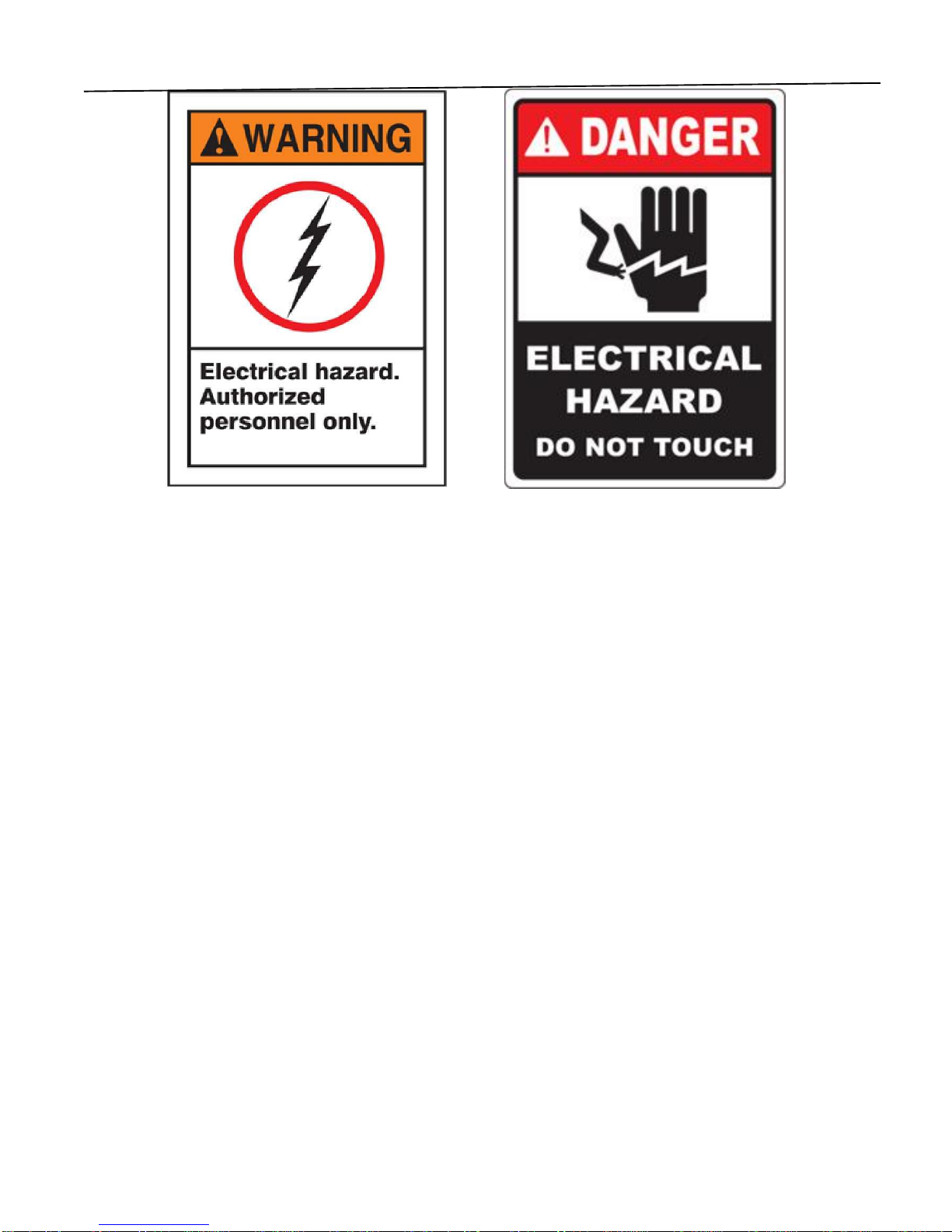
Warnings
DANGEROUS VOLTAGES ARE
PRESENT IN THIS EQUIPMENT!
CONTACT WITH LIVE PARTS
COULD CAUSE
SERIOUS INJURY OR DEATH!
CONNECTION, INSTALLATION, MAINTENANCE,
ADJUSTMENT, SERVICING AND OPERATION TO BE DONE BY
QUALIFIED PERSONNEL ONLY.
ENSURE THAT EQUIPMENT IS COMPLETELY
AND PROPERLY GROUNDED BEFORE APPLYING
SUPPLY POWER AND BEFORE EQUIPMENT
OPERATION.

4
Equipment Safety Guidelines
(Read and understand this manual before operating equipment.)
CAUTION!!
Turn power off at source before servicing equipment or attempting any interior maintenance.
If the main power switch is ON, voltage may exist at the lamps even though the lamps are not lighted. A
FATAL ELECTRICAL SHOCK COULD POSSIBLY RESULT!
This is an automatic piece of equipment. Heater can instantly come on to full intensity without warning to
unaware personnel.
Heater surfaces can become hot when used at high power for extended periods. Use caution
whenever handling heater head.
Do not move heater when in operation.
Heater contains high voltage. Do not insert metallic objects into cooling louver openings.
Ensure that equipment is properly grounded before applying supply power and before equipment
operation.
Use care when positioning heater. Avoid possible pinch points.
LAMPS
All lamp end covers and grills must be installed.
Do not handle infrared lamps with bare hands. Remove any contamination with alcohol and a clean, soft cloth.
Contamination on quartz tubes allows the quartz to overheat, which leads to premature lamp failure.
ENVIRONMENT
Heater head contains high voltage connections that are open to atmosphere. These units are not air-purged.
Ensure use of unit is acceptable in the area in which it will be used.

5
Operating Instructions
Temperature Controller Single or Double Ramp Operation (See Figure 1)
Single Ramp Operation: The temperature ramps in a predetermined amount of time from ambient to a set
point temperature and holds at that temperature for a required amount of time.
Double Ramp Operation: The temperature ramps in a predetermined amount of time from ambient to the first
set point temperature and holds at that temperature for a required amount of time, it then ramps in a
predetermined amount of time to a second set point temperature and holds at that temperature for a required
amount of time.
Temperature Controller Displays
The upper display indicates the mode of the heating cycle and the process temperature. During the Ramp mode
the upper display will toggle between the process temperature and ramping. Once the cure temperature (set
point) has been reached the upper display will toggle between the hold time remaining (in minutes) and the
process temperature. When the hold time becomes less than one minute the upper display will toggle between
the hold time remaining (in seconds) and the process temperature. The lower display indicates the cure
temperature (set point).
Cycle Start Button
The product will heat to the set point temperature and remain there for the time selected. The hold time will
start when the temperature reaches 15°F before set point.
Heater Position
If the heater is too far from the product, the temperature will not be reached and the hold timer will not be
activated.

6
Setting the Temperature Controller Parameters (See Figure 2)
Single Ramp
1. Turn power on.
2. Turn positioning beam on and position heater.
3. Set controller parameters
4. Hold the button for 1-2 seconds
a. Set rp1 (ramp time) in minutes
Press
b. Set ct1 (cure temp) in degrees
Press
c. Set hd1 (hold time) in minutes
Press
d. Set rp2 = 0 (this disables 2nd ramp)
Press
5. Press the to exit setup menu
6. Set auxiliary heater off or on
7. Press the cycle start
Double Ramp
1. Turn power on.
2. Turn positioning beam on and position heater.
3. Set controller parameters
4. Hold the button for 1-2 seconds
a. Set rp1 (ramp time) in minutes
Press
b. Set ct1 (cure temp) in degrees
Press
c. Set hd1 (hold time) in minutes
Press
d. Set rp2 (2nd ramp time) in minutes
Press
e. Set ct2 (2nd cure temp) in degrees
Press
f. Set hd2 (2nd hold time) in minutes
Press
5. Press the to exit the setup menu
6. Set auxiliary heater off or on
7. Press cycle start
Figure 2

7
Lamp Installation and Replacement Instructions
Danger!!
Turn power off at source before removing end covers and servicing lamps. A fatal electrical shock could
possibly result.
Precautions for Handling Quartz Infrared Lamps
Do not handle infrared lamps with bare hands. Remove any contaminations with alcohol and a clean, soft cloth.
Contaminations on quartz tubes cause the quartz to overheat, which may lead to premature lamp failure.
Caution!!
If lamps are replaced with lamps having metal ends, metal ends must be removed to permit proper assembly and
prevent the possibility of arcing or shorting.
Lamp Installation/Replacement Procedure
1. Make sure main system circuit breaker is OFF.
2. Rotate heater so lamps are horizontal.
3. Remove end covers to gain access to lamp leads.
4. Disconnect wire from the ceramic terminal block and remove lamp that is being replaced.
5. Carefully slide the lamp through the lamp support.
6. Remove electrical insulation sleeves from the old lamp on both lamp leads and install them on the new lamp
leads. Push the sleeve to the ceramic end of the lamp (see drawing below).
7. Secure the lamp lead to the power wire coming into the heater at the ceramic terminal block.
8. Install end covers.
NOTE: If lamp leads are too tight, damage to lamp may result.
8
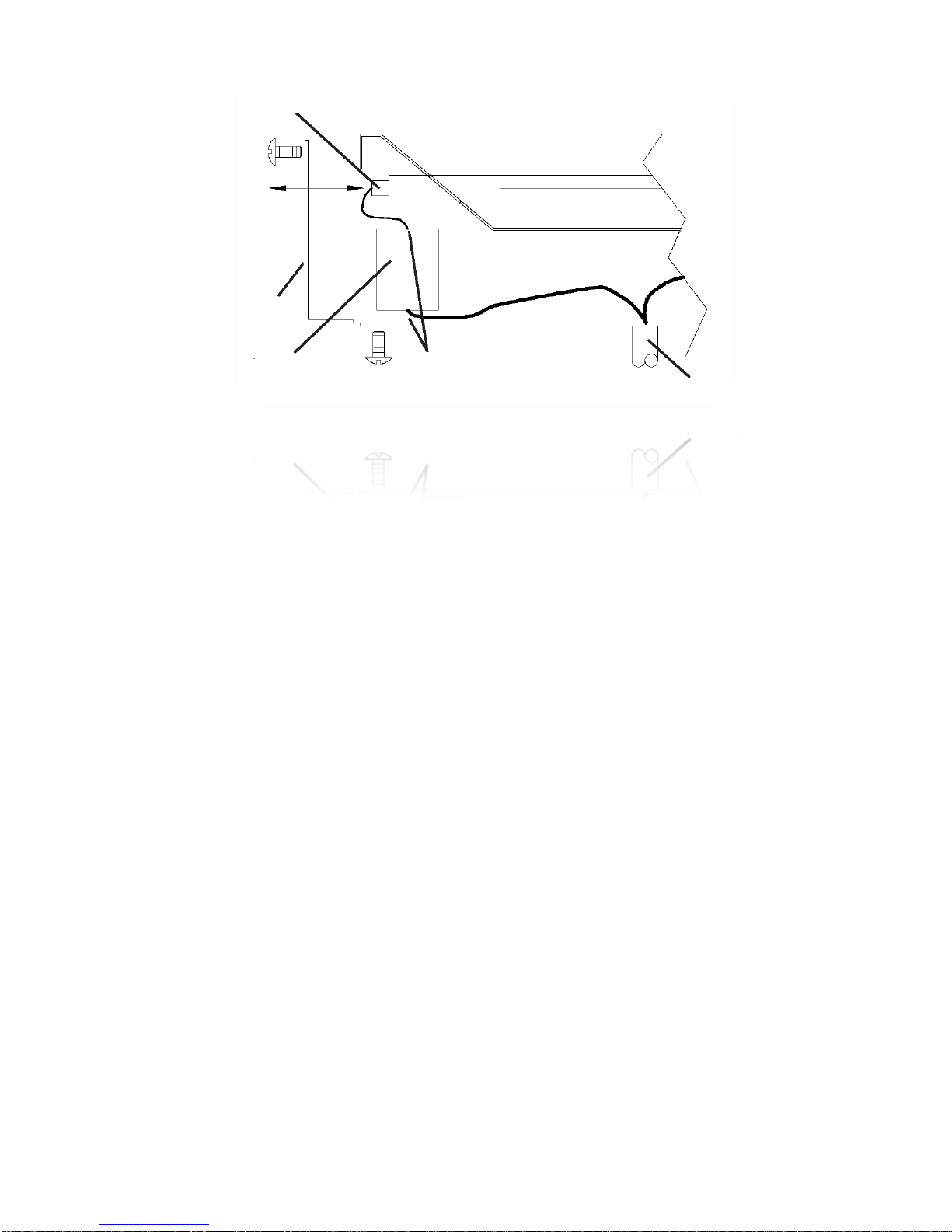
End Cover
Ceramic terminal
in heater head
Ensure all bare wire is
contained up to terminal
(trim lead if necessary)
Heater Power Cord
Make sure lamp sleeving is
pushed all the way into
ceramic end of lamp
Lamp Support
(outer reflector)

9
Heater Position Instructions
Important: Precautions and Instructions
General Instructions (Read All)
1. The "Positioning Beam" (red dot) is an aid for proper placement of the heat sensor. The heat
Sensor reads an area of 0.8 to 1.2" diameter depending on the heater's distance from the
surface. The sensor takes an average temperature reading of the area and displays it on the
temperature controller. Note: the red dot is not at the exact center of the sensing area. As
you face the control panel the dot is 3/4" to the left of the heat sensor.
2. Make sure the heat sensing area is reading a painted surface. If the sensing area is positioned
incorrectly and is partially reading tape, masking, trim, plastic, rubber, a window, or a wheel
well, It will measure an average temperature much higher or lower than the actual temperature
of the painted surface. Thus, the heater will possibly overheat the area and scorch the paint, or
not heat the part enough and the paint will not be cured.
3. The heater head distance from the product is important. If the heater head is too far away, the
product will not reach cure temperature and will run indefinitely trying to get to temperature. If the
heater head is to close "striping" may occur. The recommended distance of the heater face to the
product is 8 -12". The heater should be as parallel as possible to the product surface, which helps
maintain uniform heating over the heated area.
4. Before heating a repair, determine if there are any types of reinforcements or extra thicknesses of
metal in the area to be cured. These areas will heat at different rates and not achieve the same
temperature as the single thickness metals without reinforcements. Aim the heat sensor on, or
near, the multiple thickness or reinforced areas so they will be fully cured.
5. Once the cycle has started, do not move the unit. This will cause the temperature sensor to "see" a
different area, which may be cooler. If the temperature drops 18°F, it will reset the timer and run
another complete cycle. To help the unit's stability, be sure to lock the casters on the base of the
arm after positioning the heater to lock it in place.
6. Check the control panel 3 to 5 minutes into the cycle. See if the temperature has risen to set point
and if the timer has started. If it hasn't, determine the problem and correct it. If there is a problem
with the position or setup of the arm where it cannot achieve the set point temperature, the timer
will not turn on. The heater will run at full intensity indefinitely.
7. To achieve a full cure on a repair area, including overspray, the "effective cure area" of the heater
must be considered. The "effective cure area" of the rectangular shaped heater heads is an oval
shape that is just slightly smaller than the heater head. A general rule for the "effective cure area"
dimensions are 1" in from the sides and end covers of the heater head, which creates the outer
boundaries of the oval. When main and auxiliary heater heads are used together, add the two areas
together.
Heat Masking
1. Any heat sensitive materials or surfaces (including plastic, rubber, trim, pin stripes, decals, light lenses,

10
mirrors, door handles, interior materials, etc.) in the heating area must be masked or removed during
the heating cycle. High temperature/reflective masking material approved for this type of
application is required.
2.
When curing small areas, it is not recommended to use heat masking around the area except to cover
heat sensitive materials. The heat sensor "sees" an area approximately 1" in diameter, a heating area
that is 1.5" or smaller could result in a false reading if the heat sensor is reading the masking.
Positioning/Set-Up of Heater Head Instructions
Positioning/Set-Up of an arm on flat surfaces (doors, hood, roofs, trunk lids, etc.)
1. Follow any of the instructions previously mentioned in the precautions and instructions section.
2. Always position heaters parallel and 8 to 12" from the surface.
3. Aim the positioning beam on spot being repaired; make sure that the beam is not aimed at heat sensitive
materials.
4. Engage caster locks.
5. Recheck heat sensor aim with the positioning beam.
6. Set the temperature and time settings.
7. Start heat cycle.
8. Approximately 3-5 minutes after start, check that the temperature is at set point and the timer has
started.
9. When the timer and the heater lamps shut off, the cycle is complete and ready for the next repair.
Positioning/Set-Up of a heater on a curved or contoured surfaces (fender, hood, roof, trunk corners)
1. Follow any of the instructions previously mentioned in the precautions and instructions section.
2. Always position heaters parallel and 8 to 12" from the surface. Adjust the A and B heaters to the contour
of the curve, with the most direct heat radiation in the area of the repair.
3. Aim the positioning beam on spot being repaired; make sure that the beam is not aimed at heat sensitive
materials.
4. Engage caster lock.
5. Recheck heat sensor aim with the positioning beam.
6. Set the temperature and time settings.
7. Start heat cycle.
8. Approximately 3-5 minutes after start, check that the temperature is at set point and the timer has
started.
9. When the timer and the heater lamps shut off, the cycle is complete and ready for the next repair.

11
Positioning/Set-Up of an arm on roof posts (heavy reinforcements/multiple metal thickness)
1. Follow any of the instructions previously mentioned in the precautions and instructions section.
2. Position heaters parallel to the surface, the length of the heater along the length of the roof post. Do not
put the heater 90° to the post, unless the repair area is very small. The heater should be about 8" from
the surface for the heavy reinforcement in the posts.
3. Aim the positioning beam on spot being repaired; make sure that the beam is not aimed at heat sensitive
materials. The post is very narrow, so carefully position the heat sensor where it will "see" the post.
4. Engage caster lock.
5. Recheck heat sensor aim with the positioning beam.
6. Set the temperature and time settings.
7. Start heat cycle.
8. Approximately 3-5 minutes after start, check that the temperature is at set point and the timer has
started.
9. When the timer and the heater lamps shut off, the cycle is complete and ready for the next repair.
Positioning/Set-Up of an arm on rocker panels (heavy reinforcements/multiple metal thickness)
1. Follow any of the instructions previously mentioned in the precautions and instructions section.
2. Position heaters parallel to the surface, the length of the heater along the length of the rocker panel. If
there is an auxiliary heater head,
use
both heaters and bend them at about a 135° angle to focus more
direct heat around the curve of the rocker panel. The heater should be spaced about 8" from the surface
for the heavy reinforcement in the rocker panel.
3. Aim the positioning beam on spot being repaired; make sure that the beam is not aimed at heat sensitive
materials
4. Engage caster lock.
5. Recheck heat sensor aim with the positioning beam.
6. Set the temperature and time settings.
7. Start heat cycle.
8. Approximately 3-5 minutes after start, check that the temperature is at set point and the timer has
started.
9. When the timer and the heater lamps shut off, the cycle is complete and ready for the next repair.
NOTE: These are procedures that give reliable results for most repairs. Unusual or complex repairs might need
modified procedures. Contact BGK service for assistance.
12
Maintenance
The AutoCure™5000 will require some basic maintenance when used on a regular basis. Failure to do so may
degrade the performance of the unit.
Disconnect main power at the source before performing any maintenance procedures.
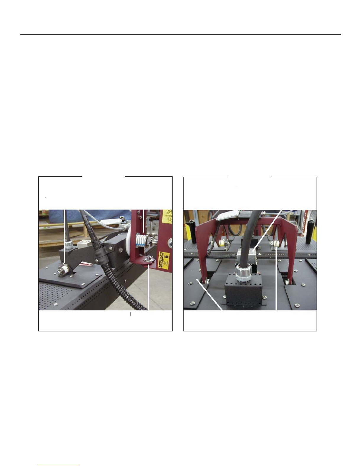
Pivot Points
1. Single head units have three (3) castle nut/spring combinations and two (2) shoulder bolts with Nylock nuts.
If pivot points become loose, heater positioning will not be maintained. Check these points monthly.
2. Dual head units have seven (7) castle nut/spring combinations and two (2) shoulder bolts with Nylock nuts. If
pivot points become loose, heater positioning will not be maintained. Check these points monthly.
3. To adjust spring tension; remove cotter pin, tighten castle nut (usually one or two notches) and replace cotter
pin through bolt.
Lamps, Reflectors and Heat Sensor (Pyrometer) Lens
Clean with soft cloth and alcohol monthly. Heat sensor accuracy is dependent on a clean lens.
Tension Spring/
Castle Nut
NylockNut
Tension Spring/
Castle Nut (4)
(under heater skin)
Tension Spring/
Castle Nut (2)
Tension Spring/
Castle Nut (2)
Single Head
Dual Head
Pyrometer

13
Trouble Shooting Guide
Heater Power Problems
Problem
Heater lamps come on immediately when disconnect is closed.
Possible Cause and Corrective Action
With power OFF, measure the resistance from the lamp wires to ground. The measurement should be
more than 100 K ohms. If it is less than 100 K, check the lamp wiring and heater head for shorts to ground.
Check for a bad firing circuit board or a shorted SCR by: exchanging the firing circuit board with one from
a known good control. Does the problem follow the firing circuit board or does it stay with the SCR –replace
the defective component.
Contactor held closed –failed ON. Replace the contactor.
Problem
Heater lamps do not come on.
Possible Cause and Corrective Action
Is the Power On/Off button illuminated, is the temperature controller on? –Check that
incoming line power is present; transformer fuses, primary and secondary are good.
Do the contactors energize when the Cycle Start button is pressed? –Check for loose wires
associated with the contactors, change the temperature controller.
Check that the set point (bottom display) is higher than the process temperature (top
display).
Are the line fuses (FU 101 & 104) in front of the contactors good –check voltage on the load side of the
fuses or remove the fuses and check with an ohmmeter.
Is the green LED on the firing circuit lit? –Check that the firing circuit has 24 vac, with an ammeter
check that the 4-20ma input signal is present from the temperature controller. If the 4-20ma
signal
is not
present, see the section “No Output Signal from Temperature Controller”.
Do any of the zones function? –If the above points have been checked, confirm that there is a
complete circuit through the lamps and all wiring is tight –change the SCR.
Are all 3 zones dead? –Zone A should function regardless of the zone switch setting, there is only one firing
circuit for all zones - change the firing circuit
Temperature Controller Problems
Problem
Temperature controller has no display.
Possible Cause and Corrective Action
Check the supply voltage (24 VAC) to the unit at terminals 11 and 12. If voltage is present, replace the controller. If
voltage is not present, check source of power (fuses, transformers, wiring, etc.)

14
Problem
No output signal from temperature controller.
Possible Cause and Corrective Action
Check that the set point (bottom display) is higher than the process temperature (top
display).
Check the 0-5v input to the temperature controller at pins 9 & 10. If the 0-5v signal is not
present, confirm that the Raytek pyrometer is functioning.
Open the Raytek cover. Is the LCD display in side, lit? If not check that the Raytek input
power (12 vdc) is present, check that the power supply board is supplying 12 vdc (TB 4). –
replace the temperature controller, Raytek or the power supply board.
Problem
Temperature controller output signal is present, but heater lamps do not come on.
Possible Cause and Corrective Action
Possible defective power controller firing circuit board and/or SCR. Check for a bad firing circuit board or SCR
by exchanging the firing circuit board with one from a known good control. Does the problem follow the firing
circuit board or does it stay with the SCR –replace the defective component.
Temperature Problems
Problem
The heater reaches set-point temperature, but the paint isn’t cured properly or is darkened or the heater does
not reach set-point temperature.
Possible Cause and Corrective Action
Read the instructions in the manual on how to position and run the heater.
Clean the temperature sensor lens as described in maintenance section.
The optical pyrometer is not seeing the surface of the object being heated. The pyrometer
has about a 1-inch diameter field of view on the objects’ surface. Position the heater head
with the pyrometer so it sees the surface being heated. Make sure the pyrometer is not
seeing parts of a window, wheel well, tape, masking, etc.
Problem
The temperature display jumps up or down many degrees within a second.
Possible Cause and Corrective Action

15
Check for loose connections on the heat sensor (pyrometer) wiring.
While the heater is running at temperature, gently wiggle the pyrometer cable and have
someone watch for sudden temperature changes. If this happens –replace the cable.
Problem
Positioning Beam does not work
Possible Cause and Corrective Action
Check that the power supply board is supplying approximately 3.25 vdc (TB 3). Check that the wires are secure
on the power supply board and on the push button. Open the cover on the heat sink assembly on the back of
the heater and retest for the 3.25 v. If the power supply is functioning and there is no voltage at the heat sink
assembly open the Raytek pyrometer and test for the voltage (the 2 wire nuts). –replace the Positioning
Beam.
Temperature Controller Error Codes
Display
Problem
Actions
Err.H
Open Sensor
Check sensor, wiring,
and input
Err.L
Reversed Sensor
Check Sensor polarity
LPbr
Loop Break
Correct problem and
Reset controller
0100
Checksum Error
Press Any Key to
perform a soft reset
and reinitialize
controller
0101
RAM Error
0202
Defaults Loaded
0303
EEPROM Write Failure
3865
Power Fail Resume
Feature Disabled
No further resume
actions available
36 Plus other 2 digit code
Unexpected or invalid
interrupt
Reset Controller
Ramp/ Soak Errors
02= Recipe Empty (i.e. no non-zero ramp times)
05= Insufficient Setpoint- Process Value Deviation
16
Service Instructions
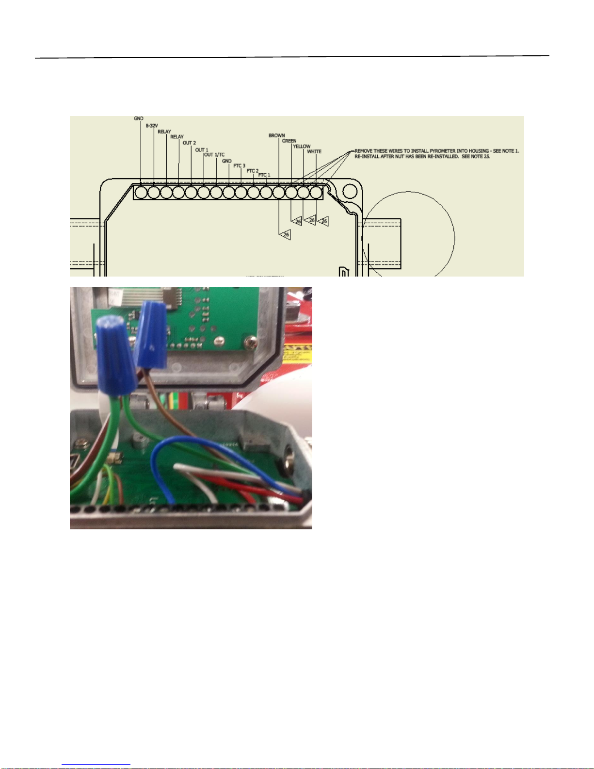
Replacement of new Pyrometer Sensor
1. Open Cover for Raytek Sensor, loosen and remove wire from terminals shown below.
2.
3. Undo wires from two wire nuts, as shown.
4. Loosen nut on pyrometer side, and remove wires from housing.
5. Open enclosure on top of heat sink, and isolate wires for laser (black/ red leads)
6. Clip leads, leaving enough wire to strip and re-connect with crimp connections
7. Loosen and remove standoffs
8. Remove Insulating plate
9. Remove heat sink, then remove Pyrometer.
10. Install new pyrometer into heat sink, making sure to adjust fit using varnish tape wrapped on the outside.
11. Install heat sink onto lower insulators
12. Install intermediate plate
13. Crimp laser leads to leads in pyrometer bundle –red to green and brown to black.
14. Install standoffs
15. Replace cover and tighten nuts.
16. If new pyrometer, replace grommet into side of housing.
17. Reconnect leads in Raytek sensor housing using schematic in Step 1.
18. Reconnect wires in wire harness as shown above.

17
Replacement of Pyrometer Controller
1. Open Housing and loosen 4 terminals to remove pyrometer. Loosen 4 terminals to remove connection to
AutoCure Arm as shown below.
2. Open New Housing, and loosen 4 terminals as shown above to remove pyrometer.
3. Disconnect wires in wire nuts.
4. On New Housing, Loosen and remove nut, grommet, and three washers on thermocouple side. Loosen and
remove nut and all washers on AC arm side.
5. Unmount housing and replace with new housing.
6. Install nut, grommet and 2 washers onto Thermocouple leads, as shown below.
7. Once installed, insert leads for thermocouple into terminals indicated in Step 1.
8. Insert and tighten down to 20 Nm
9. From AC arm, insert nut, AC-200104 Nylon washers and Grommet, similar to diagram in step 5.
10. Insert leads into terminals indicated in step 1. Reconnect leads into wire terminals.
11. Tighten down nut to 20 Nm
12. Verify calibration per SI-B-11-02.1

18
THIS PAGE INTENTIONALLY LEFT BLANK

19
Mechanical Drawings and Parts Lists
Pyrometer

20
CAUTION
Table of contents
Popular Industrial Electrical manuals by other brands


Murata
Murata GRM155R71C472KA01 Series Reference sheet

Murata
Murata GRM31CR71H225KA88 Series Reference sheet

Murata
Murata GRM188R60J106ME84 Series Reference sheet

Murata
Murata GRM1885C2A5R1DA01 Series Reference sheet

Bredenoord
Bredenoord ESaver III Operation manual

Beckhoff
Beckhoff KL27 2 Series Documentation

Murata
Murata GRM155R71A474KE01 Series Reference sheet

Woodward
Woodward 82384 Installation and operation manual

Murata
Murata GRM188R60J106KE47 Series Reference sheet

Murata
Murata GRM185R61C475ME11 Series Reference sheet

Thermon
Thermon Terminator ZP-MI-WP Installation procedures

Murata
Murata GRM0225C1E6R5BA03 Series Reference sheet