Allied Air 4SCU16LT Series User manual

506253-01 Issue 0912 Page 1
Save these instructions for future reference
INSTALLATION AND MAINTENANCE
INSTRUCTIONS
4SCU16LT Series
Split System Air Conditioner
TABLE OF CONTENTS
INSTALLATION ...................................... 2
START-UP ............................................ 12
OPERATION ........................................ 16
MAINTENANCE ................................... 20
CONNECTION DIAGRAM ................... 22
WARRANTY ......................................... 23
Installation and servicing of air conditioning
equipment can be hazardous due to internal
refrigerant pressure and live electrical com-
ponents. Only trained and qualified service
personnel should install or service this equip-
ment. Installation and service performed by
unqualified persons can result in property
damage, personal injury, or death.
WARNING
Risk of electrical shock. Disconnect all
remote power supplies before installing or
servicing any portion of the system. Failure
to disconnect power supplies can result in
property damage, personal injury, or death.
WARNING
The equipment covered in this manual is to be installed by trained and experienced
service and installation technicians. Improper installation, modification, service, or
use can cause electrical shock, fire, explosion, or other conditions which may cause
personal injury, death, or property damage. Use appropriate safety gear including
safety glasses and gloves when installing this equipment.
WARNING
Sharp metal edges can cause injury. When
installing the unit, use care to avoid sharp
edges.
WARNING
*48442L005*
Manufactured By
Allied Air Enterprises Inc.
A Lennox International Inc. Company
215 Metropolitan Drive
West Columbia, SC 29170

Page 2 Issue 0912506253-01
INSTALLATION Inspection of Shipment
Upon receipt of equipment, carefully inspect it for possible
shipping damage. If damage is found, it should be noted
on the carrier’s freight bill. Take special care to examine
the unit inside the carton if the carton is damaged. Any
concealed damage discovered should be reported to the
last carrier immediately, preferably in writing, and should
include a request for inspection by the carrier’s agent.
If any damages are discovered and reported to the carrier
DO NOT INSTALL THE UNIT, as claim may be denied.
Check the unit rating plate to confirm specifications
are as ordered.
Location of Unit
Refer to Figure 1 for installation clearances.
General
Read this entire instruction manual, as well as the
instructions supplied in separate equipment, before
starting the installation. Observe and follow all warn-
ings, cautions, instructional labels, and tags. Failure
to comply with these instructions could result in an
unsafe condition and/or premature component failure.
These instructions are intended as a general guide only
for use by qualified personnel and do not supersede any
national or local codes in any way. The installation must
comply with all provincial, state, and local codes as well as
the National Electrical Code (U.S.) or Canadian Electrical
Code (Canada). Compliance should be determined prior
to installation.
4SCU16LT condensing units use R410A which is an
ozone-friendly HFC refrigerant. The unit must be installed
with a matching indoor coil and line set. 4SCU16LT units
are designed for use in expansion valve (TXV) systems
only. The TXV expansion valve must be ordered sepa-
rately from the manufacturer. A filter drier approved for
use with 410A is installed in the unit.
IMPORTANT: This product has been designed and manu-
factured to meet ENERGY STAR criteria for energy effi-
ciency when matched with appropriate coil components.
However, proper refrigerant charge and proper air flow are
critical to achieve rated capacity and efficiency. Installation
of this product should follow the manufacturer’s refrigerant
charging and air flow instructions. Failure to confirm
proper charge and airflow may reduce energy effi-
ciency and shorten equipment life.
When servicing or repairing HVAC components, ensure
the fasteners are appropriately tightened. Table 1 shows
torque values for fasteners.
Slab Mounting
When installing unit at grade level, install on level slab
high enough so that water from higher ground will not
collect around unit (see Figure 2).
Roof Mounting
Install unit at a minimum of 4" above surface of the roof.
Care must be taken to ensure weight of unit is properly
distributed over roof joists and rafters. Either redwood or
steel supports are recommended.
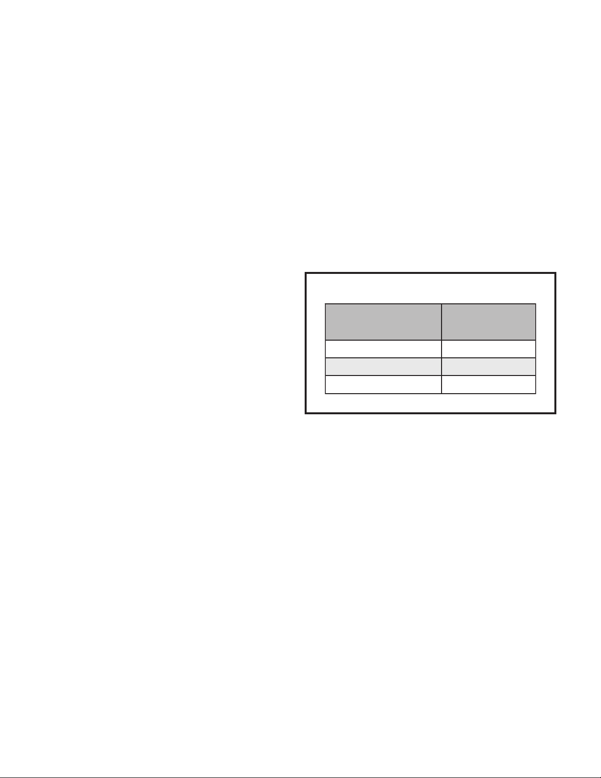
Torque Table
Table 1
renetsaF euqroT
spaCmetS.sbl.tf8
spaCtroPecivreS .sbl.tf8
swercSlateMteehS.sbl.ni61
swercSenihcaM8# .sbl.ni61
swercSenihcaM01#.sbl.ni82
stloBrosserpmoC .sbl.ni09
Figure 1
Installation Clearances
* A service clearance of 30" must be maintained on
one of the sides adjacent to the control box.
Clearance to one of the other three sides must be
36". Clearance to one of the remaining two sides
may be 12" and the final side may be 6".
A clearance of 24" must be maintained between units.
48" clearance required on top of unit. Maximum soffit
overhang is 36".
36 *"
36"
36"
36 *"

506253-01 Issue 0912Page 3
Electrical Wiring
All field wiring must be done in accordance with the
National Electrical Code (NEC) recommendations,
Canadian Electrical Code (CEC) and CSA Standards, or
local codes, where applicable.
Refer to the furnace or blower coil Installation Instructions
for additional wiring application diagrams and refer to unit
rating plate for minimum circuit ampacity and maximum
overcurrent protection size.
1. Install line voltage power supply to unit from a properly
sized disconnect switch. Any excess high voltage field
wiring should be trimmed or secured away from the
low voltage field wiring.
2. Ground unit at unit disconnect switch or to an earth
ground. To facilitate conduit, a hole is in the bottom of
the control box. Connect conduit to the control box
using a proper conduit fitting. Units are approved for
use only with copper conductors. 24V Class II circuit
connections are made to the low voltage pigtails. A
complete unit wiring diagram is located inside the unit
control box cover (see also page 22 of this instruction).
3. Install room thermostat on an inside wall that is not
subject to drafts, direct sunshine, or other heat sources.
4. Install low voltage wiring from outdoor to indoor unit and
from thermostat to indoor unit (see Figure 3).
Unit must be grounded in accordance with
national and local codes. Failure to ground unit
properly can result in personal injury or death.
WARNING
5. Do not bundle any excess 24V control wire inside control
box. Run control wire through installed wire tie and tighten
wire tie to provide low voltage strain relief and to maintain
separation of field-installed low and high voltage circuits.
Refrigerant Piping
Figure 2
Slab Mounting
Discharge Air
Mounting Slab
Ground Level
Building
Structure
Thermostat Designations
Figure 3
See unit wiring diagram for power supply connections.
If the indoor unit is not equipped with a blower relay,
one must be field supplied and installed.
Do not connect C (common) connection between
indoor unit and thermostat except when required by
the indoor thermostat. Refer to thermostat installation
instructions. C (common) connection between indoor
unit and outdoor unit required for proper operation.
Power
Indoor Unit
Thermostat
Outdoor Unit
Heat
Cooling
Indoor Blower
R
W1
Y
G
C
R
W
Y
G
C
Y2 Y2
R
W
Y
G
C
Y2
If the 4SCU16LT unit is being installed with a new indoor
coil and line set, the refrigerant connections should be
made as outlined in this section. If an existing line set and/
or indoor coil will be used to complete the system, refer to
this section as well as the section that follows entitled
Flushing Existing Line Set and Indoor Coil.
If this unit is being matched with an approved line set or
indoor coil which was previously charged with R22 refriger-
ant, the line set and coil must be flushed prior to installation.
If the unit is being used with an existing indoor coil which
was equipped with a liquid line which served as a metering
device (RFCI), the liquid line must be replaced prior to the
installation of the 4SCU16LT unit.
Field refrigerant piping consists of liquid and suction lines
from the outdoor unit (sweat connections) to the indoor
coil (flare or sweat connections).
Refrigerant can be harmful if inhaled. Refrigerant
must always be used and recovered responsibly.
Incorrect or irresponsible use of refrigerant can
result in personal injury or death.
WARNING

506253-01Page 4 Issue 0912
Selectlineset diametersfromTable2 toensurethatoilreturn
to the compressor. Size vertical suction riser to maintain
minimumvelocity atminimumcapacity. Recommended line
length is 50’ or less. If more than 50’ line set is required,
contact Technical Services.
Table 2showsthe diametersforline setsupto100’although
vertical lift applications and trapping requirements need to
be reviewed with Technical Services for line sets over 50’.
Installing Refrigerant Line
During the installation of an air conditioning system, it is
important to properly isolate the refrigerant line to prevent
unnecessary vibration. Line set contact with the structure
(wall,ceiling, orfloor) maycauseobjectionablemoisewhen
vibration is translated into sound. As a result, more energy
or vibration can be expected. Close attention to line set
isolation must be observed. If refrigeration lines are routed
through a wall, seal and isolate the opening so vibration is
not transmitted to the building.
Following are some points to consider when placing and
installing a high-efficiency outdoor unit:
Placement
Beawarethatsomelocalitiesareadoptingsoundordinances
based on how noisy the unit is at the neighbor’s home, not
at the original installation. Install the unit as far as possible
fromthe propertyline. When possible,do notinstallthe unit
directly outside a bedroom window. Glass has a very high
level of sound transmission. Figure 4 shows how to place
the outdoor unit and line set to reduce line set vibration.
Line Set Isolation
Illustrationson thefollowingpages demonstrateprocedures
which ensure proper refrigerant line set isolation. Figure 5
shows how to install line sets on horizontal runs. On page
6, Figure 6 shows how to make a transition from horizontal
to vertical and Figure 7 shows how to install line sets on
vertical runs.
Brazing Connection Procedure
1. Cut ends of refrigerant lines square (free from nicks or
dents). Debur the ends. The pipe must remain round; do
not pinch end of line.
2. Before making line set connections, use dry nitrogen to
purge the refrigerant piping. This will help to prevent
oxidation and the introduction of moisture into the system.
3. Use silver alloy brazing rods (5% or 6% silver alloy for
copper-to-copper brazing or 45% silver alloy for
Refrigerant Line Set Diameters (in.)
For installations exceeding 50’, contact
Technical Services.
Table 2
Suction Line
BTUH Line Set Length and Size
12 ft. 25 ft. 50 ft. 75 ft. 100 ft.
3/4 3/4
24,000 7/8
36,000
7/8
7/8
7/8
1-1/8
7/8
7/8
1-1/8
48,000
7/87/8
7/8
1-1/8
1-1/8
60,000 1-1/8
1-1/8
7/8
1-1/8 1-1/8
Liquid Line
BTUH Line Set Length and Size
12 ft. 25 ft. 50 ft. 75 ft. 10 0 ft.
3/8 3/8 3/8 3/8 3/8
24,000
3/8 3/8 3/8 3/8
3/8 3/8 3/8 1/2
36,000
3/8 3/8 3/8 1/2
48,000
60,000 1/2
1/2
1/2
Polyolester (POE) oils used with R-410A refrigerant
absorb moisture very quickly. It is very important that
the refrigerant system be kept closed as much as
possible. DONOTremovelinesetcapsorservice valve
stub caps until ready to make connections.
WARNING

506253-01 Issue 0912Page 5
Outside Unit Placement
and Installation
Figure 4
Install unit away
from windows
Two 90° elbows installed in lineset
will reduce lineset vibration
copper-to-brass or copper-to-steel brazing) which are
rated for use with R410A refrigerant.
4. Remove the Schrader core assemblies before brazing
to protect them from damage due to extreme heat.
Replace the cores when brazing is complete.
5. Remove light maroon washers from service valves and
shield light maroon stickers to protect them during
brazing. Wrap a wet cloth around the valve body and
copper tube stub to protect it from heat damage.
6. Braze the line set to the service valve. Quench the joints
with water or a wet cloth to prevent heat damage to the
valve core and opening port. The tube end must stay
bottomed in the fitting during final assembly to
ensure proper seating, sealing, and rigidity.
7. Install a thermal expansion valve (which is sold
separately and which is approved for use with R410A
refrigerant) in the liquid line at the indoor coil (see
Refrigerant Metering Device on page 8).
Figure 5
To hang line set from joist or rafter,
use either metal strapping material
or anchored heavy nylon wire ties.
Strapping Material
(around vapor line only)
8’
8’
Tape or Wire Tie
Strap the vapor line to the joist or rafter
at 8 intervals then strap the liquid line
to the vapor line.
’
Floor Joist or
Roof Rafter
Metal Sleeve
Floor Joist or Roof Rafter
Tape or Wire Tie
Wire Tie
(around vapor line only)
Refrigerant Line Sets: Installing Horizontal Runs

Page 6 Issue 0912506253-01
Figure 6
Refrigerant Line Sets: Transition from Vertical to Horizontal
Anchored
Heavy Nylon
Wire Tie
Wall
Stud
Metal Sleeve Vapor Line Wrapped
in Armaflex
–
Liquid Line
Wall
Stud
Automotive
Muffler-Type
Hanger
Strap Liquid
Line to Vapor
Line
Metal Sleeve Vapor Line Wrapped
in Armaflex
–
Liquid Line
Strap Liquid
Line to Vapor
Line
Figure 7
Refrigerant Line Sets: Installing Vertical Runs (new construction shown)
Outside Wall
Wood Block
Between Studs
IMPORTANT: Refrigerant
lines must not contact wall.
Vapor Line Liquid Line
Wire Tie
Inside Wall
Strap
Sleeve
Wire Tie
Wire Tie
Strap
Wood Block
Sleeve
Vapor Line Wrapped
with Armaflex
Liquid Line
Caulk
PVC Pipe Fiberglass
Insulation
Outside Wall
IMPORTANT:
Refrigerant
lines must not
contact structure.
NOTE: Similar installation practices
should be used if line set is to be
installed on exterior of outside wall.

506253-01 Issue 0912Page 7
Flushing Existing Line Set and Indoor Coil
This procedure should not be performed on systems
which contain contaminants, such as compressor
burn out.
Flushing Procedure
IMPORTANT: The line set and/or indoor coil must be
flushed with at least the same amount of refrigerant that
previously charged the system. Check the charge in the
flushing cylinder before flushing the unit.
1. Remove existing R22 refrigerant using the appropriate
procedure.
If the existing outdoor unit is not equipped with shutoff
valves, or if the unit is not operational AND the existing
R22 refrigerant will be used to flush the system:
Disconnect all power to the existing outdoor unit.
Connect the existing unit, a clean recovery cylinder, and
the recovery machine according to the instructions
provided with the recovery machine. Remove all R22
refrigerant from the existing system. Refer to the
gauges after shutdown to confirm that the entire system
is completely void of refrigerant. Disconnect the liquid
and suction lines from the existing outdoor unit.
If the existing outdoor unit is equipped with manual
shutoff valves AND new R22 refrigerant will be used
to flush the system:
Start the existing R22 refrigerant system in cooling mode
and close the liquid line valve. Pump all the existing R22
refrigerant back into the outdoor unit.
Required Equipment
The following equipment is needed to flush the existing
line set and indoor coil (see Figure 8): Two clean R22
recovery bottles, an oil-less recovery machine with a
“pump down” feature, and two sets of gauges (one for use
with R22 and one for use with R410A).
Figure 8
Flushing Connections
Note: The inverted R22 cylinder must contain
at least the same amount of refrigerant
as was recovered from the existing
system.
When flushing existing line set and/or indoor
coil, be sure to empty all existing traps. Residual
mineral oil can act as an insulator, preventing
proper heat transfer. It can also clog the thermal
expansion valve, reducing system performance
and capacity. Failure to properly flush system as
explained in these instructions will void warranty.
CAUTION
Page 8 Issue 0912506253-01
(It may be necessary to bypass the low pressure
switches to ensure complete refrigerant evacuation.)
When the low side system pressures reach 0 psig, close
the suction line valve. Disconnect all power to the
existing outdoor unit. Refer to the gauges after shutdown
to confirm that the valves are not allowing refrigerant to
flow back into the low side of the system. Disconnect the
liquid and suction lines from the existing outdoor unit.
2. Remove the existing outdoor unit. Set the new R410A
unit and follow the brazing connection procedure
outlined previously on this page to make line set
connections. Do not install the R410A thermal
expansion valve at this time.
3. Make low voltage and line voltage connections to the
new outdoor unit. Do not turn on power to the unit or
open the outdoor unit service valves at this time.
4. Remove the existing R-22 refrigerant flow control
orifice or thermal expansion valve before continuing
with flushing procedures. R-22 flow control devices
are not approved for use with R410A refrigerant and
may prevent proper flushing. Use a field-provided
fitting to reconnect the lines.
5. Remove the pressure tap valve cores from the
4SCU16LT unit’s service valves. Connect an R-22
cylinder with clean refrigerant to the suction service
valve. Connect the R-22 gauge set to the liquid line
valve and connect a recovery machine with an empty
recovery tank to the gauge set.
6. Set the recovery machine for liquid recovery and start
the recovery machine. Open the gauge set valves to
allow the recovery machine to pull a vacuum on the
existing system line set and indoor coil.
7. Invert the cylinder of clean R-22 and open its valve to
allow liquid refrigerant to flow into the system through
the suction line valve. Allow the refrigerant to pass
from the cylinder and through the line set and the
indoor coil before it enters the recovery machine.
8. After all of the liquid refrigerant has been recovered,
switch the recovery machine to vapor recovery so that
all of the R-22 vapor is recovered. Allow the recovery
machine to pull a vacuum on the system.
NOTE: A single system flush should remove all of the
mineral oil from the existing refrigerant lines and indoor
coil. A second flushing may be done (using clean
refrigerant) if insufficient amounts of mineral oil were
removed during the first flush. After each system
flush, allow the recovery machine to pull a vacuum
on the system at the end of the procedure.
9. Close the valve on the inverted R22 cylinder and the
gauge set valves. Pump the remaining refrigerant out
of the recovery machine and turn the machine off.
10. Use nitrogen to break the vacuum on the refrigerant lines
and indoor coil before removing the recovery machine,
gauges, and R22 refrigerant drum. Re-install pressure tap
valve cores into the 4SCU16LT unit’s service valves.
11. Install a thermal expansion valve approved for use with
R410A refrigerant in the liquid line at the indoor coil.
Refrigerant Metering Device
4SCU16LT units are designed for use with TXV systems only.
Expansion valves equipped with Chatleff-type fittings are
available from the manufacturer. See Table 3 for proper
TXV for each unit.
To install an expansion valve (see Figure 9):
1. Separate the distributor assembly and remove the
piston orifice and used teflon seal. Insert nozzle end of
the expansion valve along with a new teflon seal into the
distributor and tighten to 20 – 30 ft. lbs. Use backup
wrench on all wrench flats. Overtightening will crush
the teflon seal and may cause a leak.
2. Attach liquid line portion of distributor assembly along
with new teflon seal to the inlet of the expansion
valve. Tighten to 20 – 30 ft. lbs. Use backup wrench
on all wrench flats. Overtightening will crush the
teflon seal and may cause a leak.
3. Connect the external equalizer line to the equalizer
port on the suction line and tighten to 8 ft. lbs.
4. Strap the superheat sensing bulb to the suction header.
If installing an expansion valve on an indoor coil that
previously used a fixed orifice, be sure to remove the
existing fixed orifice. Failure to remove a fixed orifice
when installing an expansion valve to the indoor coil will
result in improper operation and damage to the system.
Table 3
TXV Data
ledoM rebmuNtraP
63-,42-TL61UCS410VXT4A
TL61UCS484- 20VXT4A
TL61UCS406-30VXT4H

506253-01 Issue 0912Page 9
To Close Liquid or Suction Line Service Valve:
1. Remove the stem cap with an adjustable wrench.
2. Use a service wrench with a hex-head extension to turn
the stem clockwise to seat the valve. Tighten firmly.
3. Replace the stem cap. Tighten finger tight, then
tighten an additional 1/6 turn.
Suction Line (Ball Type) Service Valve
Suction line (ball type) service valves function the same
way as the other valves; the difference is in the construc-
tion (see Figure 11 on page 10).
The ball valve is equipped with a service port with a
factory-installed Schrader valve. A service port cap
protects the Schrader valve from contamination and
serves as the primary seal.
Manifold Gauge Set
Manifold gauge sets used with systems charged with
R410A refrigerant must be capable of handling the higher
system operating pressures. The gauges should be rated
for use with pressures 0 – 800 on the high side and a low
side of 30" vacuum to 250 psi with dampened speed to
500 psi. Gauge hoses must be rated for use at up to 800
psi of pressure with a 4000 psi burst rating.
Liquid and Suction Line Service Valves
The liquid line and suction line service valves and service
ports are used for leak testing, evacuating, charging, and
checking charge.
Each valve is equipped with a service port which has a
factory-installed Schrader valve (see Figure 10). A service
port cap protects the Schrader valve from contamination
and serves as the primary leak seal.
To Access the Schrader Port:
1. Remove the service port cap with an adjustable wrench.
2. Connect gauge to the service port.
3. When testing is completed, replace service port cap.
Tighten finger tight, then an additional 1/6 turn.
To Open Liquid or Suction Line Service Valve:
1. Remove stem cap with an adjustable wrench.
2. Use a service wrench with a hex-head extension to
back the stem out counterclockwise as far as it will
go. Use a 3/16" hex head extension for liquid line
service valves and a 5/16" extension for suction line
service valves.
3. Replace the stem cap. Tighten finger tight, then
tighten an additional 1/6 turn.
Metering Device Installation
Figure 9
Figure 10
Service Valve
Valve Closed
Valve Open

Page 10 Issue 0912506253-01
Leak Testing
After the line set has been connected to the indoor and
outdoor units, the line set connections and indoor unit
must be checked for leaks.
Figure 11
2. With both manifold valves closed, connect the cylin-
der of R410A refrigerant. Open the valve on the
R410A cylinder (vapor only).
3. Open the high pressure side of the manifold to allow
R410A into the line set and indoor unit. Weigh in a
trace amount of R410A. (A trace amount is a maxi-
mum of 2 oz. of refrigerant or 3 lbs. pressure.) Close
the valve on the R410A cylinder and the valve on the
high pressure side of the manifold gauge set. Discon-
nect the R410A cylinder.
4. Connect a cylinder of nitrogen with a pressure regulat-
ing valve to the center port of the manifold gauge set.
When using high pressure gas such as nitrogen
for this purpose, be sure to use a regulator that
can control the pressure down to 1 or 2 psig.
5. Adjust nitrogen pressure to 150 psig. Open the valve
on the high side of the manifold gauge set to pressur-
ize the line set and the indoor coil.
6. After a short period of time, open a refrigerant port to
make sure that an adequate amount of refrigerant has
been added for detection (refrigerant requirements will
vary with lengths). Check all joints for leaks. Purge
nitrogen and R410A mixture. Correct any leaks and
recheck.
Evacuation
Evacuating the system of noncondensables is critical for
proper operation of the unit. Noncondensables are defined
as any gas that will not condense under temperatures and
pressures present during operation of an air conditioning
system. Noncondensables and water vapor combine with
refrigerant to produce substances that corrode copper
piping and compressor parts.
Using an Electronic Leak Detector
1. Connect the high pressure hose of the manifold
gauge set to the suction valve service port. (Normally
the high pressure hose is connected to the liquid line
port; however, connecting it to the suction ports helps
to protect the manifold gauge set from damage
caused by high pressure.)
Use a thermocouple or thermistor electronic vacuum
gauge that is calibrated in microns. Use an instrument that
reads down to 50 microns.
1. Connect the manifold gauge set to the service valve
ports as follows:
• Low pressure gauge to suction line service valve
• High pressure gauge to liquid line service valve
Do not use a compressor to evacuate a sys-
tem. Avoid deep vacuum operation. Extremely
low vacuums can cause internal arcing and
compressor failure. Danger of equipment
damage. Damage caused by deep vacuum
operation will void warranty.
WARNING
Ball Type Service Valve
(Valve Open)
Use adjustable wrench. To open, rotate stem
counterclockwise 1/4 turn (90°). To close, rotate
stem clockwise 1/4 turn (90°).
Fire, Explosion, and Personal Safety Hazard.
Failure to follow this warning could result in
damage, personal injury, or death.
Never use oxygen to pressurize or purge
refrigeration lines. Oxygen, when exposed to
a spark or open flame, can cause damage by
fire and/or an explosion, that could result in
personal injury or death.
WARNING

506253-01 Issue 0912Page 11
2. Connect micron gauge.
3. Connect the vacuum pump (with vacuum gauge) to
the center port of the manifold gauge set.
4. Open both manifold valves and start vacuum pump.
5. Evacuate the line set and indoor unit to a minimum of 500
microns or lower. During the early stages of evacuation, it
is desirable to close the manifold gauge valve at least
once to determine if there is a rapid rise in pressure. A
rapid rise in pressure indicates a relatively large leak. If
this occurs, the leak testing procedure must be repeated.
6. When 500 microns or lower is maintained, close the
manifold gauge valves, turn off the vacuum pump, and
disconnect the manifold gauge center port hose from
the vacuum pump. Attach the manifold gauge center
port hose to a nitrogen cylinder with pressure regulator
set to 150 psig and purge the hose. Open the manifold
gauge valves to break the vacuum in the line set and
indoor unit. Close the manifold gauge valves.
7. Shut off the nitrogen cylinder and remove the manifold
gauge hose from the cylinder. Open the manifold
gauge valves to release the nitrogen from the line set
and indoor unit.
8. Reconnect the manifold gauge to the vacuum pump,
turn the pump on, and continue to evacuate the line
set and indoor unit until 500 microns is maintained
within a 20-minute period after shutting off the
vacuum pump and closing the manifold gauge valves.
9. When the requirements above have been met,
disconnect the manifold hose from the vacuum pump.
Open the service valves to break the vacuum in the
line set and indoor unit.
Page 12 Issue 0912506253-01
If the system is void of refrigerant, clean the system using
the procedure described below.
1. Use dry nitrogen to pressurize the system and check
for leaks. Repair leaks, if possible.
2. Evacuate the system to remove as much of the
moisture as possible.
3. Use dry nitrogen to break the vacuum.
4. Evacuate the system again.
5. Weigh the appropriate amount of R410A refrigerant
(listed on unit nameplate) into the system.
6. Monitor the system to determine the amount of
moisture remaining in the oil. Use a test kit to verify
that the moisture content is within the kit’s dry color
range. It may be necessary to replace the filter drier
several times to achieve the required dryness level. If
system dryness is not verified, the compressor
will fail in the future.
The outdoor unit should be charged during warm weather.
However, applications arise in which charging must occur
in the colder months. The method of charging is deter-
mined by the outdoor ambient temperature.
Measure the liquid line temperature and the outdoor
ambient temperature as outlined below:
1. Connect the manifold gauge set to the service valve
ports as follows:
• Low pressure gauge to suction line service valve
• High pressure gauge to liquid line service valve
START-UP
1. Rotate fan to check for frozen bearings or binding.
2. Inspect all factory and field-installed wiring for loose
connections.
3. After evacuation is complete, open liquid line and
suction line service valves to release refrigerant
charge (contained in outdoor unit) into system.
4. Replace the stem caps and secure finger tight, then
tighten an additional 1/6 of a turn.
5. Check voltage supply at the disconnect switch. The
voltage must be within the range listed on the unit
nameplate. If not, do not start equipment until the
power company has been consulted and the voltage
condition corrected.
6. Set thermostat for cooling demand, turn on power to
indoor blower and close the outdoor unit disconnect
switch to start the unit.
7. Recheck unit voltage with unit running. Power must be
within range shown on unit nameplate.
Refrigerant Charging
This system is charged with R410A refrigerant which
operates at much higher pressures than R22. The liquid line
drier provided with the unit is approved for use with R410A.
Do not replace it with one designed for use with R22. This
unit is NOT approved for use with coils which use
capillary tubes as a refrigerant metering device.
R410A refrigerant cylinders are rose colored. Refriger-
ant should be added through the vapor valve in the
liquid state.
Certain R410A cylinders are identified as being
equipped with a dip tube. These allow liquid refriger-
ant to be drawn from the bottom of the cylinder
without inverting the cylinder. Do not turn this type of
cylinder upside down to draw refrigerant.
Units are factory charged with the amount of R410A
refrigerant indicated on the unit rating plate. This charge is
based on a matching indoor coil and outdoor coil with 15'
line set. For varying lengths of line set, refer to Table 4 for
refrigerant charge adjustment.
If unit is equipped with a crankcase heater, it
should be energized 24 hours before unit
start-up to prevent compressor damage as a
result of slugging.
CAUTION
Mineral oils are not compatible with R410A. If
oil must be added, it must be a polyol ester oil.
IMPORTANT
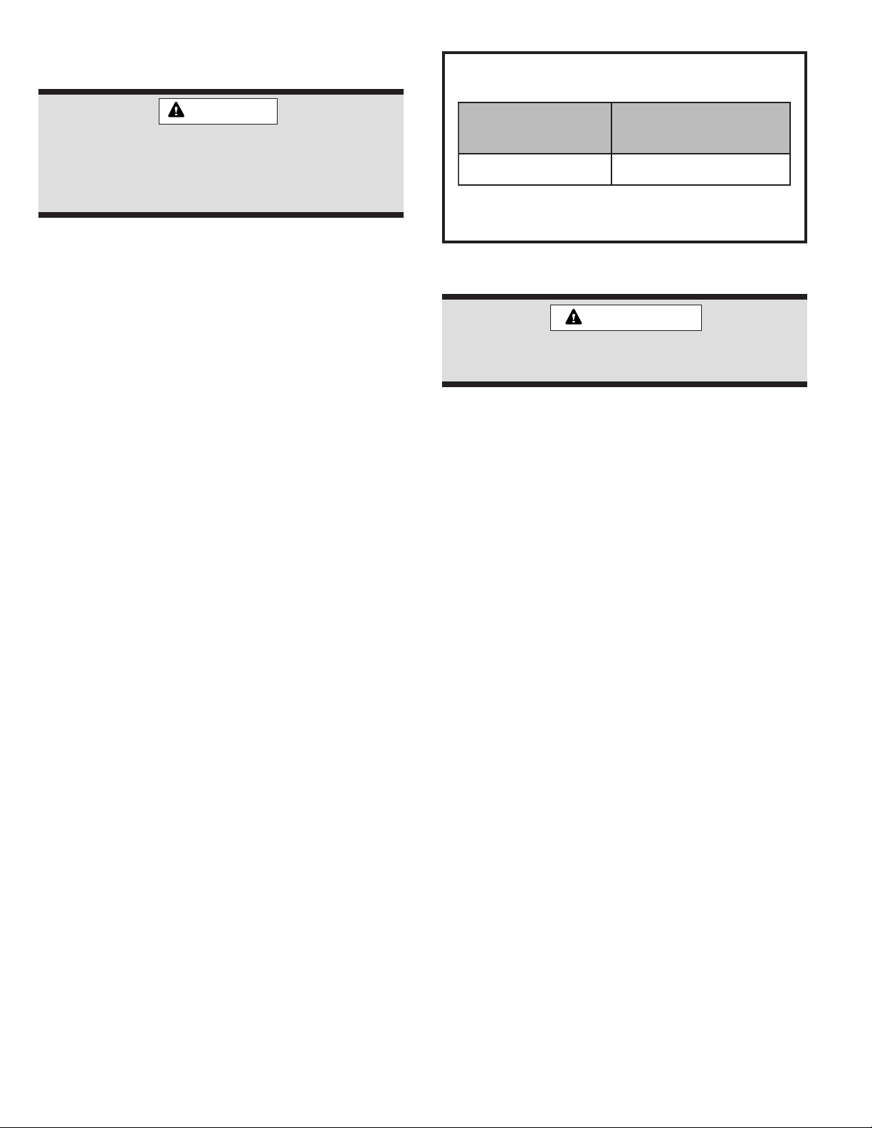
Refrigerant Charge Adjustment
* If line length is greater than 15 ft., add this amount.
If line length is less than 15 ft., remove this amount.
Table 4
teSeniLdiuqiL
retemaiD
tsujda.tf5rep.zO
*tesenil.tf51morf
.ni8/3.tf5rep.zo3
506253-01 Issue 0912Page 13
2. Close manifold gauge set valves. Connect the center
manifold hose to an upright cylinder of R410A.
3. If room temperature is below 70°F, set the room thermo-
stat to call for heat. This will create the necessary load
for properly charging the system in the cooling cycle.
4. Use a digital thermometer to record the outdoor
ambient temperature.
5. When the heating demand has been satisfied, switch
the thermostat to cooling mode with a set point of
68°F. When pressures have stabilized, use a digital
thermometer to record the liquid and suction line
temperatures.
6. The outdoor temperature will determine which charg-
ing method to use. Proceed with the appropriate
charging method.
Charge Using Weigh-In Method
If the system is void of refrigerant, or if the outdoor ambient
temperature is cool, first locate and repair any leaks then
use the weigh-in method to charge the unit.
1. Recover the refrigerant from the unit.
2. Conduct a leak check, then evacuate as previously
outlined.
3. Weigh in the charge according to the total amount
shown on the unit nameplate.
If weighing facilities are not available, use one of the
following procedures to charge the unit.
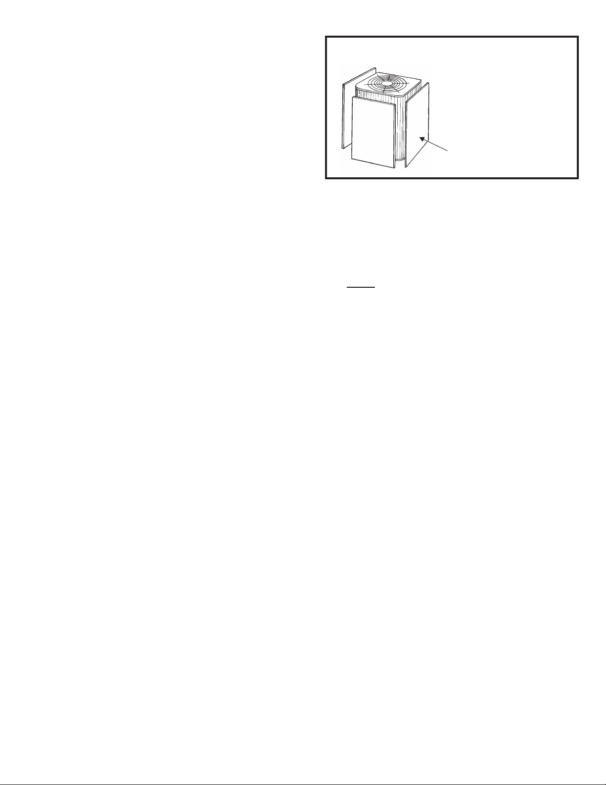
Charge Using Subcooling Method –
Outdoor Temperatures Below 65°F
When the outdoor ambient temperature is below 65°F, the
subcooling method can be used to charge the unit. It may
be necessary to restrict the air flow through the outdoor
coil to achieve pressures in the 200-250 psig range.
These higher pressures are necessary for checking the
charge. Block equal sections of air intake panels and
move obstructions sideways until the liquid pressure is in
the 200-250 psig range (see Figure 12).
1. With the manifold gauge hose on the liquid service
port and the unit operating stably, use a digital ther-
mometer to record the liquid line temperature.
2. At the same time, record the liquid line pressure reading.
3. Use the temperature/pressure chart (Table 5 on page 14)
to determine the saturation temperature for the liquid line
pressure reading.
4. Subtract the liquid line temperature from the satura-
tion temperature (according to the chart) to determine
subcooling.
_____ ° Saturation Temperature °F
_____ ° Liquid Line Temperature °F
_____ ° Subcooling Value °F
–
=
5. Compare the subcooling value with those shown in
Table 6 on page 14. If subcooling is greater than
shown, recover some refrigerant. If subcooling is less
than shown, add some refrigerant.
Charge Using Approach Method –
Outdoor Temperatures 65°F or Above
The following procedure is intended as a general guide
and is for use on expansion valve systems only. For best
results, indoor temperature should 70°F to 80°F. Monitor
system pressures while charging.
1. Record outdoor ambient temperature using a digital
thermometer.
2. Attach high pressure gauge set and operate unit for
several minutes to allow system pressures to stabilize.
3. Compare stabilized pressures with those provided in
Table 8 on page 15. Minor variations in these pres-
sures may be expected due to differences in installa-
tions. Significant differences could mean that the
system is not properly charged or that a problem
exists with some component in the system.
Pressures higher than those listed indicate that the
system is overcharged. Pressures lower than those
listed indicate that the system is undercharged. Verify
adjusted charge using the approach method.
4. Use the same digital thermometer to check liquid line
temperature.
5. Subtract the outdoor ambient temperature from the
liquid line temperature to determine the approach
temperature.
Figure 12
Outdoor coil should be
blocked one side at a time
with cardboard or plastic
sheet until proper testing
pressures are reached.
Blocking Outdoor Coil
Cardboard or Plastic Sheet

Page 14 Issue 0912506253-01
_____ ° Liquid Line Temperature °F
_____ ° Outdoor Ambient Temperature °F
_____ ° Approach Temperature °F
–
=
6. Compare the approach value with those shown in
Table 7. If the values to do not agree with those
provided in Table 7, add refrigerant to lower the
approach temperature or recover refrigerant from the
system to increase the approach temperature.
Check Charge Using Normal Operating Pressures
Use Table 8 to perform maintenance checks. Table 8 is
not a procedure for charging the system. Minor variations
in these pressures may be due to differences in installa-
tions. Significant deviations could mean that the system is
not properly charged or that a problem exists with some
component in the system.
R410A Temperature/Pressure Chart
Table 5
.pmeT
F°
erusserP
gisP
238.001
339.201
430.501
531.701
632.901
734.111
836.311
938.511
040.811
143.021
246.221
340.521
443.721
547.921
642.231
746.431
841.731
946.931
052.241
158.441
254.741
351.051
458.251
555.551
652.851
750.161
859.361
957.661
066.961
166.271
265.571
365.871
466.181
563.481
667.781
769.091
861.491
963.791
076.002
179.302
272.702
376.012
.pmeT
F°
erusserP
gisP
470.412
574.712
679.022
774.422
870.822
976.132
083.532
180.932
287.242
385.642
483.052
581.452
680.852
780.262
880.662
980.072
091.472
192.872
293.282
395.682
498.092
591.592
694.992
798.303
892.803
997.213
0012.713
1018.123
2014.623
3010.133
4017.533
5015.043
6013.543
7011.053
8010.553
9010.063
0110.563
1110.073
2111.573
3112.083
4114.583
5117.093
.pmeT
F°
erusserP
gisP
6110.693
7113.104
8117.604
9112.214
0217.714
1212.324
2218.824
3215.434
4212.044
5219.544
6218.154
7216.754
8215.364
9215.964
0316.574
1316.184
2318.784
3310.494
4312.005
5315.605
6319.215
7313.915
8318.525
9314.235
0410.935
1416.545
2413.255
3411.955
4419.565
5418.275
6418.975
7418.685
8418.395
9410.106
0511.806
1514.516
2517.226
3511.036
4515.736
5510.546
Subcooling Values
Table 6
ledoM 42- 63- 84- 06-
F°.pmeT5669
Approach Values for TXV Systems
Approach value is the liquid line temperature
minus the outdoor ambient temperature (±1°F).
NOTE: For best results, use the same digital
thermometer to check both outdoor ambient and
liquid temperatures.
Table 7
ledoM 42- 63- 84- 06-
F°.pmeT80184

506253-01 Issue 0912Page 15
Normal Operating Pressures
L = Liquid S = Suction
Table 8
Values provided above are typical pressures. Indoor unit matchup, indoor air quality, and indoor load will cause
pressures to vary.
foerutarepmeT
gniretnEriAeht
lioCroodtuOeht
ledoM
42- 63- 84- 06-
L S L S L S L S
1
ts
)yticapaCwoL(egatS
F°56442631832331742031052521
F°57382831872531182431192721
F°58623141423731523731433031
F°59673241473931683931383331
F°5
01824441924241824141434631
F°511684641005441584441984931
2
dn
)yticapaChgiH(egatS
F°56 942 621 152 921 942 321 342 711
F°57 882 331 192 531 682 921 582 321
F°58 133 831 433 931 823 331 923 921
F°59 973 341 383 341 273 731 673 431
F°501 524 741 534 741 914 141 724 731
F°511 184 051 094 051 574 541 584 141

Page 16 Issue 0912506253-01
OPERATION
Outdoor unit and indoor blower cycle on demand from the
room thermostat. When the thermostat blower switch is
moved to the ON position, the indoor blower operates
continuously.
System Diagnostic Module
4SCU16LT units contain a diagnostic module for trouble-
shooting air conditioning system failures. By monitoring
and analyzing data from the compressor and thermostat
demand, the module can accurately detect the cause of
electrical and system related failure without any sensors.
If a system problem occurs, a flashing LED indicator
communicates the failure code.
LED Description
POWER LED (Green) indicates voltage is present at the
power connection of the module.
ALERT LED (Yellow) communicates an abnormal system
condition through a unique flash code. The ALERT LED
will flash a number of times consecutively, pause, and
then repeat the process. The number of consecutive
flashes correlates to a particular abnormal condition.
TRIP LED (Red) indicates there is a demand signal from
the thermostat but no current to the compressor is de-
tected by the module. The TRIP LED typically indicates
the compressor protector is open or may indicate missing
supply power to the compressor.
Interpreting the Diagnostic LEDs
When an abnormal system condition occurs, the diagnostic
module displays the appropriate ALERT and/or TRIP LED.
The yellow ALERT LED will flash a number of times
consecutively, pause, and then repeat the process. To
identify a flash code number, count the number of consecu-
tive flashes. Refer to Table 9 on page 17 and Table 10 on
page 18 for information on the flash codes.
Every time the module powers up, the last ALERT LED
flash code that occurred prior to shutdown is displayed for
60 seconds. The module will continue to display the
previous flash code until the condition returns to normal or
24VAC is removed from the module. TRIP and ALERT
LEDs flashing at the same time means control circuit
voltage is too low for operation.
24VAC Power Wiring
The diagnostic module requires a constant nominal 24VAC
power supply. The wiring to the module’s R and C terminals
must be directly from the indoor unit or thermostat.
Thermostat Demand Wiring
The diagnostic module requires a thermostat demand
signal to operate properly. The thermostat demand signal
input, labeled Y on the module, should always be con-
nected to the compressor contactor coil so that when the
coil is energized, the demand signal input is 24VAC. When
the coil is not energized, the demand signal input should be
less than 0.5VAC.
Miswired Module Codes
Depending on the system configuration, some ALERT
flash codes may not be active. The presence of safety
switches affects how the system alerts are displayed by
the module.
Miswiring the diagnostic module will cause false LED
codes. Table 11 on page 19 describes LED operation
when the module is miswired and what troubleshooting
action is required to correct the problem.

506253-01 Issue 0912Page 17
Flash Codes
Table 9
DEL
sutatS noitpircseDtluaF noitamrofnIgnitoohselbuorT
REWOP
)neerG(
rewopsaheludoMslanimreteludomtatneserpsiegatlovylppuS
PIRT
)deR(
dnamedtatsomrehT
,tneserpsi1Ylangis
rosserpmocehttub
gninnurtonsi
neposirotcetorprosserpmoC.1
erusserpdaehhgihrofkcehC*
egatlovylppusrosserpmockcehC*
nepositcennocsidrewoptinuroodtuO.2
neposi)s(esufrorekaerbtiucricrosserpmoC.3
tcatnocgnikamtonsirotcennocroeriwnekorB.4
metsysnitneserpfinepohctiwserusserpwoL.5
nepodeliafsahrotcatnocrosserpmoC.6
TRELA
)wolleY(
hsalF
1edoC
miTnuRgnoLee
e
ee
sirosserpmoC
gninnur
nurgnolylemertxe
selcyc
egrahctnaregirferwoL.1
gninnurtonsirewolbrotaropavE.2
stcatnocdnaliocyalerrewolbkcehC*
roticapacrotomrewolbkcehC*
egakcolbroeruliafrofrotomrewolbkcehC*
rotcennocdnagniriwrewolbrotaropavekcehC*
draoblortnocrewolbroodnikcehC*
tiucricneporofgniriwtatsomrehtkcehC*
nezorfsiliocrotaropavE.3
erusserpnoitcuswolrofkcehC*
gnittestatsomrehtwolylevissecxerofkcehC*
)retlifrianruterrosegakcolblioc(wolfriarotaropavekcehC*
egakcolbrofsretsigerrokrowtcudkcehC*
ecivedgniretemytluaF.4
)tcatnocdna,noitacol,ezis(noitallatsniblubVXTkcehC*
evitcefedrodesolckcutssiecifirodexif/VXTfikcehC*
ytridsiliocresnednoC.5
)metsysnitneserpfidekcolbreirdretlif(noitcirtserenildiuqiL.6
gninoitcnuflamsitatsomrehT.7
tiucrictrohsrofgniriwroesab-bustatsomrehtkcehC*
)level,noitacol(noitallatsnitatsomrehtkcehC*
TRELA
)wolleY(
hsalF
2edoC
metsyS
pirTerusserP
noitcusroegrahcsiD
erusserp
rostimilfotuo
rosserpmoc
dedaolrevo
erusserpdaehhgiH.1
metsysnitneserpfihctiwserusserphgihkcehC*
tnaregirferhtiwdegrahcrevosimetsysfikcehC*
metsysnielbasnednoc-nonrofkcehC*
)degamad,dekcolb,ytrid(noitalucricriaroopliocresnednoC.2
gninnurtonsinafresnednoC.3
roticapacnafkcehC*
srotcennocdnagniriwnafkcehC*
egakcolbroeruliafrofrotomnafkcehC*
egakaellaitnatsbussahtcudrianruteR.4
ofni1edoChsalFkcehc,metsysnitneserphctiwserusserpwolfI.5

Page 18 Issue 0912506253-01
Flash Codes (cont.)
Table 10
DEL
sutatS noitpircseDtluaF noitamrofnIgnitoohselbuorT
TRELA
)wolleY(
hsalF
3edoC
gnilcyCtrohS
sirosserpmoC
gninnur
ylfeirbylno
tnettimret
nisilangisdnamedtatsomrehT.1
evitcefeddraoblortnocroyaleryaledemiT.2
ofni2edoChsalFotog,tneserphctiwserusserphgihfI.3
ofni1edoChsalFotog,tneserphctiwserusserpwolfI.4
TRELA
)wolleY(
hsalF
4edoC
rotoRdekcoL
deliafsahroticapacnuR.1
)wolsitcennocsidtaegatlovfiytilitutcatnoc(egatlovenilwoL.2
snoitcennocgniriwkcehC*
rosserpmocnitnaregirferdiuqilevissecxE.3
dezieserasgniraebrosserpmoC.4
levelliorosserpmocerusaeM*
TRELA
)wolleY(
hsalF
5edoC
tiucriCnepO
nepositcennocsidrewoptinuroodtuO.1
neposi)s(esufrorekaerbtiucricrosserpmoC.2
nepodeliafsahrotcatnocrosserpmoC.3
srotcennocdnagniriwrotcatnocrosserpmockcehC*
)neporo,dettip,denrub(eruliafrotcatnocrosserpmocrofkcehC*
rosserpmocdnaylppusneewtebsrotcennocdnagniriwkcehC*
liocrotcatnocrosserpmoctaegatlovtolipwolrofkcehC*
teserlaunamseriuqerdnaneposihctiwserusserphgiH.4
snoitcennocrogniriwylppusrosserpmocnitiucricnepO.5
erutarepmettneibmaemertxeoteudemitteserrotcetorprosserpmocgnolyllausunU.6
degamaderasgnidniwrosserpmoC.7
ecnatsisergnidniwrotomrosserpmockcehC*
TRELA
)wolleY(
hsalF
6edoC
tiucriCtratSnepO
nurniylnotnerruC
tiucric
deliafsahroticapacnuR.1
snoitcennocrogniriwtratsrosserpmocnitiucricnepO.2
lanimretSrosserpmocehtdnaylppusneewtebsrotcennocdnagniriwkcehC*
degamadsignidniwtratsrosserpmoC.3
ecnatsisergnidniwrotomrosserpmockcehC*
TRELA
)wolleY(
hsalF
7edoC
tiucriCnuRnepO
tratsniylnotnerruC
tiucric
snoitcennocrogniriwnurrosserpmocnitiucricnepO.1
lanimretRrosserpmocehtdnaylppusneewtebsrotcennocdnagniriwkcehC*
degamadsignidniwnurrosserpmoC.2
ecnatsisergnidniwrotomrosserpmockcehC*
TRELA
)wolleY(
hsalF
8edoC
rotcatnoCdedleW
syawlarosserpmoC
snur
desolcdeliafsahrotcatnocrosserpmoC.1
eludomotdetcennoctonlangisdnamedtatsomrehT.2
TRELA
)wolleY(
hsalF
9edoC
egatloVwoL
sseltiucriclortnoC
CAV71naht
dedaolrevosiremrofsnarttiucriclortnoC.1
)wolsitcennocsidtaegatlovfiytilitutcatnoc(egatlovenilwoL.2
snoitidnocgniriwkcehC*

506253-01 Issue 0912Page 19
Table 11
Miswired Module Troubleshooting
noitacidnIeludoMderiwsiM noitcAgnitoohselbuorTdednemmoceR
,notonsiDELneerG
.purewoptonseodeludom
tneserpsiegatlovyfireV.detcennoc
eraslanimreteludomCdnaRhtobfienimreteD
rof61egapnonoitcesgniriWrewoPCAV42weiveR.slanimretCdnaRs'eludomta
.gniriwCdnaR
,tnettimretniDELneerG
ylnopusrewopeludom
.snurrosserpmocnehw
CdnaRs'eludomyfireV.esrevernideriweraslanimretYdnaRfienimreteD
61egapnonoitcesgniriWrewoPCAV42weiveR.ecruostnatsnocaevahslanimret
.gniriwCdnaRrof
metsystubnosiDELPIRT
.KOkcehcrosserpmocdna
rotcatnoctaegatlovyfireV.liocrotcatnoctaCAV42otdetcennocsilanimretYyfireV
.ffonehwCAV5.0wolebsllafslioc
DELTRELAdnaDELPIRT
.rehtegotgnihsalf .CAV82-91htiwdeilppuseraslanimretCdnaRyfireV
3edoChsalFTRELA
)gnilcyCtrohSrosserpmoC(
.yltcerrocnideyalpsid
rotcatnoctaegatlovyfireV.liocrotcatnoctaCAV42otdetcennocsilanimretYyfireV
.ffonehwCAV5.0wolebsllaflioc
7ro,6,5edoChsalFTRELA
tratSnepO,tiucriCnepO(
)tiucriCnuRnepOro,tiucriC
.yltcerrocnideyalpsid
gnisnestnerrucs'eludomhguorhteraseriwtratsdnanurrosserpmoctahtkcehC
taegatlovyfireV.liocrotcatnoctaCAV42otdetcennocsilanimretYyfireV.seloh
.ffonehwCAV5.0wolebsllafliocrotcatnoc
6edoChsalFTRELA
)tiucriCtratSnepO(
7edoCrofdeyalpsid
tiucriCnuRnepO(
.asrevecivro
eludomtcerrochguorhtdetuoreraseriwtratsdnanurrosserpmoctahtkcehC
.selohgnisnes
8edoChsalFTRELA
)rotcatnoCdedleW(
.yltcerrocnideyalpsid
taCAV42otdetcennocsilanimretYyfireV.detcennocsilanimretYs'eludomfienimreteD
silangisdnamedtatsomrehtnehwCdnaYssorcatneserpsiCAV42yfireV.liocrotcatnoc
wolebsllafliocrotcatnoctaegatlovyfireV.deriwesrevereraCdnaR,tonfI.tneserp
.gniriwCdnaYrof61egapnogniriWdnameDtatsomrehTweiveR.ffonehwCAV5.0

Page 20 Issue 0912506253-01
4. Check all wiring for loose connections.
5. Check for correct voltage at unit (with unit operating).
6. Check amp-draw on blower motor.
Unit nameplate _________ Actual _________
Maintenance and service must be performed by a quali-
fied installer or service agency.
At the beginning of each cooling season, the system
should be checked as follows:
1. Clean and inspect condenser coil. Coil may be
flushed with a water hose. Be sure the power is off
before using water to clean the coil.
2. Outdoor fan motor is pre-lubricated and sealed. No
further lubrication is needed.
3. Visually inspect connecting lines and coils for evi-
dence of oil leaks.
4. Check wiring for loose connections.
5. Check for correct voltage at unit (with unit operating).
6. Check amp-draw outdoor fan motor.
Unit nameplate _________ Actual _________
NOTE – If owner complains of insufficient cooling, the
unit should be gauged and refrigerant charge checked.
Refer to the Refrigerant Charging section on page 12.
Indoor Coil
1. Clean coil, if necessary.
2. Check connecting lines and coils for evidence of oil
leaks.
3. Check condensate pan line and clean, if necessary.
Indoor Unit
1. Clean or change filters.
2. Adjust blower speed for cooling. Measure the pressure
drop over the coil to determine the correct blower CFM.
3. Belt drive blowers: Check belt for wear and proper
tension.
MAINTENANCE
Before performing maintenance operations on
system, turn the electric power to unit OFF at
disconnect switch(es). Unit may have multiple
power supplies. Electrical shock could cause
personal injury or death.
WARNING
Table of contents
Other Allied Air Air Conditioner manuals


Popular Air Conditioner manuals by other brands


Lennox
Lennox LIFHC012021T431E-1 owner's manual

Haier
Haier HBU-18CA03T3 Operation & installation manual

Daikin
Daikin FXFQ07TVJU Operation manual

Samsung
Samsung AR Series user manual

Mitsubishi Electric
Mitsubishi Electric City Multi PLFY-WL-VEM-E Series installation manual

Panasonic
Panasonic CS-C12MKF-2 operating instructions