Allied Air 4SCU14LE SERIES User manual

506251-01 Page 1 of 20Issue 1015
TABLE OF CONTENTS
INSTALLATION ...................................... 2
START-UP............................................ 12
OPERATION ........................................ 16
MAINTENANCE ................................... 16
CONNECTION DIAGRAM ................... 18
WARRANTY......................................... 19
ManufacturedBy
ALLIEDAIR ENTERPRISES, INC.
A Lennox International Inc. Company
215 Metropolitan Drive
West Columbia, SC 29170
*506251-01*
Theequipmentcoveredinthismanualistobeinstalledbytrainedandexperiencedserviceandinstallation
technicians.Improperinstallation,modification,service,orusecancauseelectrical shock, fire, explosion,
orother conditions which maycausepersonal injury,death,orpropertydamage. Use appropriatesafety
gear including safety glasses and gloves when installing this equipment.
WARNING
Installation and servicing of air conditioning equipment
can be hazardous due to internal refrigerant pressure
andliveelectricalcomponents.Onlytrainedandqualified
servicepersonnelshouldinstallorservicethisequipment.
Installationandserviceperformedbyunqualifiedpersons
canresult in propertydamage, personal injury, or death.
WARNING
Risk of electrical shock. Disconnect all remote power
supplies before installing or servicing any portion of the
system.Failureto disconnect powersupplies canresult
in property damage, personal injury, or death.
WARNING
Sharpmetaledges can cause injury.When installing the
unit, use care to avoid sharp edges.
WARNING
Save these instructions for future reference
INSTALLATION AND MAINTENANCE INSTRUCTIONS
4SCU14LE SERIES
Split System Air Conditioner

Page 2 of 20 506251-01Issue 1015
INSTALLATION If any damages are discovered and reported to the carrier
DO NOT INSTALL THE UNIT, as claim may be denied.
Check the unit rating plate to confirm specifications
are as ordered.
Location of Unit
Refer to Figure 1 for installation clearances.
General
Read this entire instruction manual, as well as the
instructions supplied in separate equipment, before
startingthe installation.Observe and followallwarnings,
cautions, instructional labels, and tags. Failure to
complywith these instructions could result in an unsafe
condition and/or premature component failure.
These instructions are intended as a general guide only for
useby qualifiedpersonnelanddonot supersedeanynational
or local codes in any way. The installation must comply with
all provincial, state, and local codes as well as the National
ElectricalCode (U.S.)orCanadianElectricalCode (Canada).
Compliance should be determined prior to installation.
4SCU14LEcondensingunitsuse R410Awhich is an ozone-
friendly HFC refrigerant. The unit must be installed with a
matching indoor coil and line set. 4SCU14LE units are
designed for use in expansion valve (TXV) systems only.
The TXV expansion valve must be ordered separately from
themanufacturer.Afilterdrier approved forusewith 410Ais
installed in the unit.
Whenservicing orrepairingHVAC components,ensurethe
fastenersare appropriately tightened.Table 1showstorque
values for fasteners.
Slab Mounting
When installing unit at grade level, install on level slab high
enough so that water from higher ground will not collect
around unit (see Figure 2).
Roof Mounting
Install unit at a minimum of 4" above surface of the roof.
Care must be taken to ensure weight of unit is properly
distributed over roof joists and rafters. Either redwood or
steel supports are recommended.
Electrical Wiring
Allfieldwiring must be doneinaccordancewith the National
Electrical Code (NEC) recommendations, Canadian
Electrical Code (CEC) and CSAStandards, or local codes,
whereapplicable.
Inspection of Shipment
Upon receipt of equipment, carefully inspect it for possible
shipping damage. If damage is found, it should be noted on
the carrier’s freight bill. Take special care to examine the
unitinside the cartonifthecartonisdamaged.Anyconcealed
damage discovered should be reported to the last carrier
immediately, preferably in writing, and should include a
request for inspection by the carrier’s agent.
Figure 1
Installation Clearances
* Aservice clearance of 30" must be maintained on
one of the sides adjacent to the control box.
Clearance to one of the other three sides must be
36". Clearance to one of the remaining two sides
may be 12" and the final side may be 6".
Aclearance of 24" must be maintained between units.
48" clearance required on top of unit. Maximum soffit
overhang is 36".
36 *"
36"
36"
36 *"
Torque Table
Table 1
Compressor Bolts 90 in. lbs.
#10 Machine Screws 28 in. lbs.
#8 Machine Screws 16 in. lbs.
Sheet Metal Screws 16 in. lbs.
Service Port Caps 8 ft. lbs.
Stem Caps 8 ft. lbs.
Fastener Torque

506251-01 Page 3 of 20Issue 1015
Refrigerant Piping
If the 4SCU14LE unit is being installed with a new indoor
coilandlineset, the refrigerant connections shouldbe made
asoutlinedinthissection.Ifan existing line set and/or indoor
coilwill be used tocompletethe system, refertothis section
aswellasthesectionthatfollowsentitled Flushing Existing
Line Set and Indoor Coil.
Ifthisunitisbeing matchedwithanapprovedlinesetorindoor
coil which was previously charged with R22 refrigerant, the
linesetandcoil must be flushed prior to installation.Iftheunit
isbeingused with an existingindoorcoilwhichwasequipped
with a liquid line which served as a metering device (RFCI),
the liquid line must be replaced prior to the installation of the
4SCU14LEunit.
Field refrigerant piping consists of liquid and suction lines
from the outdoor unit (sweat connections) to the indoor coil
(flare or sweat connections).
Select line set diameters from Table 2 on page 4 to ensure
that oil returns to the compressor. Size vertical suction riser
Refer to the furnace or blower coil Installation Instructions
for additional wiring application diagrams and refer to unit
rating plate for minimum circuit ampacity and maximum
overcurrent protection size.
1. Install line voltage power supply to unit from a properly
sized disconnect switch. Any excess high voltage field
wiringshould betrimmed or securedaway from thelow
voltage field wiring.
2. Ground unit at unit disconnect switch or to an earth
ground.Tofacilitateconduit, ahole is in the bottom of the
control box. Connect conduit to the control box using a
proper conduit fitting. Units are approved for use only
with copper conductors. 24V Class II circuit connections
aremadetothelowvoltagepigtails.Acompleteunitwiring
diagram is located inside the unit control box cover (see
also page 18 of this instruction).
3. Installroomthermostatonaninsidewallthatisnotsubject
to drafts, direct sunshine, or other heat sources.
4. Install low voltage wiring from outdoor to indoor unit and
from thermostat to indoor unit (see Figure 3).
5. Do not bundle any excess 24V control wire inside control
box. Run control wire through installed wire tie and tighten
wire tie to provide low voltage strain relief and to maintain
separation of field-installed low and high voltage circuits.
Figure 2
Slab Mounting
Discharge Air
Mounting Slab
Ground Level
Building
Structure
Thermostat Designations
Figure 3
See unit wiring diagram for power supply connections.
If the indoor unit is not equipped with a blower relay, one must be
field supplied and installed.
Do not connect C (common) connection between indoor unit and
thermostat except when required by the indoor thermostat. Refer
to thermostat installation instructions. C (common) connection
between indoor unit and outdoor unit required for proper
operation.
Power
Indoor Unit
Thermostat
Outdoor
Unit
Y1 Outdoor Unit
Heat
Cooling
Indoor Blower
R
W1
Y
G
C
R
W
Y
G
CC Outdoor Unit
Unitmustbegroundedinaccordancewithnationalandlocal
codes.Failuretogroundunitproperlycanresultinpersonal
injuryor death.
WARNING
Refrigerant can be harmful if inhaled. Refrigerant must
always be used and recovered responsibly. Incorrect or
irresponsible use of refrigerant can result in personal injury
ordeath.
WARNING

Page 4 of 20 506251-01Issue 1015
to maintain minimum velocity at minimum capacity.
Recommended line length is 50' or less. If more than 50'
linesetisrequired,contactTechnicalServicesat1-800-448-
5872.
Table2 shows the diameters forline setsup to 100'although
vertical lift applications and trapping requirements need to
be reviewed with Technical Services for line sets over 50'.
Installing Refrigerant Line
During the installation of an air conditioning system, it is
important to properly isolate the refrigerant line to prevent
unnecessary vibration. Line set contact with the structure
(wall, ceiling, or floor) may cause objectionable noise when
vibration is translated into sound.As a result, more energy
or vibration can be expected. Close attention to line set
isolation must be observed. If refrigeration lines are routed
through a wall, seal and isolate the opening so vibration is
not transmitted to the building.
Following are some points to consider when placing and
installing a high-efficiency outdoor unit:
Placement
Beaware that somelocalitiesareadoptingsoundordinances
based on how noisy the unit is at the neighbor’s home, not
at the original installation. Install the unit as far as possible
from the property line. When possible, do not install the unit
directly outside a bedroom window. Glass has a very high
level of sound transmission. Figure 4 shows how to place
the outdoor unit and line set to reduce line set vibration.
Line Set Isolation
Illustrationsonthe following pagesdemonstrateprocedures
which ensure proper refrigerant line set isolation. Figure 5
shows how to install line sets on horizontal runs. Figure 6
shows how to make a transition from horizontal to vertical
and Figure 7 on page 6 shows how to install line sets on
vertical runs.
Outside Unit Placement
and Installation
Figure 4
Install unit away
from windows
Two 90° elbows installed in lineset
will reduce lineset vibration
Table 2
Refrigerant Line Set Diameters (in.)
For installations exceeding 50', contact
Technical Services at 1-800-448-5872.

506251-01 Page 5 of 20Issue 1015
Figure 6
Refrigerant Line Sets: Transition from Vertical to Horizontal
Anchored
Heavy Nylon
Wire Tie
Wall
Stud
Metal Sleeve Vapor Line Wrapped
in Armaflex
–
Liquid Line
Wall
Stud
Automotive
Muffler-Type
Hanger
Strap Liquid
Line to Vapor
Line
Metal Sleeve Vapor Line Wrapped
in Armaflex
–
Liquid Line
Strap Liquid
Line to Vapor
Line
Figure 5
To hang line set from joist or rafter,
use either metal strapping material
or anchored heavy nylon wire ties.
Strapping Material
(around vapor line only)
8’
8’
Tape or Wire Tie
Strap the vapor line to the joist or rafter
at 8 intervals then strap the liquid line
to the vapor line.
’
Floor Joist or
Roof Rafter
Metal Sleeve
Floor Joist or Roof Rafter
Tape or Wire Tie
Wire Tie
(around vapor line only)
Refrigerant Line Sets: Installing Horizontal Runs

Page 6 of 20 506251-01Issue 1015
6. Remove light maroon washers from service valves and
shieldlightmaroonstickerstoprotectthemduringbrazing.
Wrapawet cloth around the valvebody andcopper tube
stub to protect it from heat damage.
7. Braze the line set to the service valve. Quench the joints
with water or a wet cloth to prevent heat damage to the
valve core and opening port. The tube end must stay
bottomedinthe fittingduringfinalassemblyto ensure
proper seating, sealing, and rigidity.
Brazing Connection Procedure
1. Install a thermal expansion valve kit (sold separately)
that is approved for use with R410A refrigerant in the
liquid line at the indoor coil. Install the equalizer port
from the kit in the suction line.
2. Cut ends of refrigerant lines square (free from nicks or
dents). Debur the ends. The pipe must remain round;
do not pinch end of line.
3. Beforemakinglinesetconnections,usedrynitrogentopurge
therefrigerantpiping.Thiswillhelptopreventoxidationand
the introduction of moisture into the system.
4. Use silver alloy brazing rods (5% or 6% silver alloy for
copper-to-copperbrazingor45% silver alloy forcopper-
to-brass or copper-to-steel brazing) which are rated for
use with R410A refrigerant.
5. Remove the Schrader core assemblies before brazing
to protect them from damage due to extreme heat.
Replace the cores when brazing is complete.
Polyolester (POE) oils used with R410A refrigerant
absorb moisture very quickly. It is very important that
the refrigerant system be kept closed as much as
possible.DONOTremoveline set caps or servicevalve
stub caps until ready to make connections.
WARNING
Figure 7
Refrigerant Line Sets: Installing Vertical Runs (new construction shown)
Outside Wall
Wood Block
Between Studs
IMPORTANT: Refrigerant
lines must not contact wall.
Vapor Line Liquid Line
Wire Tie
Inside Wall
Strap
Sleeve
Wire Tie
Wire Tie
Strap
Wood Block
Sleeve
Vapor Line Wrapped
with Armaflex
Liquid Line
Caulk
PVC Pipe Fiberglass
Insulation
Outside Wall
IMPORTANT:
Refrigerant
lines must not
contact structure.
NOTE: Similar installation practices
should be used if line set is to be
installed on exterior of outside wall.

506251-01 Page 7 of 20Issue 1015
Flushing Existing Line Set and Indoor Coil
This procedure should not be performed on systems
which contain contaminants, such as compressor
burn out.
Required Equipment
The following equipment is needed to flush the existing line
set and indoor coil (see Figure 8): Two clean R22 recovery
bottles, an oil-less recovery machine with a “pump down”
feature, and two sets of gauges (one for use with R22 and
one for use with R410A).
Flushing Procedure
IMPORTANT:Thelinesetand/orindoorcoilmustbeflushed
with at least the same amount of refrigerant that previously
chargedthe system.Checkthecharge intheflushingcylinder
before flushing the unit.
1. Remove existing R22 refrigerant using the appropriate
procedure.
If the existing outdoor unit is not equipped with shutoff
valves, or if the unit is not operational AND the existing
R22 refrigerant will be used to flush the system:
Disconnectallpowertotheexistingoutdoorunit.Connect
theexistingunit,acleanrecoverycylinder,andtherecovery
machine according to the instructions provided with the
recovery machine. Remove all R22 refrigerant from the
existing system. Refer to the gauges after shutdown to
confirm that the entire system is completely void of
refrigerant. Disconnect the liquid and suction lines from
the existing outdoor unit.
If the existing outdoor unit is equipped with manual
shutoff valvesAND new R22 refrigerant will be used to
flush the system:
Start the existing R22 refrigerant system in cooling mode
and close the liquid line valve. Pump all the existing R22
refrigerant back into the outdoor unit.
(Itmaybenecessarytobypassthe lowpressureswitches
to ensure complete refrigerant evacuation.)
When flushing existing line set and/or indoor coil, be sure
to empty all existing traps. Residual mineral oil can act as
aninsulator,preventingproperheattransfer.Itcanalsoclog
thethermalexpansionvalve,reducingsystemperformance
andcapacity.Failuretoproperlyflushsystem asexplained
inthese instructionswillvoid warranty.
CAUTION
Figure 8
Flushing Connections
Note: The inverted R22 cylinder must contain at least the
same amount of refrigerant as was recovered from
the existing system.

Page 8 of 20 506251-01Issue 1015
When the low side system pressures reach 0 psig, close
thesuction line valve.Disconnectall power to theexisting
outdoorunit.Refertothegaugesaftershutdowntoconfirm
that the valves are not allowing refrigerant to flow back
into the low side of the system. Disconnect the liquid and
suction lines from the existing outdoor unit.
2. Remove the existing outdoor unit. Set the new R410A
unitandfollowthebrazingconnection procedureoutlined
previously on this page to make line set connections.
Do not install the R410Athermal expansion valve at
this time.
3. Makelowvoltageandlinevoltageconnectionstothe new
outdoor unit. Do not turn on power to the unit or open
the outdoor unit service valves at this time.
4. Removetheexisting R-22 refrigerant flowcontrolorifice
or thermal expansion valve before continuing with
flushing procedures. R-22 flow control devices are not
approved for use with R410A refrigerant and may
prevent proper flushing. Use a field-provided fitting to
reconnect the lines.
5. Remove the pressure tap valve cores from the
4SCU14LE unit’s service valves. Connect an R-22
cylinder with clean refrigerant to the suction service
valve.Connectthe R-22 gauge set to the liquidlinevalve
andconnectarecovery machine with an empty recovery
tank to the gauge set.
6. Set the recovery machine for liquid recovery and start
the recovery machine. Open the gauge set valves to
allow the recovery machine to pull a vacuum on the
existing system line set and indoor coil.
7. Invert the cylinder of clean R-22 and open its valve to
allow liquid refrigerant to flow into the system through
thesuction linevalve.Allow the refrigerantto passfrom
the cylinder and through the line set and the indoor coil
before it enters the recovery machine.
8. After all of the liquid refrigerant has been recovered,
switch the recovery machine to vapor recovery so that
all of the R-22 vapor is recovered. Allow the recovery
machine to pull a vacuum on the system.
NOTE: A single system flush should remove all of the
mineral oil from the existing refrigerant lines and indoor
coil. A second flushing may be done (using clean
refrigerant) if insufficient amounts of mineral oil were
removedduringthefirstflush.Aftereach system flush,
allow the recovery machine to pull a vacuum on the
system at the end of the procedure.
9. Close the valve on the inverted R22 cylinder and the
gauge set valves. Pump the remaining refrigerant out
of the recovery machine and turn the machine off.
10. Use nitrogen to break the vacuum on the refrigerant
lines and indoor coil before removing the recovery
machine, gauges, and R22 refrigerant drum. Re-install
pressure tap valve cores into the 4SCU14LE unit’s
service valves.
11. Install a thermal expansion valve kit (sold separately)
that is approved for use with R410A refrigerant in the
liquid line at the indoor coil.
Refrigerant Metering Device
4SCU14LE units are designed for use withTXV systems only.
Expansion valves equipped with Chatleff-type fittings are
availablefromthemanufacturer.SeeTable 3 for properTXV
for each unit.
To install an expansion valve (see Figure 9):
1. Separate thedistributor assembly andremovethe piston
orifice and used teflon seal. Insert nozzle end of the
expansion valve along with a new teflon seal into the
distributorandtightento20–30ft.lbs.Usebackupwrench
onall wrenchflats.Overtighteningwill crush the teflon
seal and may cause a leak.
2. Attach liquid line portion of distributor assembly along
with new teflon seal to the inlet of the expansion valve.
Tighten to 20 – 30 ft. lbs. Use backup wrench on all
wrenchflats.Overtightening will crush the teflon seal
and may cause a leak.
3. Connectthe external equalizerlineto the equalizerport
on the suction line and tighten to 8 ft. lbs.
4. Strap the superheat sensing bulb to the suction header.
If installing an expansion valve on an indoor coil that
previouslyusedafixed orifice, be sure to remove the existing
fixedorifice. Failure toremovea fixed orificewheninstalling
an expansion valve to the indoor coil will result in improper
operation and damage to the system.
Table 3
TXV Data
Model Part
Number
4SHP14LE-18.-24, -30
4SHP14LE-36, -41,
-42, -47, -48
4SHP14LE-48, -60
H4TXV01
H4TXV02
H4TXV03

506251-01 Page 9 of 20Issue 1015
3. Replace the stem cap. Tighten finger tight, then tighten
an additional 1/6 turn.
To Close Liquid or Suction Line Service Valve:
1. Remove the stem cap with an adjustable wrench.
2. Use a service wrench with a hex-head extension to turn
the stem clockwise to seat the valve. Tighten firmly.
3. Replace the stem cap. Tighten finger tight, then tighten
an additional 1/6 turn.
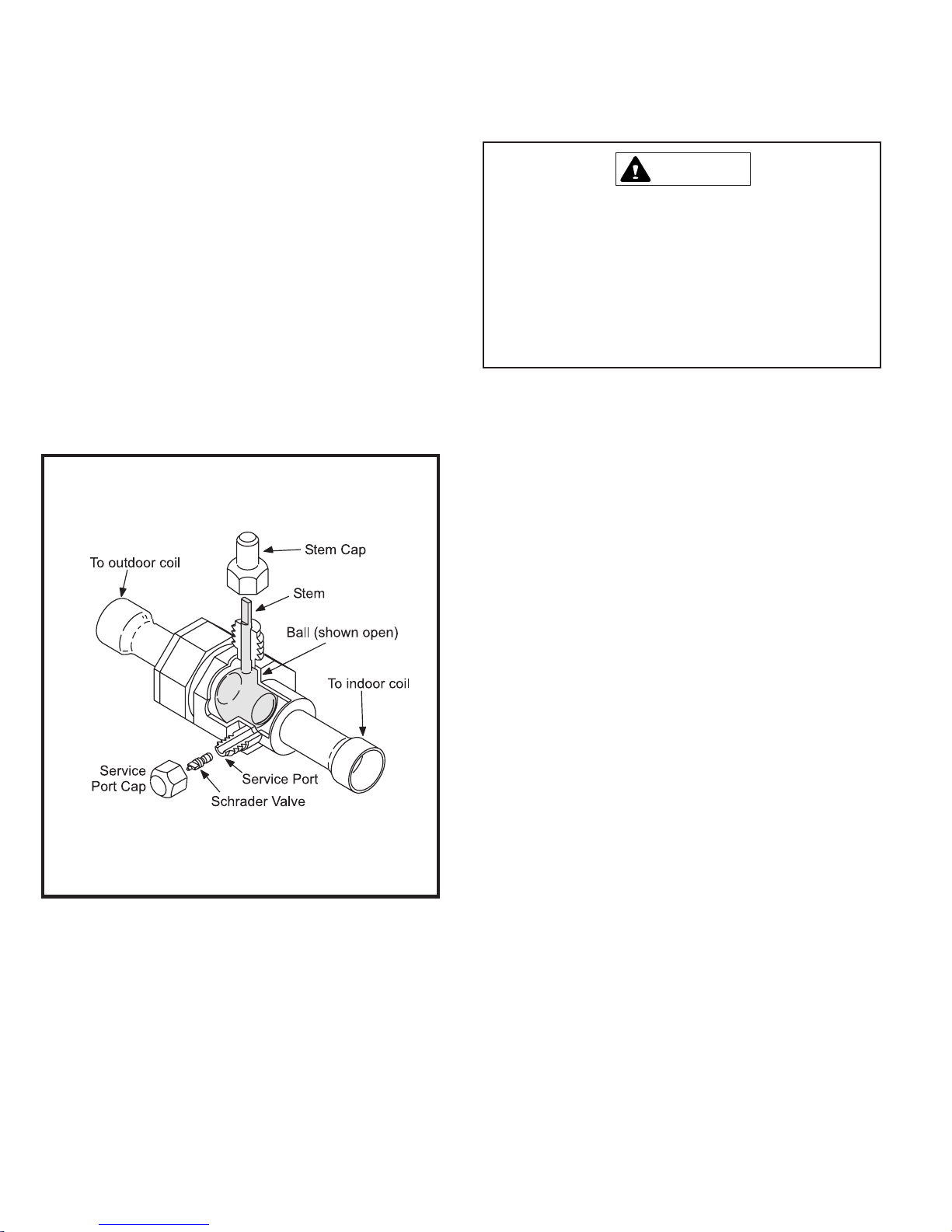
Suction Line (Ball Type) Service Valve
Suctionline(ball type) service valves functionthesameway
astheother valves; thedifferenceis in theconstruction (see
Figure 11).
Manifold Gauge Set
Manifoldgaugesetsusedwithsystemscharged with R410A
refrigerant must be capable of handling the higher system
operating pressures. The gauges should be rated for use
with pressures 0 – 800 on the high side and a low side of
30" vacuum to 250 psi with dampened speed to 500 psi.
Gauge hoses must be rated for use at up to 800 psi of
pressure with a 4000 psi burst rating.
Liquid and Suction Line Service Valves
The liquid line and suction line service valves and service
ports are used for leak testing, evacuating, charging, and
checking charge.
Eachvalveisequippedwithaserviceportwhichhasafactory-
installed Schrader valve (see Figure 10). A service port cap
protectstheSchradervalvefromcontaminationandservesas
the primary leak seal.
To Access the Schrader Port:
1. Remove the service port cap with an adjustable wrench.
2. Connect gauge to the service port.
3. When testing is completed, replace service port cap.
Tighten finger tight, then an additional 1/6 turn.
To Open Liquid or Suction Line Service Valve:
1. Remove stem cap with an adjustable wrench.
2. Useaservicewrenchwithahex-headextensiontoback
thestem out counterclockwise asfaras it willgo.Use a
3/16" hex head extension for liquid line service valves
and a 5/16" extension for suction line service valves.
Metering Device Installation
Figure 9
Figure 10
Service Valve
Valve Closed
Valve Open
Page 10 of 20 506251-01Issue 1015
The ball valve is equipped with a service port with a factory-
installed Schrader valve. A service port cap protects the
Schradervalvefromcontaminationandservesastheprimary
seal.
Leak Testing
After the line set has been connected to the indoor and
outdoor units, the line set connections and indoor unit must
be checked for leaks.
Using an Electronic Leak Detector
1. Connect the high pressure hose of the manifold gauge
set to the suction valve service port. (Normally the high
pressure hose is connected to the liquid line port;
however, connecting it to the suction ports helps to
protectthe manifold gaugesetfrom damage causedby
high pressure.)
2. With both manifold valves closed, connect the cylinder
of R410A refrigerant. Open the valve on the R410A
cylinder(vapor only).
3. Open the high pressure side of the manifold to allow
R410Ainto the linesetand indoor unit.Weighin atrace
amount of R410A. (A trace amount is a maximum of 2
oz. of refrigerant or 3 lbs. pressure.) Close the valve on
the R410A cylinder and the valve on the high pressure
side of the manifold gauge set. Disconnect the R410A
cylinder.
4. Connectacylinderofnitrogenwithapressureregulating
valvetothecenterport of the manifold gaugeset. When
using high pressure gas such as nitrogen for this
purpose, be sure to use a regulator that can control
the pressure down to 1 or 2 psig.
5. Adjustnitrogenpressure to 150psig.Open the valveon
the high side of the manifold gauge set to pressurize
the line set and the indoor coil.
6. After a short period of time, open a refrigerant port to
make sure that an adequate amount of refrigerant has
been added for detection (refrigerant requirements will
vary with lengths). Check all joints for leaks. Purge
nitrogen and R410A mixture. Correct any leaks and
recheck.
Ball Type Service Valve
(Valve Open)
Figure 11
Use adjustable wrench. To open, rotate stem counterclock-
wise 1/4 turn (90°). To close, rotate stem clockwise 1/4 turn
(90°).
Fire, Explosion, and Personal Safety Hazard.
Failure to follow this warning could result in damage,
personal injury, or death.
Never use oxygen to pressurize or purge refrigeration
lines. Oxygen, when exposed to a spark or open flame,
cancause damagebyfireand/oran explosion,thatcould
result in personal injury or death.
WARNING

506251-01 Page 11 of 20Issue 1015
7. Shut off the nitrogen cylinder and remove the manifold
gaugehosefrom the cylinder. Openthe manifoldgauge
valvesto releasethenitrogenfromthe linesetandindoor
unit.
8. Reconnect the manifold gauge to the vacuum pump,
turn the pump on, and continue to evacuate the line set
and indoor unit until 500 microns is maintained within a
20-minute period after shutting off the vacuum pump
and closing the manifold gauge valves.
9. When the requirements above have been met,
disconnect the manifold hose from the vacuum pump.
Openthe service valvesto break thevacuumin the line
set and indoor unit.
Evacuation
Evacuating the system of noncondensables is critical for
proper operation of the unit. Noncondensables are defined
as any gas that will not condense under temperatures and
pressures present during operation of an air conditioning
system. Noncondensables and water vapor combine with
refrigeranttoproducesubstancesthatcorrodecopperpiping
and compressor parts.
Usea thermocouple orthermistorelectronic vacuum gauge
that is calibrated in microns. Use an instrument that reads
down to 50 microns.
Do not use a compressor to evacuate a system. Avoid
deep vacuum operation. Extremely low vacuums can
cause internal arcing and compressor failure. Danger
ofequipment damage.Damagecausedbydeepvacuum
operation will void warranty.
WARNING
1. Connect the manifold gauge set to the service valve
ports as follows:
• Low pressure gauge to suction line service valve
• High pressure gauge to liquid line service valve
2. Connect micron gauge.
3. Connect the vacuum pump (with vacuum gauge) to the
center port of the manifold gauge set.
4. Open both manifold valves and start vacuum pump.
5. Evacuate the line set and indoor unit to a minimum of 500
micronsorlower.Duringtheearlystagesofevacuation,itis
desirabletoclosethemanifoldgaugevalveatleastonceto
determine if there is a rapid rise in pressure.Arapid rise in
pressure indicates a relatively large leak. If this occurs, the
leak testing procedure must be repeated.
6. When 500 microns or lower is maintained, close the
manifold gauge valves, turn off the vacuum pump, and
disconnectthemanifoldgaugecenter port hose from the
vacuum pump. Attach the manifold gauge center port
hose to a nitrogen cylinder with pressure regulator set to
150 psig and purge the hose. Open the manifold gauge
valves to break the vacuum in the line set and indoor
unit. Close the manifold gauge valves.

Page 12 of 20 506251-01Issue 1015
line set. For varying lengths of line set, refer to Table 4 for
refrigerant charge adjustment.
If the system is void of refrigerant, clean the system using
the procedure described below.
1. Use dry nitrogen to pressurize the system and check
for leaks. Repair leaks, if possible.
2. Evacuatethesystemtoremoveasmuchofthemoisture
as possible.
3. Use dry nitrogen to break the vacuum.
4. Evacuate the system again.
5. Weigh the appropriate amount of R410A refrigerant
(listed on unit nameplate) into the system.
6. Monitorthesystemtodetermine the amount of moisture
remaining in the oil. Use a test kit to verify that the
moisture content is within the kit’s dry color range. It
maybenecessarytoreplacethefilterdrierseveraltimes
toachieve therequireddrynesslevel.If system dryness
is not verified, the compressor will fail in the future.
The outdoor unit should be charged during warm weather.
However,applications arise in whichchargingmust occur in
the colder months. The method of charging is determined
by the outdoor ambient temperature.
Measuretheliquidlinetemperatureandtheoutdoorambient
temperature as outlined below:
1. Connect the manifold gauge set to the service valve
ports as follows:
• Low pressure gauge to suction line service valve
START-UP
1. Rotate fan to check for frozen bearings or binding.
2. Inspect all factory and field-installed wiring for loose
connections.
3. Afterevacuation is complete, openliquidlineandsuction
line service valves to release refrigerant charge
(contained in outdoor unit) into system.
4. Replace the stem caps and secure finger tight, then
tighten an additional 1/6 of a turn.
5. Check voltage supply at the disconnect switch. The
voltage must be within the range listed on the unit
nameplate.Ifnot, do notstart equipment untilthepower
companyhasbeen consulted andthevoltagecondition
corrected.
6. Set thermostat for cooling demand, turn on power to
indoor blower and close the outdoor unit disconnect
switch to start the unit.
7. Recheck unit voltage with unit running. Power must be
within range shown on unit nameplate.
Refrigerant Charging
ThissystemischargedwithR410Arefrigerantwhichoperates
atmuchhigherpressuresthanR22.Theliquidlinedrierprovided
with the unit is approved for use with R410A. Do not replace it
withonedesignedforusewithR22.ThisunitisNOTapproved
forusewithcoilswhichuse capillarytubesas arefrigerant
metering device.
R410Arefrigerant cylinders are rosecolored. Refrigerant
should be added through the vapor valve in the liquid
state.
CertainR410Acylinders areidentifiedas being equipped
with a dip tube. These allow liquid refrigerant to be
drawn from the bottom of the cylinder without inverting
the cylinder. Do not turn this type of cylinder upside
down to draw refrigerant.
Units are factory charged with the amount of R410A
refrigerant indicated on the unit rating plate. This charge is
based on a matching indoor coil and outdoor coil with 15'
Ifunit is equippedwitha crankcase heater, itshouldbe
energized 24 hours before unit start-up to prevent
compressor damage as a result of slugging.
CAUTION
Mineral oils are not compatible with R410A. If oil must be
added, it must be a polyol ester oil.
IMPORTANT
Refrigerant Charge Adjustment
* If line length is greater than 15 ft., add this amount.
If line length is less than 15 ft., remove this amount.
Table 4
Liquid Line Set
Diameter
Oz. per 5 ft. adjust
from 15 ft. line set *
3/8 in. 3 oz. per 5 ft.
506251-01 Page 13 of 20Issue 1015
• High pressure gauge to liquid line service valve
2. Close manifold gauge set valves. Connect the center
manifold hose to an upright cylinder of R410A.
3. Ifroomtemperatureisbelow70°F,settheroomthermostat
to call for heat. This will create the necessary load for
properly charging the system in the cooling cycle.
4. Useadigitalthermometer to recordthe outdoor ambient
temperature.
5. When the heating demand has been satisfied, switch
the thermostat to cooling mode with a set point of 68°F.
When pressures have stabilized, use a digital
thermometer to record the liquid and suction line
temperatures.
6. Theoutdoortemperature willdeterminewhich charging
method to use. Proceed with the appropriate charging
method.
Charge Using Weigh-In Method
If the system is void of refrigerant, or if the outdoor ambient
temperature is cool, first locate and repair any leaks then
use the weigh-in method to charge the unit.
1. Recover the refrigerant from the unit.
2. Conduct a leak check, then evacuate as previously
outlined.
3. Weighinthechargeaccordingtothetotalamountshown
on the unit nameplate.
If weighing facilities are not available or if unit is being
charged during warm weather, follow one of the other
procedures outlined below.
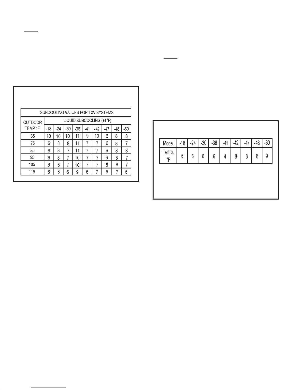
Charge Using Subcooling Method –
Outdoor Temperatures 65°F or Above
When the outdoor ambient temperature is 65°F or above,
the subcooling method can be used to charge the unit.
1. With the manifold gauge hose on the liquid service port
and the unit operating stably, use a digital thermometer
to record the liquid line temperature.
2. At the same time, record the liquid line pressure reading.
3. Use the temperature/pressure chart (Table 5) to
determine the saturation temperature for the liquid line
pressure reading.
4. Subtract the liquid line temperature from the saturation
temperature (according to the chart) to determine
R410A Temperature/Pressure Chart
Table 5
.pmeT F°
e
russerP gisP
238.001
339.201
430.501
531.701
632.901
734.111
836.311
938.511
040.811
143.021
246.221
340.521
443.721
547.921
642.231
746.431
841.731
946.931
052.241
158.441
254.741
351.051
458.251
555.551
652.851
750.161
859.361
957.661
066.961
166.271
265.571
365.871
466.181
563.481
667.781
769.091
861.491
963.791
076.002
179.302
272.702
376.012
.pmeT F°
e
russerP gisP
470.412
574.712
679.022
774.422
870.822
976.132
083.532
180.932
287.242
385.642
483.052
581.452
680.852
780.262
880.662
980.072
091.472
192.872
293.282
395.682
498.092
591.592
694.992
798.303
892.803
997.213
0012.713
1018.123
2014.623
3010.133
4017.533
5015.043
6013.543
7011.053
8010.553
9010.063
0110.563
1110.073
2111.573
3112.083
4114.583
5117.093
.pmeT F°
e
russerP gisP
6110.693
7113.104
8117.604
9112.214
0217.714
1212.324
2218.824
3215.434
4212.044
5219.544
6218.154
7216.754
8215.364
9215.964
0316.574
1316.184
2318.784
3310.494
4312.005
5315.605
6319.215
7313.915
8318.525
9314.235
0410.935
1416.545
2413.255
3411.955
4419.565
5418.275
6418.975
7418.685
8418.395
9410.106
0511.806
1514.516
2517.226
3511.036
4515.736
5510.546
Page 14 of 20 506251-01Issue 1015
_____ ° Liquid Line Temperature °F
_____ ° OutdoorAmbient Temperature °F
_____ ° Approach Temperature °F
–
=
Charge Using Approach Method –
Outdoor Temperatures 65°F or Above
The following procedure is intended as a general guide and
isforuse on expansionvalvesystems only. For bestresults,
indoor temperature should 70°F to 80°F. Monitor system
pressures while charging.
1. Record outdoor ambient temperature using a digital
thermometer.
2. Attach high pressure gauge set and operate unit for
several minutes to allow system pressures to stabilize.
3. Compare stabilized pressures with those provided in
Table 8. Minor variations in these pressures may be
expected dueto differencesin installations. Significant
differences could mean that the system is not
properly charged or that a problem exists with some
componentin the system. Pressureshigherthanthose
listedindicatethat the system is overcharged. Pressures
lower than those listed indicate that the system is
undercharged. Verify adjusted charge using the
approach method.
4. Use the same digital thermometer to check liquid line
temperature.
5. Subtracttheoutdoorambienttemperaturefromtheliquid
subcooling.
5. Comparethesubcoolingvaluewiththoseshown inTable
6. If subcooling is greater than shown, recover some
refrigerant. If subcooling is less than shown, add some
refrigerant.
_____ ° Saturation Temperature °F
_____ ° Liquid Line Temperature °F
_____ ° Subcooling Value °F
–
=
linetemperature todeterminetheapproachtemperature.
6. Comparethe approach valuewiththose shown inTable
7. If the values to do not agree with those provided in
Table 7, add refrigerant to lower the approach
temperature or recover refrigerant from the system to
increase the approach temperature.
Check Charge Using Normal Operating Pressures
Use Table 8 to perform maintenance checks. Table 8 is not
a procedure for charging the system. Minor variations in
these pressures may be due to differences in installations.
Significant deviations could mean that the system is not
properly charged or that a problem exists with some
component in the system.
Approach Values for TXV Systems
Approach value is the liquid line temperature minus the
outdoor ambient temperature (±1°F).
NOTE: For best results, use the same digital thermometer
to check both outdoor ambient and liquid temperatures.
Table 7
Subcooling Values for
TXV Systems
Table 6

506251-01 Page 15 of 20Issue 1015
Normal Operating Pressures
Table 8
L = Liquid S = Suction
Values provided above are typical pressures. Indoor unit matchup, indoor air quality, and indoor load will cause
pressures to vary.

Page 16 of 20 506251-01Issue 1015
OPERATION
Outdoor unit and indoor blower cycle on demand from the
room thermostat. When the thermostat blower switch is
moved to the ON position, the indoor blower operates
continuously.
Maintenance and service must be performed by a qualified
installer or service agency.
Atthe beginning ofeachcooling season, thesystemshould
be checked as follows:
1. Clean and inspect condenser coil. Coil may be flushed
witha water hose.Be sure thepower is offbefore using
water to clean the coil.
2. Outdoor fan motor is pre-lubricated and sealed. No
further lubrication is needed.
3. Visually inspect connecting lines and coils for evidence
of oil leaks.
4. Check wiring for loose connections.
5. Check for correct voltage at unit (with unit operating).
6. Check amp-draw outdoor fan motor.
Unit nameplate _________ Actual _________
NOTE–Ifownercomplainsofinsufficientcooling,the unit
should be gauged and refrigerant charge checked. Refer
to the Refrigerant Charging section on page 12.
Indoor Coil
1. Clean coil, if necessary.
2. Check connecting lines and coils for evidence of oil
leaks.
3. Check condensate pan line and clean, if necessary.
Indoor Unit
1. Clean or change filters.
2. Adjust blower speed for cooling. Measure the pressure
drop over the coil to determine the correct blower CFM.
3. Belt drive blowers: Check belt for wear and proper
tension.
MAINTENANCE
Before performing maintenance operations on system,
turn the electric power to unit OFF at disconnect
switch(es). Unit may have multiple power supplies.
Electrical shock could cause personal injury or death.
WARNING

506251-01 Page 17 of 20Issue 1015
4. Check all wiring for loose connections.
5. Check for correct voltage at unit (with unit operating).
6. Check amp-draw on blower motor.
Unit nameplate _________ Actual _________
Start-Up and Performance Checklist
Job Name _______________________________ Job No. ________________ Date ______________
Job Location _____________________________ City ___________________ State ______________
Installer _________________________________ City ___________________ State ______________
Unit Model No.______________ Serial No. ___________________
Service Technician ________________________________________ Nameplate Voltage ______________
Rated LoadAmpacity ________ Compressor _______________ Outdoor Fan ___________________
Maximum Fuse or Circuit Breaker________________________
Electrical Connections Tight? Indoor Filter Clean? Supply Voltage (Unit Off) ________________
Indoor Blower RPM _____________ S.P. Drop Over Indoor (Dry) ____________
Outdoor Coil EnteringAir Temperature _____________ Voltage with Compressor Operating _____________
Discharge Pressure___________ Vapor Pressure ____________
Refrigerant Charge Checked? Outdoor Fan Checked?
Refrigerant Lines: Leak Checked? ProperlyInsulated?
Service Valves: Fully Opened? Caps Tight?
Thermostat: Calibrated? ProperlySet? Level?

Page 18 of 20 506251-01Issue 1015
Figure 12
HCF
1
DESCRIPTION
KEY COMPONENT
A4 CONTROL - TIMED OFF
B1 COMPRESSOR
B4 MOTOR - OUTDOOR FAN
C12 CAPACITOR - DUAL
HR1 HEATER - COMPRESSOR
K1-1 CONTACTOR - COMPRESSOR
S4 SWITCH - HIGH PRESSURE
S24 SWITCH - LOSS OF CHARGE
FOR USE WITH COPPER CONDUCTORS ONLY. REFER TO UNIT RATING
PLATE FOR MINIMUM CIRCUIT AMPACITY AND MAXIMUM OVERCURRENT
PROTECTION SIZE.
WARNING--
ELECTRIC SHOCK HAZARD, CAN CAUSE INJURY OR DEATH.
UNIT MUST BE GROUNDED IN ACCORDANCE WITH NATIONAL
AND LOCAL CODES.
OUTDOOR
FAN
FCH
1
23
RSC
C
2
3
1
EQUIPMENT
GROUND
HR1
L2
208-230/60/1
L1
K1-1
BLACK
YELLOW
RED
RED
C12
BLACK
ORANGE
B4
PURPLE
K1
S4 S24
A4
CY1
TO 24 VAC
POWER SOURCE
20 VA MINIMUM
NEC CLASS 2
S4 HIGH
PRESSURE
SWITCH
(IF USED)
S24 LOSS
OF CHARGE
SWITCH
(IF USED)
B1
GROUND
LUG
GROUND
L2
L1
208-230/60/1
CY1
TO 24 VAC
POWER SOURCE
20 VA MINIMUM
NEC CLASS 2
A4
TIMED OFF
CONTROL
(IF USED)
DUAL
CAPACITOR
RED
COMPRESSOR
CONTACTOR
BLACK
COMPRESSOR
CRANKCASE HEATER
(IF USED)
PURPLE
BLACK
ORANGE
RED
YELLOW
SR
LINE VOLTAGE FACTORY INSTALLED
1
LINE VOLTAGE FIELD INSTALLED
24 VOLT FACTORY INSTALLED
CLASS II VOLTAGE FIELD INSTALLED
Wiring Diagram P/N 48352-001

506251-01 Page 19 of 20Issue 1015
ALLIED AIR ENTERPRISES
EQUIPMENT LIMITED WARRANTY
APPLIES IN U.S.A.AND CANADAONLY
FAILURE TO MAINTAIN YOUR EQUIPMENT WILL VOID THIS WARRANTY
COVERED EQUIPMENT
The following Allied Air Enterprises heating and cooling equipment is covered by the Limited Warranty,
Condensing Units: 2SCU13, 4SCU13, 4SCU14, 4SCU16, 4SCU18, 2AC13, 2AC14, 4AC13, 4AC14
Heat Pumps: 2SHP13, 4SHP13, 2SHP14, 4SHP14, 4SHP16, 4SHP18, 2HP13, 2HP14, 4HP13, 4HP14
Gas Furnaces: G1N80, G1D80, G2D80, G1D91, G1D93, G2D93, G2D95, FPBB, CG80, CG90, CG92, CG93, CG95
Oil Furnaces: LBR80, LBF80, LHF80, LUF80, LHR80, RLUF, RLBF, RLBR, RLBU, RLHF, RLHR
Electric Furnaces: EFC, EFV
Evaporator Coils: EC, EU, EH, EM
Air handlers: BCS2, RBCS2
Package Equipment: 2PCE13, 4PCE13, 4PCE15, 2PGE13, 4PGE13, 4PGE15, 2PHP13, 4PHP13, 4PHP15, 2SG13, 2SH13, 2SA13, RGE13, RPGE13, RHP13, RCE13, RPHP13, RPCE13
PARTS and COMPRESSOR COVERAGE
The covered equipment, parts and compressor are warranted byAllied Air for a period of five (5) years from the date of the original installation, when installed in a residential application (which includes
homes, duplexes, apartments and condominiums). For non-residential applications, the covered equipment and parts are warranted for a period of one (1) year and compressor is warranted for five (5)
years from the date of the original installation. If, during this period, a covered component fails because of a manufacturing defect, Allied Air will provide a free replacement part to the owner through a
licensed service contractor utilizing an Allied Air distributor. The purchaser must pay shipping charges and all other costs of warranty service. Allied Air will not pay labor involved in diagnostic calls or
in removing, repairing, servicing or replacing parts. Such cost may be covered by a separate warranty provided by the installer.
HEAT EXCHANGER EXTENDED COVERAGE
All covered heat exchangers are warranted by Allied Air for a period of twenty (20) years from the date of original installation, when installed in a residential application. Heat exchangers in all non-
residential applications are warranted for a period of ten (10) years.
Heat Exchanger Availability: If a replacement heat exchanger is no longer available for a unit covered by this Limited Warranty, Allied Air will allow a credit toward the purchase of an equivalent Allied
Air furnace (at the current suggested distributor’s cost).
NOTE: If the date of original installation cannot be verified, the warranty period will be deemed to begin ninety (90) days after the date of manufacture.
EXCLUDED COMPONENTS
The following components are expressly not covered by this Limited Warranty: cabinets, cabinet pieces, air filters, driers, refrigerant, refrigerant line sets, belts, wiring, fuses, oil nozzles, unit accessories
and any parts not affecting unit operation
CARE OF EQUIPMENT
All new Allied Air units must be properly installed, operated and maintained in accordance with the unit installation, operation and maintenance instructions provided with each Allied Air unit. Failure to
maintain the equipment per Allied Air instructions will void this Limited Warranty.
WARRANTY PROCEDURE
When service or warranty parts are required:
1. Call a local licensed service dealer or contractor.
2. If the installing dealer is unable to provide warranty service, check online at www.alliedair.com.
3. Be prepared to furnish the following information:
a. complete model and serial number;
b. proof of required periodic maintenance, installation date and location; and
c. an accurate description of the problem.
WARRANTY LIMITATIONS
1. This Limited Warranty is void if the covered equipment is removed from the original installation site.
2. This Limited Warranty does not cover damage or defect resulting from:
a. flood, wind, fire, lightning, mold, or installation and operation in a corrosive atmosphere, or otherwise in contact with corrosive materials (chorine, fluorine, salt, recycled waste water, urine,
fertilizers, or other damaging substances or chemicals); accident, or neglect or unreasonable use or operation of the equipment including operation of electrical equipment at voltages other
than the range specified on the unit nameplate (includes damages caused by brownouts);
b. modification, change or alteration of the equipment, except as directed in writing by Allied Air;
c. operation with system components (indoor unit, outdoor unit and refrigerant control devices) which are not an ARI match or meet the specifications recommended by Allied Air;
d. operation of furnaces with return air temperatures of less than 60ºF (16ºC) or operation of a furnace field installed downstream from a cooling coil; and
e. use of contaminated refrigerant or refrigerant not compatible with the unit.
The installation of replacement parts under the terms of this Limited Warranty does not extend the original warranty period.
Allied Air makes no express warranties other than the Limited Warranty specified above. All implied warranties, including the implied warranties of merchantability and fitness for a
particular purpose, are excluded to the extent legally permissible. Should such exclusion or limitation of this Limited Warranty be unenforceable, such implied warranties are in any event
limited to a period of one (1) year. Liability for incidental and consequential damages is excluded. Some states do not allow limitation of incidental damages, so these limitations or
exclusions may not apply to you. Allied Air will not pay electricity or fuel costs, or increases in electricity or fuel costs, for any reason whatsoever, including additional or unusual use of
supplemental electric heat. This Limited Warranty does not cover lodging expenses or labor charges.
Allied Air shall not be liable for any default or delay in performance under this Limited Warranty caused by any contingency beyond its control.
This Limited Warranty gives you specific legal rights, and you may also have other rights which vary from state to state.
NOTE TO CUSTOMER:
Please complete information below and retain this warranty for your records and future reference.
Outside Unit Model Number: ____________________________________________________ Serial Number: _______________________________________ Installed Date: __________________
Furnace / Air Handler: _________________________________________________________ Serial Number: _______________________________________ Installed Date: __________________
Indoor Coil Model Number: _____________________________________________________ Serial Number: _______________________________________ Installed Dare: __________________
Installing Company Name: ___________________________________________________________________________________ Phone: _______________________________________________
Installing Company Address: _____________________________________________________________ State/Province: _______________________________ Zip/Postal Code: _______________
215 Metropolitan Drive - West Columbia - SC - 29170
© 2008 Allied Air Enterprises Litho U.S.A. FORM W-2008-2 (9/25/2009)

Page 20 of 20 506251-01Issue 1015
AlliedAirEnterprises Inc. (“AlliedAir”)providesitsairconditioningandheating productswitha Standard LimitedPartsWarrantyfor five (5) years. Thisadditional5-YearLimitedExtended
PartsWarrantyisinadditionto and is intended to supplementAlliedAir’sStandardLimitedPartsWarranty. As such,AlliedAir provides fora totalof10-yearsoflimitedwarrantycoverage
(Standard Limited Parts Warranty plus additional 5-Year Limited Extended Parts Warranty).
This 5-Year Limited Extended Parts Warranty applies only to the original purchaser of the equipment and cannot be transferred. If during the coverage period, a covered part fails
becauseofadefect in materials or workmanshipundernormaluseandmaintenance,AlliedAir will provideafreereplacementparttothepurchaserthroughalicensed service contractor
utilizing an authorizedAlliedAir distributor. The purchaser must pay shipping costs and all other costs of warranty service. AlliedAir will not pay labor involved in diagnostic calls or in
removing, repairing, servicing or replacing parts. EXTENDED COVERAGE -
PARTS/COMPRESSORS
Covered equipment and parts are warranted byAlliedAir for a total of 10 YEARS (Standard Limited Parts Warranty) from installation, except as provided below
HEAT EXCHANGERS
Covered residential heating equipment’s heat exchanger is warranted byAlliedAir for a LIMITED LIFETIME from date of original installation, except as provided below.
EXCLUDED COMPONENTS -
The following components are expressly not covered by this 5-Year Limited Extended Parts Warranty: cabinets, cabinet pieces, air filters, driers, refrigerant, refrigerant line sets, belts,
wiring, fuses, oil nozzles, unit accessories, R-22 compressors, and any parts not affecting unit operation.
If this 5-Year Limited Extended Warranty does not apply, then parts are warranted under the Standard Limited Parts Warranty for a period of 5 YEARS and heat exchangers for 20
YEARS. If the Standard Limited Parts Warranty periods differ from the original warranty certificate, the periods stated on the original warranty certificate apply.
This 5-Year Llimited Extended Parts Warranty does not apply to, and no warranty is offered byAlliedAir, on any unit ordered over the internet. Proof of purchase may be required.
Anypartreplacedpursuanttothis 5-YearLimitedExtended PartsWarranty is warranted onlyfortheunexpiredportion of thelimitedextendedwarrantyterm remaining for theoriginalpart.
The installation of replacement parts under the terms of this 5-Year Limited Extended Parts Warranty does not extend the warranty period.
Steps for obtaining replacement parts under this 5-Year Limited Extended Parts Warranty:
If you suspect a defect in your equipment, please contact the installer of the unit to obtain assistance. If unsuccessful, please contact anAllied Air dealer or distributor in
your area. If unable to obtain local assistance, refer toAlliedAir’s website (www.alliedair.com) or contact AlliedAir at 800-448-5872.
Allied Air is specifically not responsible for:
1.Damageor repairs required asaresultof flood, fire, wind,lighteningstrike(to the home orunit),corrosiveatmosphere, contact with corrosivematerial (chlorine,fluorine,salt,recycled
waste water, fertilizers or other damaging substances) or other conditions beyond the control ofAlliedAir;
2. Use of parts, accessories, or refrigerant not compatible with the unit;
3. Modification, change or alteration of the unit, except as expressly directed in writing byAllied Air;
4. Improper use, accident, neglect or unreasonable use or operation of the unit, including operation of electrical equipment at voltages other than the range specified on the unit
nameplate;
5. Operation with system parts (indoor unit, outdoor unit and refrigerant control devices) which are notARI matched or do not meet the specifications recommended byAlliedAir;
6. Damage or repairs required as a consequence of faulty or installation or application;
7. Normal maintenance as described in the installation and operating manual, such as cleaning of coils, filter cleaning and/or replacement and lubrication; and
8. Changes in the appearance or sound of the unit that do not affect its performance.
This 5-Year Limited Extended Parts Warranty is an extension ofAlliedAir’s Standard Limited Parts Warranty. ANY IMPLIED WARRANTY OF MERCHANTABILITY OR FITNESS FOR
APARTICULAR PURPOSE ON THIS PRODUCT IS LIMITED IN DURATION TO THE TERM OF THIS LIMITED EXTENDED WARRANTY. Some states and provinces do not allow
limitations on how long an implied warranty lasts, so the above limitation may not apply to you.
ALLIED AIR SHALL IN NO EVENT BE LIABLE FOR INCIDENTAL OR CONSEQUENTIAL DAMAGES, INCLUDING BUT NOT LIMITED TO EXTRA UTILITY EXPENSES OR
DAMAGES TO PROPERTY. Some states and provinces do not allow the exclusion or limitation of incidental or consequential damages, so the above limitation or exclusion may not
apply to you
The parties intend this writing as a final expression of their agreement with respect to warranties. Allied Air makes no other warranty beyond that which is expressly
contained in this writing.
AlliedAir shall not be liable for any default or delay in performance under this warranty caused by any contingency beyond its control, including the unavailability of replacement parts.
This warranty gives you specific legal rights, and you may also have other rights that vary from state to state or province to province.
1 Excludes residents of states or provinces where registration requirements are prohibited, such as California and Quebec. Residents of these states or provinces may either register as noted above or
provide proof of when the unit was purchased and installed, such as an original invoice from the contractor with the Owner’s name, address, purchase date, serial and model number.
5-YEAR LIMITED EXTENDED PARTS WARRANTY
1. The unit is anArmstrongAir, Air ease, Ducane, or Concord branded unit;
2. The unit is installed in a residential application, which is an owner-occupied single-family residence. No commercial applications are allowed;
3. The unit is properly registered at www.alliedair.com with Allied Air within 60-days after the original date of installation or occupancy.1To
register, follow the directions and complete the online warranty registration at www.alliedair.com. For customer inquiries, contactAllied Air at
1-800-448-5872.
4. The unit is part of a completeARI matched system and installed by a state certified or licensed contractor in accordance with the unit installation, operation,
and maintenance instructions provided with the unit.
5. Coils and air handlers are covered only when they are branded Armstrong,AirEase, Ducane, Concord or ADPand are purchased and newly installed as a
system along with a qualifying unit. Except forADP-branded products, coverage of other third party coils and air handlers are specifically excluded from
this 5-Year Limited Extended Parts Warranty.
6. Installation of the unit takes place on or after October 3, 2008.
REQUIREMENTS FOR EXTENDED COVERAGE-
Table of contents
Other Allied Air Air Conditioner manuals


Popular Air Conditioner manuals by other brands

Mitsubishi Electric
Mitsubishi Electric MSZ-GE60VAD operating instructions

Nipon Coolair
Nipon Coolair MB18 GA Installation and user manual

Danfoss
Danfoss Optyma OP-LPHE Series instructions

Adler Europe
Adler Europe AD 7915 user manual

LG
LG LP073HDUC/00 owner's manual

Fujitsu
Fujitsu AU A30LBLU Series Design & technical manual

Honeywell
Honeywell MP09 Series user manual

Mitsubishi Electric
Mitsubishi Electric PQRY-P200YEM-A Service handbook

LG
LG ATNH243PLAE Service manual

Fujitsu
Fujitsu ASYG09KMCB Design & technical manual

DeLonghi
DeLonghi PAC N135E instruction manual

Mitsubishi Heavy Industries
Mitsubishi Heavy Industries SRK63ZTL-W user manual


