Allstyle AB Series User manual

AB* SERIES
AIR HANDLING UNITS INSTALLATION GUIDE
GENERAL
The AB* Series is designed for horizontal recessed
installations in a furred down area, above a suspended
ceiling or recessed in the ceiling. AB* Series models
are for electric heat, DX cooling, and for heat pump
applications. The unit can be congured for return air
ow through the integral access panel or at the end
of the unit. Installation tabs are built into the cabinet
to facilitate mounting the unit. Optional panels are
available that allow a wide range of installation
options. Electric resistance heaters are available
along with optional air conditioning and heat pump
indoor coils. Full service of all components is easily
accomplished through the access panels.
Coil Company, L.P
WARNING: Due to possible damage to equipment or personal injury, installation, service, and
maintenance should only be performed by a trained, qualied person. Consumer service is recommended
only for lter replacement.
Installation of this unit shall be made in accordance with the National Electric Code, NFPA
No. 90A and 90B, and any other local codes or utilities requirements.
WARNING: HAZARDOUS VOLTAGE - Ensure all power is disconnected before installing or
servicing this unit. More than one disconnect device may be required to de-energize the equipment.
Hazardous voltage can cause severe personal injury. Make certain all panel are in place before operating
this unit.
UNPACKING
Carefully unpack the unit and inspect the contents for
damage. If any damage is found at the time of delivery,
proper notication and claims should be made with the
carrier who delivered the unit.
Check the rating plate to assure model number and
voltage, plus any kits agree with what you ordered.
The manufacturer should be notied within 5 days of
any discrepancy or parts shortage.
LOCATION
The blower coil unit should be centrally located and
may be installed above a suspended ceiling with the
integral return panel, in a furred down area with remote
or integral return, or recessed in the ceiling.
This unit is approved for “0” clearance from any side,
front, rear, or duct work. The unit must be installed in a
level position to ensure proper condensation drainage.
Make sure the unit is level in both directions within 1/8”.
1/2018 LM20020-D

INSTALLATION GUIDE
The unit incorporates installation tabs that mount to the
framing and provide a 1/2” ange to trim to the nished
edge of a sheet rock ceiling. The access panel mounts
to the cabinet and trims the installation.
All service entrances and exits on the cabinet are
recessed to allow for 2” x 4” framing of the opening the
cabinet will be centrally located within. Any modications
to existing framing should be accomplished by the
general contractor to ensure structural strength is
maintained in the structural opening in the framing for
the ABF Series should be 47 1/4” long and 22 3/4” wide.
The unit should be positioned where the bottom edge of
the cabinet is 1/2” below the framing member.
DUCT WORK
The duct work should be installed in accordance with
the NFPA No. 90A “Installation of Air Conditioning and
Ventilating Systems” and No. 90B “Residential Type
Warm Air Heating and Air Conditioning Installed”.
The duct work should be insulated in accordance with
the applicable requirements for the particular type
installation as required by HUD, FHA, VA the applicable
building code, local utility, or other governing body.
CONDENSATE DRAIN
The AB* Series furred down air handlers are now
shipped standard with our integral drain trap built
into the drain pan. This unique design eliminates the
need for exterior condensate traps in the primary drain
line. Do not reduce the drain line size less than the
connection size on the drain pan. Condensate should
be piped to an open drain or to the outside. All drains
must pitch downward away from the unit a minimum of
1/8” per foot of line to ensure proper drainage.
REFRIGERANT PIPING
Refrigerant pipe connections are located within the
unit cabinet. Holes are provided to route refrigerant
pipes from either side of the cabinet. Refrigerant piping
external to the unit shall be sized in accordance with
the instructions of the manufacturer of the outdoor
equipment. When units are recessed mounted in the
wall, make certain that piping connections are pressure
tested prior to the wall being closed.
Manufacturer does not insulate the expansion valve
distributor tubes or liquid lines coming from
manifold. It is the sole responsibility of the contractor
to properly insulate from condensation.
(YOU MUST INSULATE THE REFRIGERANT LINES
AND TXV UP TO WHERE THE PAN CATCHES ALL
CONDENSATE DRIPS)
METERING DEVICE
All units are shipped with a check ow piston installed which
is designed for air conditioning or heat pump operation.
If your application requires a thermal expansion valve or
check expansion valve then it is necessary to remove the
piston from the distributor assembly and install the proper
metering device. Be sure to follow the instructions in the
kit to ensure proper installation.
WIRING
Consult all schematic and pictorial wiring diagrams of this
unit and the outdoor equipment to determine compatibility
of the wiring connections and to determine specic
requirements.
All eld wiring to the blower coil should be installed in
accordance with the latest edition of the National Electric
Code NFPA No. 70 and any local codes.
Check rating plates on unit for rated volts, minimum
circuit ampacity and maximum over current protection.
Supply circuit power wiring must be 75°C. (167°F)
minimum copper conductors only. Copper supply wires
shall be sized to the National Electric Code or local code
requirements, whichever is more stringent.
The unit is shipped wired for 230/240 Volt AC, 60 Hz, 1
Phase Operation. If the unit is to be operated at 208 VAC,
60 Hz, then follow the instruction on the indoor unit wiring
diagram to change the low voltage transformer to 208
VAC operation.
Be sure the unit is properly grounded.
Class 2 low voltage control wiring should not be run in
conduit with power wiring and must be separated from
power wiring, unless class 1 wire of proper voltage rating
is used. Low voltage control wiring should be 18 Awg,
color coded (105°C minimum). For lengths longer than
100 ft., 16 Awg wire should be used. Make certain that
separation of control wiring and power wiring has been
maintained.
AB* SERIES INSTALLATION GUIDE Page 2

INSTALLATION GUIDE
AB* SERIES INSTALLATION GUIDE Page 3
THERMOSTAT
Select a thermostat that is commonly referred to as a
single stage cooling with electric sub base. This stat
will energize the fan on a demand for heat or cool.
Install the thermostat on an inside wall away from
drafts, lights or other heat sources in a location that
has good air circulation from the other rooms being
controlled by the thermostat. The thermostat should
be mounted 4’ to 5’ above the oor.
SEQUENCE OF OPERATION
Cooling (cooling only or heat pump with reversing
valve energized in heat mode): When the thermostat
calls for cooling, the blower relay is energized. The
N.O. contacts will close after a time delay then the
indoor blower will operate. The circuit between R and
Y is completed which causes the contactor on the
outdoor equipment to close, and start the compressor
and the outdoor fan motor.
Cooling (heat pump with reversing valve energized
in cooling mode): When the thermostat calls for
cooling, the circuit between R and G and R and O is
complete. Circuit R and O energizes the reversing
valve to the cooling position. Circuit R and G energizes
the blower relay. The N.O. contacts will close after a
time delay then the indoor blower will operate. The
circuit between R and Y is complete. Which causes
the contactor on the outdoor equipment to close, and
start the compressor and the outdoor fan motor.
Heating (electric heat only): When the thermostat
calls for heat, the circuit between R and W is completed.
The heat sequencer is energized. A time delay will
occur, which allows the heating element(s) and the
indoor blower motor to come on.
Heating (heat pump reversing valve energized
in the heat mode): When the thermostat calls for
heat, the circuits between R and B, R and Y and R
and G are completed. Circuit R and B energize the
reversing valve switching it to the heat position. Circuit
R and Y energized the outdoor unit contactor starting
the compressor and outdoor fan. Circuit R and G
energizes the blower relay stating the blower motor.
If the indoor room temperature should continue to fall,
circuit R and W2 is by the second-stage heat bulb
on the thermostat. Circuit R-W2 energizes the heat
sequencer. The completed circuit will energize the
supplemental electric heat.
Blower Time Delay: This unit is equipped with timed
on and a timed off relay. This relay delays the start
and delays the stopping of the indoor fan motor to
maximize the efciency of the unit.
Defrost: When the unit starts the defrost cycle
supplemental heat can be provided by connecting B
on the blower coil to the defrost relay on the outdoor
heat pump. This will complete the circuit between R
and B (in the blower coil) through a set of contacts in
the defrost relay in the outdoor unit. This circuit when
it is connected, will help prevent cold air from being
discharged from the indoor unit during the defrost.
BLOWER
Units through three tons are supplied with a multi-
speed motor (high, medium, and low) with a direct
drive blower wheel which can obtain various air ows.
One and one and a half ton units are factory wired on
low speed, two ton units are factory wired on medium
speed, and two and half ton units are factory wired and
shipped with the blower connected for high speed. If
a lower blower speed is required, disconnect all power
to the unit, remove the factory wired indoor fan motor
lead from the fan relay and place an insulated cap
on the removed motor lead. Remove the insulated
cap from the desired indoor fan motor lead, place a
spade connector on the lead and connect it to the fan
relay where the original lead was connected. The
black motor lead is high speed, the red motor lead
is low speed, and the blue motor lead (if available) is
medium speed. Be sure to check the air ow and the
temperature drop across the evaporator coil to ensure
that you have sufcient air ow. For ECM option refer
to ECM wiring diagram for speed tap placement.
(ECM speed taps are 24v to energize) See page 8.
START UP
Once all connections are complete the unit should be
started up , and a check out of the completed system
should be performed. Before performing any system
test, make sure that all grilles, registers, and dampers
are open and set to the correct position. Also make
certain that the air lter is installed in the return air prior
to running the air handler.
A performance test should be conducted in the
accordance with the outdoor equipment manufacturer’s
instructions. Airow tests should be conducted in the
heating and cooling modes to ensure satisfactory
operation.

INSTALLATION GUIDE
MAINTENANCE
The system air lter(s) should be inspected, cleaned or
replaced at least monthly. If the lter is mounted internal
to unit, make sure that electrical power is disconnected
before removing the access panels. Make certain that
the access panels are replaced and secured properly
before placing the unit back in operation. This product
is designed for dependable service, however periodic
maintenance should be scheduled to be conducted by
trained professional service personnel. This service
should be conducted at least annually, and should
include testing and inspection of electrical and refrigerant
components. The heat transfer surface should be
cleaned. The blower motor is permanently lubricated for
normal operating conditions.
AB* SERIES INSTALLATION GUIDE
Warnings
Do not store or use any corrosives or
combustibles in the vicinity of this unit. All
panels must be in place and properly secured
before operating this equipment.
All electrical power servicing this unit must be
disconnected prior to removal of any panels.
Service of this unit must be accomplished
by qualied trained professional personnel
only.
Page 5
NOTE:
The condensate drain pan shown in Figure 1, has
an adjustment strap to ensure proper condensate
removal. The strap is identied by the arrow in the
gures. If it is found to be necessary, the strap may
be easily loosened and refastened to change the
pitch in the drain pan toward the drain outlets. The
drain pan pitch should not exceed 1/2 of an inch. For
proper drain line connections, follow instructions
from “CONDENSATE DRAIN” on Page 2.
WARNING
Warranty will be voided if any chemical products are used on any AllStyle coils.
AllStyle suggests water, and a soft bristled brush for cleaning.
Figure 1: Drain Pan Adjustment Strap

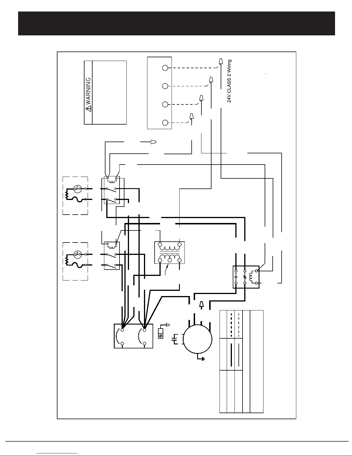
WIRING DIAGRAM
AB* SERIES INSTALLATION GUIDE Page 6
Revision of new relay board as of July 2016
USE COPPER CONNECTORS ONLY.
Use Conductors Suitable for 167 Deg F.
208-230VAC / 60Hz / 1Ph
EQUIPMENT GROUND USE COPPER OR
ALUMINUM WIRE.
Orange
FACTORYWIRING TABLE
HIGH VOLTAGE WIRING
LOW VOLTAGE WIRING
Single Speed Fan Control
Connect Only One Fan Lead
Not all models have 3 speeds
Black - High Speed
Blue - Medium Speed
Red - Low Speed
Air Handler with (AHF, AHK)
GND
L1
L2
M3 M4
M1 M2
Black
Red
Black
Purple
Brown
White
Black
Blue
Black
Blue
DISCONNECT POWER BEFORE
INSTALLATION OR SERVICING.
MULTIPLE POWER SOURCES
MAY BE PRESENT.
FAILURE TO DO SO MAY
CAUSE PROPERTY DAMAGE,
PERSONAL INJURY, OR DEATH.
Red
*AW1606-55361-B*
*AW1606-55361-B*
Blue
Black
Blue
Purple
Orange
Blue
Blue
Brown
White
White
Blue
ELEMENT
HEATER
NOTE 1) Wiring change is required to convert transformer to
208 Volts. Disconnect power. Disconnect orange high
voltage lead and place on terminal labeled as "208V" for 208
Volts power.
NOTE 2) Brown and White wires are used with Heat Kits
only.
FIELD
CONSULT NATIONAL CODE FOR PROPER WIRE SIZE.
3, 5kW Heating Elements
AW1606-55361-B
LIMIT
FUSE
LINK
HEATER
RELAY
2 4
65
1 3
FAN RELAY
2 4
65
1 3
G R C W
THERMOSTAT
INDOOR
MOTOR
Purple
Brown
White
TRNSF
24V
230V
208V
Com
SEE NOTE 2
Red
Blue
Black
Red
Black
Brown/White
Brown
Green
Purple
Red
24V CLASS 2 Wiring
Red Blue
SEE
NOTE 1
Blue
White
CIRCUIT NO. 1
208-230/60/1
AB* Series
WIRING DIAGRAM
Page 7AB* SERIES INSTALLATION GUIDE
24V
W G R C
THERMOSTAT
Use Conductors Suitable for 167 Deg F.
Green
Red
Purple
TRANSFORMER
USE COPPER CONNECTORS ONLY.
EQUIPMENT GROUND USE COPPER
208-230VAC / 60Hz / 1Ph
OR ALUMINUM WIRE.
230V
208V
Com
SEE
NOTE 1
NOT ALL MODELS USE FUSE LINKS
Single Speed Fan Control
Connect Only One Fan Lead
Not all models have 3 speeds
Black - High Speed
Blue - Medium Speed
Red - Low Speed
Air Handler (AHF, AHK) with
AW1606-55362-B
6, 8, 10kW Heating Elements
Red
GND
L1
L2
ELEMENT
HEATING
Brown
White
DISCONNECT POWER BEFORE
INSTALLATION OR SERVICING.
MULTIPLE POWER SOURCES
MAY BE PRESENT.
FAILURE TO DO SO MAY
CAUSE PROPERTY DAMAGE,
PERSONAL INJURY, OR DEATH.
FACTORY WIRING
NOTE 1) Wiring change is required to convert transformer to 208 Volts.
Disconnect power. Disconnect orange high voltage lead and place on
terminal labeled as "208V" for 208 Volts power.
WIRING TABLE
HIGH VOLTAGE WIRING
LOW VOLTAGE WIRING
FIELD WIRING
CONSULT NATIONAL CODE FOR PROPER WIRE SIZE.
*AW1606-55362-B*
TERMINAL BLOCK/
208-230/60/1
CIRCUIT NO.1
DISCONNECT
M4
M3
M2
M1
Black
Blue
Black
Blue
Yellow
Blue
FUSE
LIMIT
LINK
FUSE
LINK
Green
Blue
Orange
Blue Blue
Black
Black
Blue
LIMIT
ELEMENT
HEATING
White
M4
M3
M2
M1
Black
*AW1606-55362-B*
2 4
65
1 3
FAN RELAY
2 4
65
1 3
INDOOR
MOTOR
Purple
Red
Blue
Red
Black
Brown/White
Brown
Red
Green
Green
Purple
Blue
White
Black
Blue
Black
Black
Revision of new relay board as of July 2016

WIRING DIAGRAM
L1 L2 GND
W G R C Y
THERMOSTAT
Green
Red
Purple
TRANSFORMER
24V
TERMINAL
BLOCK
FACTORY WIRING
NOTE 1) Wiring change is required to convert transformer to 208 Volts.
Disconnect power. Disconnect orange high voltage lead and place on
terminal labeled as "208V" for 208 Volts power.
WIRING TABLE
HIGH VOLTAGE WIRING
LOW VOLTAGE WIRING
FIELD WIRING
USE COPPER CONNECTORS ONLY.
Use Conductors Suitable for 167 Deg F.
208-230VAC / 60Hz / 1Ph
EQUIPMENT GROUND USE COPPER OR
ALUMINUM WIRE.
DISCONNECT POWER BEFORE
INSTALLATION OR SERVICING.
MULTIPLE POWER SOURCES
MAY BE PRESENT.
FAILURE TO DO SO MAY
CAUSE PROPERTY DAMAGE,
PERSONAL INJURY, OR DEATH.
230V
208V
Com
CONSULT NATIONAL CODE FOR PROPER WIRE SIZE.
AW1509-55363-B
Air Handler - No Heat
SEE
NOTE 1
Black
Black
Black
Red
Yellow
Yellow
Purple
Green
With CTM Control
Com
L2 L1
Cool
Heat
Cool
CTM CONTROL
Heat
24V
Com
CTM
MOTOR
Orange
Blue
Black
Purple
White
Blue
Red Yellow
Red
Red
Black
G C R
FAN TIMER
COM
NC
NO
Blue
Black
Red
Blue
Blue
Red
Red
Page 8AB* SERIES INSTALLATION GUIDE

PRODUCT FEATURES
• Designed for Installation in a Furred Down Area or Dropped Ceiling Area
• Cooling Only, Cooling and Electric Heating, or Heat Pump with Electric Back Up
• Optional Factory Installed Electric Heat of Either 3, 5, 6, 8, or 10 kW
• Cooling Capacities 1, 1.5, 2.0, 2.5, or 3.0 Nominal Tons
• Orice Refrigerant Metering is Standard with ermal Expansion Valves Optional
• Standard Integral Drain Trap
• Pre-Punched Side Mounting Tabs for Easier Installations
• Copper Tube Option
• Long Life Aluminum Tubing, Fins and End Plates
• Powder Coated, Hinged Access Panels with Filter Rack
• Fully Insulated Embossed, Galvanized Steel Cabinets
AB* SERIES
FURRED DOWN
AIR HANDLER
Coil Company, L.P
Cabinet Dimensions
Model
Nominal
Tonnage
Cabinet
Height
A
Cabinet
Length
B
Cabinet
Width
C
Plenum
Height
D
Plenum
Width
E
Optional
Return
Opening - F
Access
Grille
Width
Access
Grille
Length
ABF*
1, 1 1/2, 2, &
2 1/2 12.00” 47.00” 22.50” 8.00” 21.50” 21.00”x 8.00” 27.25” 51.25”
ABSK* 1 - 3 Tons 12.00” 57.00” 22.50” 8.00” 22.50” 21.00”x 8.00” 27.25” 61.25”
ABK* 1 - 3 Tons 12.00” 51.00” 22.50” 8.00” 21.50” 21.00”x 8.00” 27.25” 55.25”
ABTF*
1, 1 1/2, 2, &
2 1/2 16.00” 47.00” 22.50” 12.00” 21.00” 21.00”x 12.00” 27.25” 51.25”
ABTK* 3 Tons 16.00” 51.00” 22.50” 12.00” 21.00” 21.00”x 12.00” 27.25” 55.25”
ABTSK 3.5 - 4 Tons 16.00” 57.00” 22.50” 12.00” 21.00” 21.00”x 12.00” 27.25” 61.25”
ABL*
1, 1 1/2, 2, &
2 1/2 12.00” 47.00” 22.50” 8.00” 21.50” 21.00”x 8.00” 27.25” 51.25”
ABR* 3 Tons 12.00” 51.00” 22.50” 8.00” 21.50” 21.00”x 8.00” 27.25” 55.25”
Unit May Be Ordered For Either Rear Return or For Return rough Louvered Access Panel
Access Grille Length
Access Grille Width
A
E
F
C
B
D

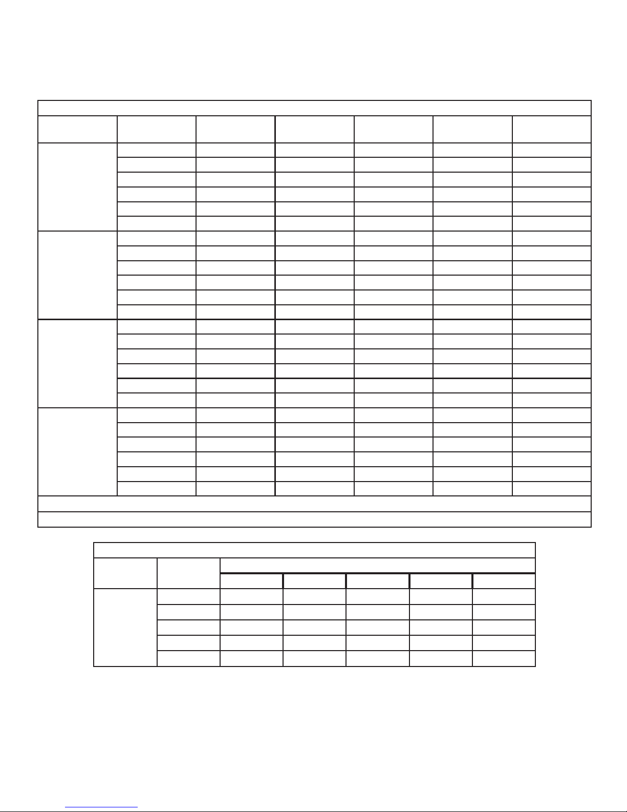
AB* / ABT* ELECTRICAL PERFORMANCE PSC MOTOR
Model
Electric Heat
kW
Motor
AMPS
Tota l
AMPS MCA MOP BTUH
AB* / ABT*
12
0 1.5 1.5 1.7 15 0
3 1.5 14.0 16.3 20 10,257
**5 1.5 21.5 24.9 30 16,411
6 1.5 26.5 30.6 30 20,512
8 1.5 32.8 37.8 40 27,304
**10 1.5 41.5 47.9 50 32,764
AB* / ABT*
18 & 24
0 1.5 1.5 1.7 15 0
3 1.5 14.0 16.3 20 10,257
**5 1.5 21.5 24.9 30 16,411
6 1.5 26.5 30.6 30 20,512
8 1.5 32.8 37.8 40 27,304
**10 1.5 41.5 47.9 50 32,764
AB* / ABT*
30
0 1.5 1.5 1.7 15 0
3 1.5 14.0 16.3 20 10,257
**5 1.5 21.5 24.9 30 16,411
6 1.5 26.5 30.6 30 20,512
8 1.5 32.8 37.8 40 27,304
**10 1.5 41.5 47.9 50 32,764
AB* / ABT*
36
0 4 4.0 19.4 15 0
3 4 16.5 28.0 20 10,257
**5 4 24.8 33.8 30 16,411
6 4 29.0 43.3 35 20,512
8 4 35.3 40.9 45 27,304
**10 4 45.7 52.5 60 32,764
De-rate BTUH heating capacity by 25% for 208 VAC
Specications may change without notice
BLOWER PERFORMANCE FOR PSC
Model Speed
Static Pressure
0.1 0.2 0.3
AB* / ABT*
12
Low 535 460 400
Medium 700 630 540
High 800 730 620
AB* / ABT*
18
Low 740 670 610
Medium 970 850 760
High 1020 950 840
AB* / ABT*
24
Low 740 670 610
Medium 970 850 760
High 1020 950 840
AB* / ABT*
30
Low 740 670 610
Medium 970 850 760
High 1020 950 840
AB* / ABT*
36
Low 1020 950 870
Medium 1140 1100 1040
High 1250 1200 1150
AH* SERIES
FURRED DOWN
AIR HANDLER
AH* / AT* ELECTRICAL PERFORMANCE ECM MOTORS
Model
Electrical Heat
kW
Motor
AMPS
Tota l
AMPS MCA MOP BTUH
AB* / ABT*
12
0 2.8 2.8 3.2 15 0
3 2.8 15.3 17.9 20 10,257
**5 2.8 22.8 26.5 30 16,411
6 2.8 27.8 32.3 35 20,512
8 2.8 34.1 39.4 45 27,304
**10 2.8 44.5 49.5 60 32,764
AB* / ABT*
18 & 24
0 2.8 2.8 3.2 15 0
3 2.8 15.3 17.6 20 10,257
**5 2.8 22.8 27.2 30 16,411
6 2.8 27.8 32.0 35 20,512
8 2.8 34.1 39.4 45 27,304
**10 2.8 44.5 51.1 60 32,764
AB* / ABT*
30
0 4 4.0 4.6 15 0
3 4 16.5 19.4 20 10,257
**5 4 24.0 28.0 30 16,411
6 4 29.0 33.8 35 20,512
8 4 35.3 40.9 50 27,304
**10 4 44.0 51.0 60 32,764
AB* / ABT*
36
0 4 4.0 0.0 15 0
3 4 16.5 19.4 20 10,257
**5 4 24.0 28.0 30 16,411
6 4 29.0 33.8 40 20,512
8 4 35.3 40.9 50 27,304
**10 4 44.0 51.0 60 32,764
De-rate BTUH heating capacity by 25% for 208 VAC
Specications may change without notice
BLOWER PERFORMANCE ECM MOTORS
Model
Speed
Tap
Static Pressure
0.1 0.2 0.3 0.4 0.5
AB* / ABT*
18 & 24
1 0
Low (2) 650 640
Medium (3) 760 720 690 650 610
Med High (4) 860 840 790 740 680
High (5) 900 890 840 800 750
AB* SERIES
FURRED DOWN
AIR HANDLER
Coil Company, L.P
AllStyle Coil Company, L.P.
STANDARD 5 YEAR
PRODUCT LIMITED WARRANTY
January 2018
AllStyle Coil Company, L.P. makes the following standard limited warranties for products manufactured for residential applications installed in the United
States and Canada. Registered evaporator coils and air handler DX coils installed in residential applications are given a standard limited 5 year warranty.
Non-registered residential evaporator coils and air handler DX coils have a limited 1 year warrany. Hydronic coils in a residential application have a
standard limited 2 year warrany. Coils installed in commercial applications are provided a standard limited 2 year warranty (Coil Only), and a limited 1
year warranty on commercial parts. For registered multi-family applications there is a standard limited 5 year warranty for aluminum coils, and a limited
1 year warranty for parts. ese limited warranties extend to the original purchaser and any subsequent transferee, as long as the product remains at the site
of the original installation.
Limited Five (5) Year Warranty
AllStyle warrants to the purchaser of this product that should it prove defective within ve years of the date of manufacture, due to improper
workmanship and/or material under proper installation. AllStyle will repair or replace, at its option, any defective part without charge for the part.
Replacements Parts/Coils are warrantied for the remainder of the original warranty period.
is limited warranty does NOT include labor or other costs incurred for the servicing, maintenance servicing, replacing, removing, shipping or
handling. You are responsible for the cost of shipping warranty replacement coils or parts from the manufacturer to the location of your covered equipment;
the cost of shipping failed parts to the distributor, and for incidental costs incurred locally, including handling charges. AllStyle will not pay for electricity,
fuel costs, increases in electricity, or fuel costs for any reason. ese costs may be covered by a separate warranty provided by the selling dealer or contractor.
In establishing the starting date for the term of this Limited 5 Year Warranty, Purchaser must register. Register on-line at www.allstyle.com/warranty
**Note: Commercial applications will include all of the above mentioned for the standard limited two (2) year warranty.
e Above Warranties are subject to the Following Conditions:
1. You must retain your bill of sale or provide other proof of purchase.
2. is limited warranty applies only while the product remains at the site of the original installation (except for mobile home
installations), and only to products installed by licensed dealers or contractors as determined by local licensing requirements.
3. is limited warranty applies only if the product is installed and operated in accordance with AllStyle instructions and in
compliance with applicable local installation, building codes, and good trade practices.
4. AllStyle requires a yearly inspection and service of the equipment by a licensed technician.
AllStyle Does Not Cover:
Any costs of installation, disconnection, or dismantling the product, or parts used in connection with normal maintenance such as lters, and
owner-required maintenance. Consult the instructions enclosed with the product for information regarding recommended maintenance. AllStyle does not
provide any reimbursement with this warranty, i.e. lodging,wages, any expenses, including freon, etc..
is Warranty Does Not Cover Damages Caused By:
(A) Accident, negligence, or abuse; (B) Operating the product in a corrosive atmosphere containing chlorine, uorine, or any other damaging
chemicals; (C) Modication, alteration, repair or service by anyone not properly qualied to perform such service modication, alteration or repair;
(D) Improper matching or application of the product or components; (E) Failure to provide proper maintenance and service to the product according to
the manufacturer’s instructions; (F) Installation or operating of the product in manner contrary to the instructions of the manufacturer; (G) Products
installed outside the United States or its territories; (H) Failure to operate due to interruption and/or inadequate electrical service; (I) Any damage caused
by frozen or broken water pipes in the event of equipment failure; (J) AllStyle is not responsible for any water damage to property. To prevent water
damage, it is the installing contractors responsibility to install proper secondary safety pans, drain lines, and oat switches to ensure proper drainage
from over-ow; (K) Damage or repair required as a result of the use of used or recycled refrigerant; (L) Lightening, oods, res, winds, corrosive
atmosphere or any other acts of God beyond the control of AllStyle. WARNING: Warranty will be voided if ANY chemical cleaning products are
used on any AllStyle coils.
How to Obtain Warranty Service:
To obtain warranty service and/or parts replacement you must notify your selling dealer or contractor of any defect within the applicable warranty period.
ALL WARRANTIES IMPLIED BY STATE LAW, INCLUDING THE IMPLIED WARRANTIES OF MERCHANTABILITY AND FITNESS FOR A
PARTICULAR PURPOSE ARE EXPRESSIVELY LIMITED TO THE DURATION OF THE LIMITED WARRANTIES SET FORTH ABOVE. Some
states do not allow limitations on how long an implied warranty lasts, so the above limitation may not apply to you. WITH THE EXCEPTION OF ANY
WARRANTIES IMPLIED BY STATE LAW AS HEREBY LIMITED, THE FOREGOING EXPRESS WARRANTY IS EXCLUSIVE AND IN LIEU
OF ALL OTHER WARRANTIES, GUARANTEES, AGREEMENT, AND SIMILAR OBLIGATIONS OF MANUFACTURER OR SELLER WITH
RESPECT TO THE REPAIR OR REPLACEMENT OF ANY PRODUCT OR PART.
IN NO EVENT SHALL ALLSTYLE BE LIABLE FOR CONSEQUENTIAL OR INCIDENTAL DAMAGES. Some states do not allow
the exclusion of incidental or consequential damages so the above limitation may not apply to you. No person, agent, distributor, dealer, or company is
authorized to change, modify, or extend terms of these warranties in any manner whatsoever. e time within which an action must be commence to enforce
any obligation of AllStyle arising under this warranty or under any statute, or law of the United States or any states thereof, is hereby limited to one year from
the date you discover or should discovered the defect. is limitation does not apply to implied warranties arising under state law so the above provision may
not apply to you. is warranty gives you specic legal rights and you may also have other rights which vary from state to state.
Any controversy or claim arising out of or relating to this warranty, or the breach thereof, shall be settled through binding arbitration administered
by the American Arbitration Association in accordance with its Commercial Arbitration Rules, and judgment on the aware rendered by the arbitrator may
be entered in any court having jurisdiction thereof. is is the exclusive and sole remedy of Buyer, for any breach of warranty. Pursuit of any legal remedy
must occur in Harris County, Houston, Texas.
is document replaces and supersedes any and all previous warranties issued by AllStyle Coil Company, L.P.
In order to maintain the remainder of the warranty period, you must replace the failed unit with an AllStyle Coil.
©AllStyle Coil Company, L.P. January 2018
Coil Company, L.P
AllStyle Coil Company, L.P.
7037 Brittmoore Road
Houston, Texas 77041
AB* SERIES INSTALLATION GUIDE 1/2018
This manual suits for next models
10
Table of contents
Other Allstyle Air Handler manuals


