manuals.online logo
Brands
  1. Home
  2. •
  3. Brands
  4. •
  5. EQK
  6. •
  7. Air Handler
  8. •
  9. EQK 18S-EHVC WD2V Series Programming manual

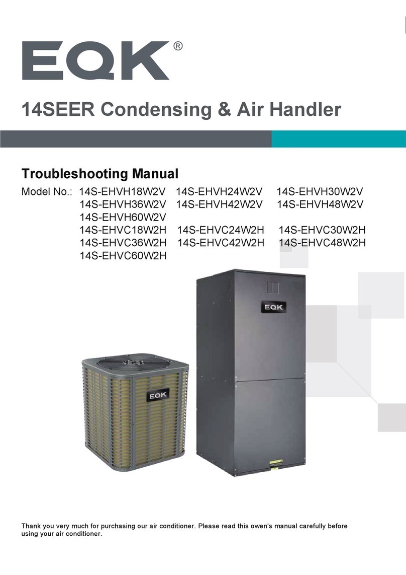
EQK 18S-EHVC WD2V Series Programming manual

Thank you very much for purchasing our air conditioner. Please read this owen's manual carefully before
using your air conditioner.
Model No.: 18S-EHVC*WD2V / 18S-EHVC*WD2H
18S-EHVH*WD2V / 18S-EHVH*WD2H
Troubleshooting Manual
18SEER Condensing & Air Handler
Troubleshooting
2
THANK YOU
Congratulations on your purchase and welcome to the Family.
Your new Air Conditioner combines high-efficiency operation with portable convenience.
By following the operating and care instructions in this manual, your air conditioner will
provide you with many years of reliable service.
Please visit our website
www.eqkhvac.com
For any questions or Technical Support,
please contact us by mail [email protected] or by phone 1-888-493-0305.
Parameter point check table
2
TROUBLESHOOTING
1. Top discharge outdoor unit
For 18S-EHV*24WD2V, 18S-EHV*36WD2V
Function description for the corresponding position:
No. Content No. Content
1 Compressor wiring terminal 12 High/Low pressure switch ports
2 DC fan motor wiring terminal 13 AC fan motor wiring terminal
3Transformer 14 Four-way valve control port
4 Outdoor display board wiring terminal 15 Crankcase Heating zone control terminal
5 Reserved 16 Chassis Electric Heater control terminal
6 24V wire controller interface 17 Solenoid valve2 control terminal
7 EXV drive port 18 Power supply connecting terminal
8 Exhaust temperature sensor port(T5) 19 Power supply connecting terminal
9 Outdoor ambient temperature sensor port(T4) 20/21 Relay
10 Condenser temperature sensor port(T3) 22 Inductor wiring terminal 1
11 Pressure sensors ports 23 Inductor wiring terminal 2
3
TROUBLESHOOTING
For 18S-EHV*48WD2V, 18S-EHV*60WD2V
Function description for the corresponding position:
No. Content No. Content
1 Compressor wiring terminal 12 AC fan motor wiring terminal
2 DC fan motor wiring terminal 13 Four-way valve control port
3Transformer 14 Crankcase Heating zone control terminal
4 Outdoor display board wiring terminal 15 Chassis Electric Heater control terminal
5 24V wire controller interface 16 Solenoid valve control terminal
6 EXV drive port 17 Power supply connecting terminal
7 Exhaust temperature sensor port(T5) 18 Power supply connecting terminal
8 Outdoor ambient temperature sensor port(T4) 19 Relay
9 Condenser temperature sensor port(T3) 20 Relay
10 Pressure sensors ports 21 Inductor wiring terminal 1
11 High/Low pressure switch ports 22 Inductor wiring terminal 2
4
TROUBLESHOOTING
For 18S-EHV*24WD2H, 18S-EHV*36WD2H 18S-EHV*48WD2H 18S-EHV*60WD2H
Function description for the corresponding position:
No. Content No. Content
1 DC fan motor wiring terminal 8 Output port of transformer(11V)
2 Reserved 9 Dip switch to adjust fan speed
3 Chassis Electric Heater control terminal 10 Power supply connecting terminal(L1)
4 Reserved 11 Fan power cord input port(L1)
5 24V wire controller interface 12 Input power cord transformer port
6 Output port of transformer(24V) 13 Power supply connecting terminal(L2)
7 Fuse 14 Fan power cord input port(L2)
2. Air handing unit
5
TROUBLESHOOTING
Error code
(1) The error codes for outdoor unit as follows:
Definitions of malfunction Error code
T4 Outdoor ambient temperature sensor error E4
T5 Discharge temperature sensor error E5
T3 Condenser temperature sensor error E6
AC under voltage protection E9
EEPROM error E10
IPM modular sensor error E12
HLP Pressure sensor error E13
T3 or T5 sensor disconnect error E14
High pressure switch error E15
Communication error of main chip and IPM chip H0
T3 sensor high temperature error(In cooling mode, 20 times P5 error within 180mins) H1
High pressure switch error(20 times P1 error within 150 mins) H2
High pressure abnormal in heating mode (20 times P13 error within 180 mins) H3
IPM modular high temp error (20 times P8 within 120 mins) H4
Low pressure error (20 times P2 within 100 mins) H5
Discharge temperature abnormal error(20 times P4 within 100 mins) H6
Wet operation error (20 times P12 within 200 mins) H7
T3 condenser sensor disconnect error (20 times E14 within 100 mins) H8
Discharge temp sensor disconnect error(20 times E14 within 180 mins) H12
High pressure protection P1
Low pressure protection P2
DC over current protection P3
T5 Discharge temperature abnormal error P4
T3 Condenser sensor high temp protection(In cooling mode) P5
IPM module protection P6
IPM high temperature protection (Ft)M high temperature protection (Ft) P8
DC fan motor error P9
Wet operation error P12
High pressure abnormal error(In heating mode) P13
6
TROUBLESHOOTING
High compression ratio protection P14
Low compression ratio protection P15
DC cable bus low voltage protection L1
DC cable bus high voltage protection L2
MCE fault / sync / closed loop L4
Zero speed protection L5
Compressor phase loss protection ratio protection L7
Compressor stalls L8
Frequency limitation or decline by high pressure L9
Frequency limitation by voltage LA
Frequency limitation by condenser temp. LC
Frequency limitation by discharge temp LD
Frequency limitation by IPM modular high temp LE
Frequency limitation by current LF
Oil return d0
Defrost dF
Force cooling dH
7
TROUBLESHOOTING
(2) Troubleshooting by error code
E4/E5/E6 (T4/T5/T3 temperature sensors error)
Diagnosis Handling
T5/TP T4 T3
E10 (EEPROM failure)
Diagnosis Handling
Check the connection
between the sensor and PCB
The sensor should be
connected firmly and correctly
Error
Check if the sensor is damaged
OK
Replace with a new sensor, and insert
it in the corresponding position
Yes
Replace the main board
No
Power off and re-power on to
see whether it is normal
If there is still abnormal
replace the mainboard
8
TROUBLESHOOTING
E9 ( AC under voltage protection )
Diagnosis Handling
E12 (IPM modular sensor error)
Diagnosis Handling
The power supply wire should
be connected firmly and correctly
Check if the power supply
wire is reliably connected
Check if the wire diameter meets
the requirements in the manual
Yes
Replace the power cord
to the right diameter
Check if the compressor
wiring is correct
Yes
The power supply
wire interface
It should be connect correctly
according to the wiring diagram
Yes
If there is still abnormal
replace the mainboard
No
Power off and re-power on to
see whether it is normal
The compressor
wire interface
No
No
No
Power off and re-power on to
see whether it is normal
If there is still abnormal
replace the mainboard
9
TROUBLESHOOTING
E13 (HLP Pressure sensor error)
Diagnosis Handling
E14/H8/H12 (T3 or T5 sensor disconnect error )
Diagnosis Handling
Check the connection
between the sensor and PCB
The sensor should be
connected firmly and correctly
Error
Measure the value of outdoor
unit pressure sensor
Compare it with the pressure
value of the pressure gauge
OK
If the difference is large,
replace with a new sensor, and
weld in the correct position
If the difference is small,
replace the mainboard
The pressure sensor should be
soldered in the correct position
Check the connection
between the sensor and PCB
The sensor should be
connected firmly and correctly
Error
OK
Replace the sensor
10
TROUBLESHOOTING
E15 ( High pressure switch error )
Diagnosis Handling
H0 (Communication error of main chip and IPM chip )
Diagnosis Handling
Check the connection
between the switch and PCB
The switch should be
connected firmly and correctly
Error
Try to short circuit
the pressure switch
OK
If there is still abnormal,
replace the mainboard
If the error disappears, check
if the switch is damaged
If it is damaged, replace with a new one,
and solder it in the correct position
The high pressure switch should be
soldered in the correct position
Power off and re-power on to
see whether it is normal
If there is still abnormal replace
the mainboard
11
TROUBLESHOOTING
P1/H2 ( High pressure switch protection )
Diagnosis Handling
P2/H5 (Low pressure switch protection)
Diagnosis Handing
Use the pressure gauge to
detect the system pressure to
see if the change is normal
The pressure switch has damaged,
and replace it with a new one
Check if the liquid pipe in
the system is blocked Remove dirty and keep it unobstructed
Check if there’s too much
refrigerant in the system
Discharge some refrigerant
from the system
No
Discharge the refrigerant,
vacuum, recharge refrigerant
Check if there is too much
Air or N2 in the system
No
No
Yes
Yes
Yes
Yes
Check if the gas pipe in
the system is blocked
No
Remove dirty and keep it unobstructed
Check if the refrigerant of
the system is insufficient
Charge some refrigerant into
the system
Yes
Replace the mainboard
Use the pressure gauge to
detect the system pressure to
see if the change is normal
The pressure switch has damaged,
and replace it with a new one
No
No
Yes
Yes
12
TROUBLESHOOTING
P5/H1( T3 condenser sensor high temp protection )
Diagnosis Handling
P6 (IPM module protection)
Diagnosis Handling
P8/H4 (IPM high temperature protection)
Diagnosis Handling
Check if the liquid side of
outdoor system is blocked
Remove dirty and keep it unobstructed
Check if there is too much
Air or N2 in the system
Discharge the refrigerant,
vacuum, recharge refrigerant
No
No
Power off and re-power on
to see whether it is normal
Yes
Yes
If there is still abnormal
replace the mainboard
Power off and re-power on to
see whether it is normal
If there is still abnormal
replace the mainboard
Re-power on to measure the
temperature of the IPM board
Observe the temperature change
If the temperature changes normally, but the final
temperature is too high, remove the IPM heat sink cover
plate, apply heat dissipation silicone grease evenly
again, then tighten the screws to fasten the cover plate
No
Replace the mainboard
IPM heat sink cover plate
should be fastened
13
TROUBLESHOOTING
P9 ( DC fan motor error )
Diagnosis Handling
P5/H1( T3 condenser sensor high temp protection )
Diagnosis Handling
Check if the DC fan
motor wiring is correct
It should be connect correctly
according to the wiring diagram
No
Power off and re-power on
to see whether it is normal
Replace the mainboard
Check if the DC fan
motor is damaged
If it is damaged, replace with a new one
Yes
Yes
No
The DC fan motor
wire interface
Power off and re-power on to
see whether it is normal
14
TROUBLESHOOTING
P13/H3(High pressure abnormal error(In heating mode) )
Diagnosis Handling
P14 (High compression ratio protection)
Diagnosis Handling
P15 (Low compression ratio protection)
Diagnosis Handling
Check if the liquid side of
outdoor system is blocked
Remove dirty and keep it unobstructed
Check if there is too much
Air or N2 in the system
No
Discharge the refrigerant,
vacuum, recharge refrigerant
Yes
Power off and re-power on
to see whether it is normal
If there is still abnormal
replace the mainboard
No
Yes
Yes
Check if the refrigerant is lack
or the refrigerant is
No
Charge some refrigerant into the system
Yes
Check if there is too much
Air or N2 in the system
Discharge the refrigerant,
vacuum, recharge refrigerant
Power off and re-power on to
see whether it is normal
Check if the throttle part of
the system is blocked
Remove dirty and keep it unobstructed
If there is still abnormal
replace the mainboard
No
No
Yes
Yes
Yes
Yes
Power off and re-power on
to see whether it is normal
No
If there is still abnormal
replace the mainboard
Check if the throttle part of
the system is blocked
Remove dirty and keep it unobstructed
15
TROUBLESHOOTING
L1/L2( DC cable bus low/high voltage protection )
Diagnosis Handling
L4-L8 (IPM module subdivision protection)
Diagnosis Handling
L9-LE (Frequency limitation protection, not error)
Check if the voltage is normal Replace the mainboard
Yes
The power supply is
too low or too high
No
Connect a transformer before connecting
the unit to the power supply, then adjust the
voltage to the normal operation range
Power off and re-power on to
see whether it is normal
If there is still abnormal
replace the mainboard
Emerson Quiet Kool Co. Ltd.
120 US-46 Parsippany-Troy
Hills, NJ 07054
Toll Free 1-888-493-0305
Version Update:--2021.5.0

This manual suits for next models

3

Other EQK Air Handler manuals

EQK 14S-EHVC18W2V User manual

EQK

EQK 14S-EHVC18W2V User manual

EQK 14S-EHVH18W2V Programming manual

EQK

EQK 14S-EHVH18W2V Programming manual

EQK EAC2H18R2C User manual

EQK

EQK EAC2H18R2C User manual

EQK EACH7R2W User manual

EQK

EQK EACH7R2W User manual

Popular Air Handler manuals by other brands
Boneco H700 manual

Boneco

Boneco H700 manual

ForestAir E-Tech Series installation manual

ForestAir

ForestAir E-Tech Series installation manual

CIAT FLOWAY CLASSIC RHE manual

CIAT

CIAT FLOWAY CLASSIC RHE manual

inVENTer aV100 ALD Instructions for use

inVENTer

inVENTer aV100 ALD Instructions for use

Vents VUT 2000 PBE EC user manual

Vents

Vents VUT 2000 PBE EC user manual

Lennox CBA25UH Series installation instructions

Lennox

Lennox CBA25UH Series installation instructions

Rec Temovex G10125 user manual

Rec Temovex

Rec Temovex G10125 user manual

BLAUBERG BlauAir CFV Series user manual

BLAUBERG

BLAUBERG BlauAir CFV Series user manual

Goodman ASPF Series Installation & operating instructions

Goodman

Goodman ASPF Series Installation & operating instructions

BLAUBERG Komfort EC S5B270 S14 installation guide

BLAUBERG

BLAUBERG Komfort EC S5B270 S14 installation guide

RenewAire EV Series Installation, operation and maintenance manual

RenewAire

RenewAire EV Series Installation, operation and maintenance manual
innovair MULTI-MAX Series Service manual

innovair

innovair MULTI-MAX Series Service manual

BLAUBERG KOMFORT EC D5B 180 user manual

BLAUBERG

BLAUBERG KOMFORT EC D5B 180 user manual

Dettson AHB080014 installation instructions

Dettson

Dettson AHB080014 installation instructions

Daikin Modular Rotary Instructions for installation, use and maintenance manual

Daikin

Daikin Modular Rotary Instructions for installation, use and maintenance manual

Ingersoll-Rand TAM9A0A24V21DA Installer's guide

Ingersoll-Rand

Ingersoll-Rand TAM9A0A24V21DA Installer's guide

Goodman ARUF**14 Series Installation & operating instructions
Goodman

Goodman ARUF**14 Series Installation & operating instructions
VTS Medical Systems VOLCANO VR Mini Technical documentation

VTS Medical Systems

VTS Medical Systems VOLCANO VR Mini Technical documentation

manuals.online logo
manuals.online logoBrands
  • About & Mission
  • Contact us
  • Privacy Policy
  • Terms and Conditions

Copyright 2025 Manuals.Online. All Rights Reserved.