Alltrack USA Plug-In Service manual

‘Plug-in’
Real Time GPS
Installation Instructions

This page intentionally left blank.

1
TABLE OF CONTENTS
1. Introduction………………………………………………………………………2
2. Precautions before installing the Device……………………………………. 5
3. Installing the Device…………………………………………………………… 5
4. Powering the Device & Confirming Proper Operation……………………… 6
5. Testing…………………………………………………………………..………. 7

2
1. Introduction
This installation manual covers the installation of the Alltrack USA ‘Plug-in Real Time
with History’ GPS Tracking Unit. It can be used on 12 volt DC vehicles that have an
OBD II port (all 1996 and newer vehicles have this port).
GPS and Cellular antennas are built into the device.
This device is connected directly to the vehicle’s 12-volt DC system via the OBD II port.
It operates 24 hours a day and must be kept energized to log vehicle events and send
travel data.
OBD II Port
All vehicles made since 1996 have this port, which looks like this from the front:
The port is probably black but may be a different color.
Here’s a side view of an OBD II port:

3
•The OBD II port may or may not be easily visible from view, but it’s there.
•It may located be behind a plastic cover.
•Or it may be behind the lower edge of the dash where it can be felt by hand or
with a mirror.
If device protrudes too much from dashboard into knee area
Once in awhile, a vehicle’s OBD II port may be in a location where plugging in the
device will cause it to protrude too much into the knee area. You certainly don’t want it
to be in the way of your knees while driving.
To overcome this, a small cable can be used to relocate the device to a better area
below the dashboard. One end plugs into the device and the other end plugs into the
vehicle’s OBD II port and is very flat and stubby.

4
We offer these cables for $7.49 + shipping. They’re also available at amazon.com –
search there for this: “Flat Low Profile Male to Female OBD II 2 Extension Cable”.
Backup Battery
The device has a built-in backup battery, which is 200 mAh, 3.7 Volt rechargeable
Lithium-ion.
The primary function of the backup battery is to provide enough power to allow
notification to a user when there is a loss of power to the device. Power loss can
indicate device tampering or battery disconnection or removal.

5
2. Precautions before installing the device
As you prepare to install the device, be sure to heed the following precautions and
guidelines:
•The device is NOT waterproof or sealed. Keep it away from water and any other
liquids. It should NEVER be mounted in the engine compartment nor outside of the
vehicle.
•Prior to installing the device, the vehicle’s ignition is turned Off.
•It’s recommended that you install in the vehicle’s built-in OBD II port. If you use
some kind of wiring to relocate where the device plugs into another auxiliary OBD II
port, take these precautions:
- DO NOT place objects, including communication equipment like this, in the area
over the airbag or in the air bag deployment area. If the communications equipment
is improperly installed and the airbag inflates, this could cause serious injury.
- DO NOT run cables under the area reserved for the driver’s feet.
3. Installing the Device
•Have the vehicle’s ignition turned Off.
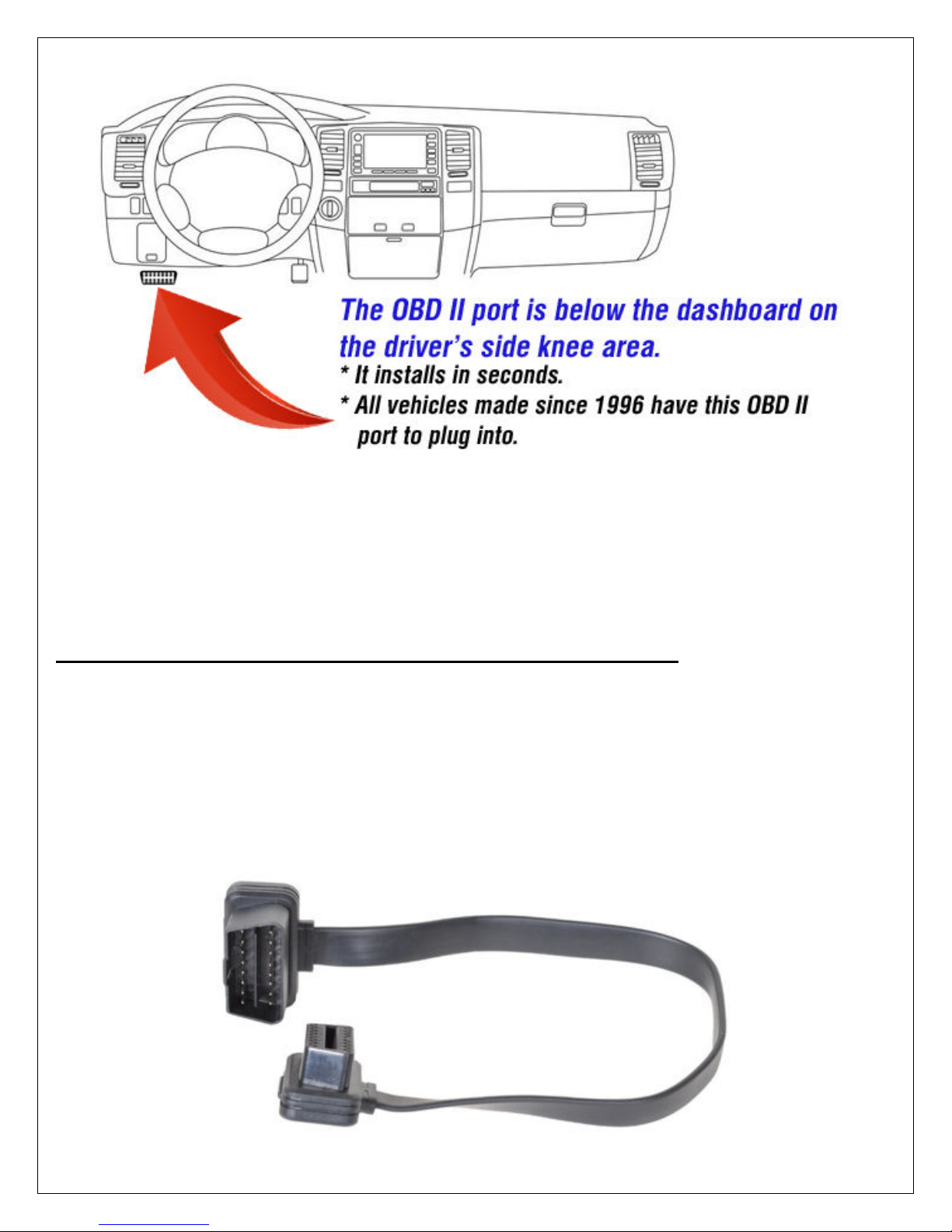
•Locate the OBDII socket in the vehicle. All vehicles made since 1996 have this port
installed. It should be below the driver’s side dashboard in the knee area. It’s
probably black but may be a different color.
- The location will vary between different vehicle manufacturers, models, and
production years.
- If it isn’t visible, it may be either behind a plastic cover or be behind the base of
the dashboard.
- If you can’t find it, look in the vehicle’s owner’s manual for its location.
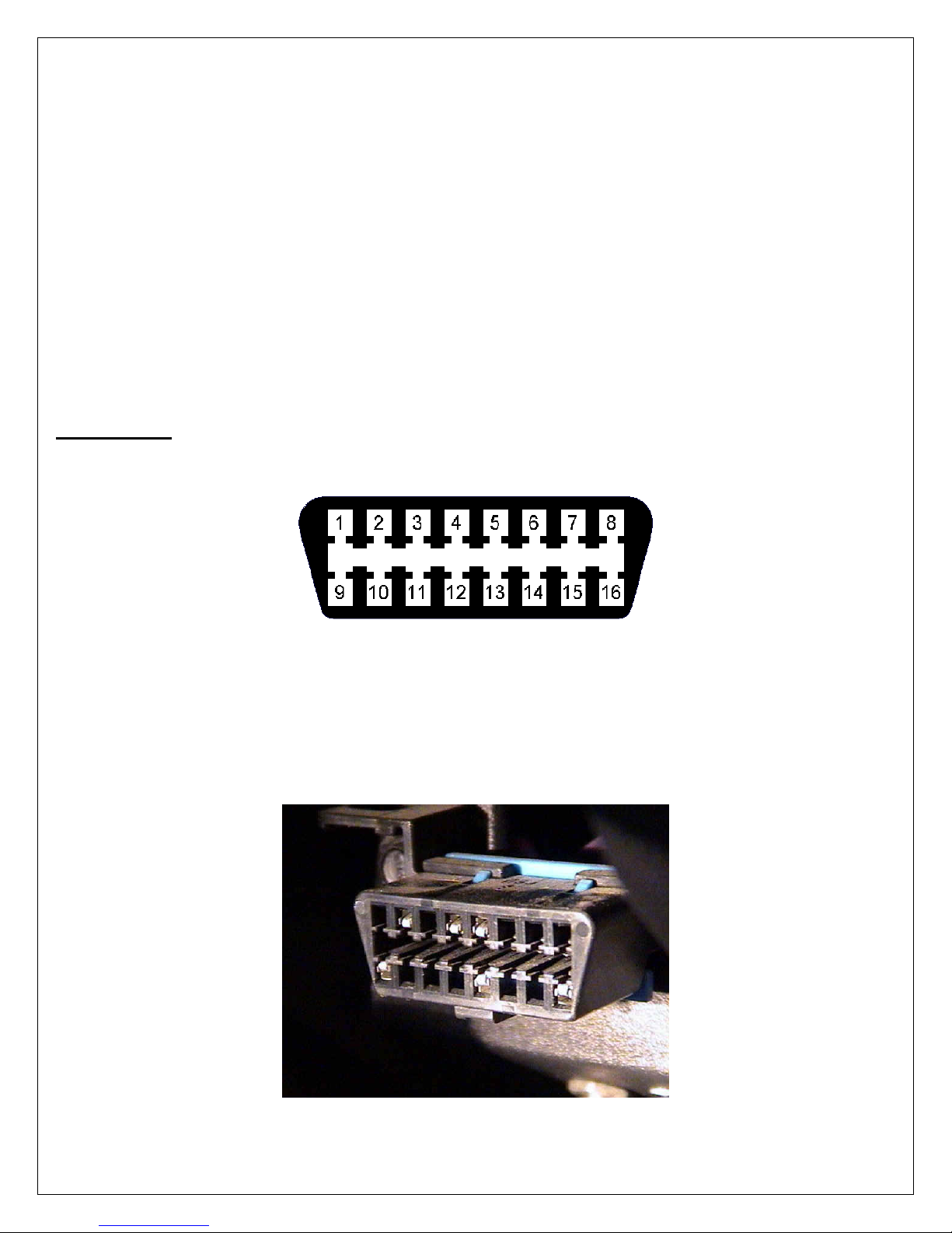
•Note the orientation of the vehicle’s port and of the device. It plugs in just 1 way.
This is what the port looks like on the vehicle:
•Carefully insert the device into the OBDII socket. It’ll plug in about ½” until it won’t
push in any more.
•The vehicle needs to be started and run for several minutes in order for the
device to initially power up and get acclimated. The next time you drive the
vehicle, it’ll get acclimated. But if you’re in a hurry to do this, start the engine and let
it idle for about 4 minutes.

6
4. Powering the Device & Confirming Proper Operation
The device includes LEDs to indicate Cellular connectivity, GPS and Power. The
following image shows the location of each LED on the side of the device. In the
picture below, the 3 LEDs are in the lower left corner.
Approximately 3 hours after the ignition is turned Off, the device goes into a Low-
Power Sleep mode. The device will awaken when the vehicle is started.
The LEDs are described in this table:
Orange = Cell
•
The LED flashes at a slow rate when it’s searching for cellular
connectivity.
•It flashes fast when the cell network is available.
•It stays on solid when connected to the cell network.
Green = GPS
•
The GPS LED flashes at a fast rate when the unit is acquiring a
satellite fix.
•It blinks at a slow rate when “time-syncing” with the satellites.
•Once a fix is acquired, the LED stays on solid.
Red = Engine
running
•
The LED is On solid when the vehicle’s Ignition is On AND the
engine is running.
•It’s off when the vehicle’s Ignition is turned Off.
If the device is plugged in, the vehicle’s engine is running, but the
Red LED is Off, check if the vehicle’s OBD port is getting power --
at pin #16 in the lower right corner on your vehicle.

7
5. Testing
The vehicle needs to be started and run for several minutes in order for the
device to initially power up and get acclimated. Then this testing can be done.
The next time you drive the vehicle, it’ll get acclimated
But if you’re in a hurry to get the device acclimated, start the engine and let it idle for
about 4 minutes.
The Red power LED and the Orange cellular connectivity LED will illuminate to indicate
the device is working.
Then, congratulations, you have just installed the Internet based vehicle GPS
telematics system. Now on to testing:
•Start the vehicle and let it idle for at least 1 minute. Then turn it off.
•Go to a computer and access the Internet using your standard Internet browser.
•Go to the web page track.alltrackusa.com
•Enter customer login and password. Then click login.
•You will now see the tracking map. The vehicle should be where the map shows it
to be.

8
•On the left is a row listing the vehicle. The column ‘Last’ shows when the vehicle
last called in, which should have been when you just turned On and Off the Ignition.
So this should say something like ‘1m’ for 1 minute or so. Or ‘0m’ for 0 minutes.
If it says a high amount like 60 minutes, check that the device is pushed in all the
way and that the LEDs on the device are coming on.
___________________________________________________
To test the Backup Battery:
•Temporarily pull the device out of the OBD II port.
•After a minute or so, in the upper right corner, a popup should appear saying that
the Primary Power has been lost and device is operating on backup battery power
now.
•Plug the device back into the OBD II port.
•After a minute or so, in the upper right corner, a popup should appear saying that
the Primary Power has been Re-applied.
•At the popup, click ‘Accept’.
That’s it for testing !!
Table of contents