Altec AIR UA Series User manual

Owners Manual
UA & MHT Series
Refrigerated Air Dryer
IMPORTANT: READ THIS MANUAL CAREFULLY. IT
CONTAINS INFORMATION ABOUT SAFETY AND THE
SAFETY OF OTHERS. ALSO BECOME FAMILAR WITH
THE PROPER INSTALLATION AND CONTROLS OF THE
AIR DRYER BEFORE OPERATING. ONLY QUALIFIED,
TRAINED AND LISCENSED PERSONAL SHOULD
SERVICE OR OPERATE THIS EQUIPMENT. RECORD
THE INFORMATION BELOW AND SAVE THIS MANUAL.
IF SERVICE IS NEEDED THE INFORMATION BELOW
WILL BE NEEDED.
CAUTION:THIS MACHINE CONTAINS HIGH PRESSURE
GAS AND ELECTRICITY.
NOTE: Please record the information below and keep this manual. If you need service on this dryer
you will need this information.
Model #_____________________________
Serial #______________________________
Voltage______________________________
Purchased from:______________________________________________________________
DESCRIPTION PAGE
INTRODUCTION
RECEIVING & INSPECTION
2
INSTALLATION 3
INSTALLATION GUIDE 4
DRYER CONTROLS & SAFTEY
SHUTDOWNS
START UP
5-6
INITIAL RUN PROCEDURE 7
MAINTENANCE PROCEDURES
HOW THE AIR DRYER WORKS
8
DESCRIPTION OF
COMPONENTS
9
TROUBLE SHOOTING GUIDE 10
ELECTRICAL SCHEMATICS 17-20
SERVICE LOG 21
CONTACT INFO 22
TECHNICAL SPECIFICATION 11-14
DATA LABEL—UA SERIES 15
DATA LABEL—MHT SERIES 16

2
INTRODUCTION
Thank you for selecting an UA/MHT Series refrigerated air dryer from Altec AIR.
The refrigerated air dryer is specifically designed and manufactured for drying and purifying compressed air
generated by an air compressor.
Please read this instruction manual carefully before using the air dryer and pay attention to the precautions in
transportation, installation and operation that are listed in this manual.
Please use the dryer according to our application guide and be sure to perform the proper preventative
maintenance as recommended in this manual. Failure to perform the preventative maintenance will void the air
dryer warranty.
Refrigeration used in this air dryer is environmentally friendly R134a or R404a and is available at local
refrigeration wholesalers.
Direct any questions not covered in this manual to your distributor or call Altec AIR @ 1-800-521-5351. Before
calling with questions always have the air dryer model #, serial # and pressure gauge readings.
Service and maintenance can be obtained from your distributor. If you do not know your distributor please
contact the factory. Authorization must be obtained from Altec AIR before any parts or dryers are returned to
the factory. Altec AIR will not be responsible for anything returned without authorization.
RECEIVING AND INSPECTION
The dryer cannot be tilted on its side or upside down during shipping.
Use forklift from the bottom of the dryer when installing or moving.
Dryers are shipped F.O.B. factory. Immediately upon arrival check the dryer for possible damage. If damage is
found, report it to the carrier and file a damage claim. Check dryer data label to be sure you have the right
dryer. Check the data labels voltage and amperage to be sure it is correct and the one you ordered. Check the
refrigeration gauges for pressure.
If the gauges read 0 PSIG, STOP.
Do not start the dryer. Contact Altec AIR or your local distributor for service. This could mean there is a leak in the
refrigeration system.
Data Label
The data label is affixed to the outside of the cabinet.
This label identifies the air dryer’s model and serial
numbers and important technical data.
Before installing the dryer check all of the
information on the data label for the correct model
and voltage.
If the model number and voltage are incorrect do
not install or power ON the dryer.
Contact Altec AIR or your local distributor
immediately.

3
INSTALLATION
DRYER LOCATION / VENTILATION
Install dryer only in a well-ventilated, clean, dry area and keep at least 3 feet between the dryer, other
equipment and the walls. Dust and dirt particles will clog the air-cooled condenser and will reduce the
performance of the dryer and will eventually cause damage to it.
Do not install the dryer outside. The air dryer must not be exposed to direct sunlight, rain or snow.
AMBIENT TEMPERATURES
Suitable ambient temperature for the refrigerant dryer is a MIN of 45°F to a Max of 110°F. The performance of
the dryer will be significantly decreased when the air dryer is subject to temperatures higher than 110°F.
For installations with ambient temperatures higher than 110°F it is recommended to use a water-cooled
condenser on the dryer. Contact Altec AIR or your local distributor for details
INLET & OUTLET CONNECTIONS
Do not mix the air inlet and outlet air flow. Pipe diameter should be sized according to air flow requirements. It
is recommended that a vibration absorber be installed on the dryer inlet and outlet to eliminate vibration from
the compressor. Do not use the inlet and outlet of the air dryer to support the weight of the air piping.
FILTRATION, BYPASS VALVES, & CONDENSATE DRAINS
Appropriate pre and post filtration should be installed to protect the air dryer as well as the compressed air
system.
Isolation or 3-valve bypass should be installed on the air dryer outlet and inlet ports to allow for bypassing,
depressurizing, proper maintenance, and servicing of the air dryer.
Condensate drains must be properly piped from the dryer to prevent moisture re-entrainment. The dryer is
equipped with an automatic drain valve that controls the discharge of the condensate. The user must run a
drain line to an environmentally approved condensate collection/disposal system.
ELECTRICAL INSTALLATION
The dryer Data Label lists the electrical power requirements for the air dryer. The user must confirm that the line
voltage matches the voltage listed on the data label. (Warning – Operating the air dryer with improper line
voltage will void the warranty). Provide the proper size wire, disconnect switches and fuses in accordance with
applicable codes. Field wiring must comply with local and national fire safety and electrical codes. Standard
dryer’s enclosures and controls are designed to meet NEMA 1 Type 1 electrical standards.
Connect power leads as indicated in the electrical schematic. Ground the frame properly.
IMPORTANT NOTE: UA/MHT series dryer refrigeration compressors must be wired for proper rotation with the
proper phases L1, L2, L3. To check if dryer is wired properly turn dryer on and observe the REFRIGERANT
SUCTION PRESSURE GAUGE, immediately after the dryer is switched ON the pressure on this gauge should drop.
If after 30-45 seconds the pressure does not drop switch the dryer OFF. This could mean the dryer is wired
wrong. Switch any 2 leads and repeat.
MAXIMUM WORKING PRESSURE - 232 psig.
BREATHING AIR APPLICATIONS
This dryer has not been tested for breathing air applications. The owner is advised to do its own testing and use
for breathing air applications at owns risk.

4
INSTALLATION GUIDE
(1) Air Compressor
(2) ADF Series Drain Valve
(3) Air Receiver Tank
(4) AC Series X5 Pre-filter
(5) AC Series X1 Pre-filter
(6) AC Series XA After filter
(7) 3 Valve Bypass
(8) UA/MHT Series non-cycling air dryer
(9) AW Series Water Separator
(10) Centrifugal separator
INSTALLATION A: Recommended for systems that consume less than or equal to the maximum capacity
of the air compressor.
INSTALLATION B: Recommended for systems that consume more than the maximum capacity of the air
compressor.

5
DRYER CONTROLS
1. ON/OFF Switch – Turns the refrigerant compressor and dryer ON.
2. Dryer ON Light – Indicates the air dryer is turned on and operating. Integrated into ON/OFF Switch
3. Refrigerant Suction Pressure Gauge - Displays refrigeration system low side (Evaporator) pressure.
(Installed on UA75/MHT40 and above)
4. Refrigerant Discharge Pressure Gauge - Displays refrigeration system high side pressure. (Installed on
UA400/MHT200 and above)
5. Inlet Compressed Air Temperature Gauge - Displays air temperature for the compressed air source
(Installed on UA1600 and above)
6. Dewpoint Temperature Gauge - Displays outlet dewpoint to ensure dryer is performing correctly.
(Installed on UA20 to UA55, and MHT25)
7. Hot Gas Bypass Valve (HGBV) – Prevents compressed air freeze ups by controlling the evaporator
pressure.
8. Temperature Expansion Valve (TXV) - Metering device between the liquid refrigerant line to the
evaporator. (Installed on UA400/MHT200 and above)
9. High Pressure Shutdown w/manual reset - Shuts down dryer in the event of overload conditions
(Installed on UA150/MHT100 and above)
10. Low Pressure Shutdown - Shuts down the dryer in the event of low ambient temps or if there is a
refrigerant leak in the system. (Installed on UA200A-3/MHT130A-3 & UA250-2/MHT150A-2 and
above)
11. Fan Cycling Switch(s) - Cycles condenser fan(s) ON and OFF during periods of low ambient
temperatures. (Installed on UA400 and above).
12. Programmable Electronic Auto-Drain Valve – Automatically controls the draining of liquid condensate
removed by the dryer.
13. Compressor Internal Overload. - Shuts down the refrigerant compressor if amp draw/heat is to high.
14. Control Fuses - Shuts down the dryer in the event of high amp draw on the control circuit.
Dryer Model Refrigerant Normal
SUCTION PSIG
Dew point Temp
UA20 to UA150 R134A 25 to 35 PSIG 33 to 39 F
Normal
DISCHARGE PSIG
75-120 PSIG
UA200 to UA2000 R404A 69 to 85 PSIG 135 to 275 PSIG 33 to 39 F
MHT25 to MHT100 R134A 25 to 35 PSIG 75-120 PSIG 33 to 39 F
MHT130 to MHT200 R404A 69 to 85 PSIG 135 to 275 PSIG 33 to 39 F
ON-OFF SWITCH
W/DRYER ON LIGHT
DANGER
Only qualified and licensed refrigeration service persons should attempt to work on the air dryer.

6
DRYER CONTROLS AND SAFTEY SHUTDOWNS
HOW TO MAKE MINOR REFRIGERANT SUCTION PRESSURE ADJUSTMENTS.
Keep dryer running under a no load by turning OFF or bypassing the compressed air.
Remove dryer top and locate the Hot Gas Bypass Valve. Remove cap on Hot Gas By-
pass Valve and turn valve counter clockwise to decrease the suction pressure and
clockwise to increase the suction pressure.
Make ½ turn adjustments and wait 2 to 3 minutes for suction pressure to stabilize.
Make more adjustments if needed.
HIGH PRESSURE SHUTDOWNS WITH MANUAL RESET
Shuts the dryer down in the event of a dirty condenser, fan motor failure or
excessively high ambient temperatures (Installed on UA150/MHT100 and
above)
LOW PRESSURE SHUTDOWN
Shuts the dryer down in the event of low ambient conditions or if there is a
leak in the refrigeration system. (Installed on UA400/MHT200 and above)
START UP
The following procedure must be followed to start your air dryer. Failure to follow this start up proce-
dure will void your warranty. If problems occur during start up, contact Altec AIR or your local distribu-
tor.
1. Turn the ON/OFF switch to the OFF position.
2. Verify the main electrical supply voltage matches the voltage specified on the data label.
3. Check the proper connection and support of the compressed air lines to the dryer: check dryer by-
pass and isolation valve system.
4. Confirm that the inlet and ambient air temperature, pressure and flow to the dryer meet the speci-
fied requirements.
5. Confirm that the condensate drain lines from the separator are properly piped to an environmentally
approved disposal system

7
INITIAL RUN PROCEDURE
After start up and checks are complete and after the main electrical power to the dryer has been
connected, follow the procedure below to put the dryer in operation:
1. Turn ON the dryer ON/OFF switch.
2. Let the dryer run for 15 minutes.
IMPORTANT NOTE: All 230/460/575 VAC, 3 Phase motors MUST be wired for proper rotation.
After the air dryer is turned ON, the suction pressure should DECREASE (pull down) instantly. If
the suction pressure does not pull down TURN OFF THE AIR DRYER IMMEDIATELY and contact
your local distributor or Altec AIR for assistance
3. Check the Refrigerant Suction Pressure (on Gauge UA75/MHT40 and above):
R134a dryers. (28 psig to 34 psig)
R404a dryers. (72 psig to 80 psig)
4. Check the Refrigerant Discharge Pressure (on Gauge UA400/MHT200 and above):
R134a dryers. (90 psig to 150 psig)
R404a dryers. (220 psig to 350 psig)
5. Verify that the condenser fan motors are operating. On units UA400/MHT200 and above fan will cycle
ON and OFF as follows:
FAN 1 R404a dryers. (ON at 230 PSIG, OFF at 135 PSIG)
FAN 2 R404a dryers. (ON at 275 PSIG, OFF at 195 PSIG)
5. Allow compressed air to flow through the dryer.
6. Confirm that condensate is discharging from the condensate drain. This may take 30-60 minutes.
7. Make sure bypass valves are closed and 100% of the air from the compressor is flowing
through the dryer.
HOW TO SET THE CONDENSATE DRAIN OPEN &
CLOSED TIME (LOCATE DRAIN VALVE)
The OPEN (ON) time is adjustable from 0.5 sec to 10 sec. Drains are
set at factory to open for 6 sec. When drain opens the on light will light
The CLOSED (OFF) time is adjustable 0.5 min to 45 min. Drains are set
at factory to stay closed for 10 min. When drain is closed the off light
will light.
You may increase or decrease this based on moisture levels in the air.
Push the TEST button to manually open the drain valve.
TO CLEAN VALVE
1. Close isolation valve
2. Push the push to test button to release the
pressure
3. Remove strainer/filter and screen.
4. Clean screen and replace.

8
MAINTENANCE PROCEDURES
Daily Maintenance
Check the operation of the automatic drain valves at least once during each eight hour shift.
Check Dew point Indicator to make sure it is the proper range. (UA10 to UA55 & MHT25)
Check Suction Pressure Gauge to make sure it is the proper range. (UA75/MHT40 and larger)
Check Discharge Pressure Gauge to make sure it is the proper range. (UA400/MHT200 and larger)
Make sure condenser coil is clean and unobstructed.
Weekly Maintenance
Clean Air Cooled Condenser Coils - Blow off all dust and dirt that is on the condenser with a
compressed air maintenance gun. While cleaning the condenser fins do not damage fins.
WARNING
DRYER FAILURE DUE TO A DIRTY CONDENSER IS NOT COVERED UNDER WARRANTY
HOW THE AIR DRYER WORKS - UA/MHT SERIES
UA Series refrigerated compressed air dryers use refrigeration cooling to condense entrained moisture
out of the compressed air stream.
Warm saturated air enters the air-to-air heat exchanger at the dryer inlet. In the air –to- air heat
exchanger the inlet air is pre-cooled by the outgoing cold air. The pre-cooled air then enters the air to
refrigerant heat exchanger where it is cooled to its lowest point in the evaporator.
As the air is cooled moisture in the air changes from a vapor to a liquid. The liquid condensate is
removed from the airstream by the separator and discharged from the dryer by the automatic drain
valve. The cold air is reheated by incoming warm air as it passes back through the air-to-air heat
exchanger.
Pre-cooling the inlet air reduces the heat load on the refrigerant compressor, permitting the use of a
smaller refrigerant compressor. The out going cold air is re-heated by the incoming hot air. As a result
the outlet air is warmed up as it leaves the dryer. This prevents the outlet pipe from sweating. The air
exits the dryer and is now clean and dry, ready for use.

9
DESCRIPTION OF COMPONENTS - UA/MHT SERIES
(1) HEAT EXCHANGER MODULE - The compact aluminum module contains the air to air heat exchanger, the
air to refrigerant heat exchanger and the stainless steel mesh condensate separator.
(2) REFRIGERANT COMPRESSOR – The main function of the compressor is to circulate the refrigerant.
The compressor pumps refrigerant to the other components in the system so they can perform heat
transfer functions. The compressor also separates the high pressure from the low pressure side of the
refrigeration system.
(3) AIR-COOLED CONDENSER – One of the main functions of the condenser is to condense the high
pressure and high temp refrigerant vapor to liquid. A heavy duty fan moves ambient air across the
condenser coils removing heat from the refrigerant vapor. As the heat is removed the refrigerant
vapor the temperature change causes the refrigerant to change state from a vapor to a liquid. The
condenser is made from aluminum fins attached to copper tubes.
(4) FLTER-DRIER – Adsorbs and filters out any moisture or debris that maybe in the refrigeration
system. Moisture can cause freeze ups and dirt particles can plug capillary tubes causing system
malfunctions.
(5) TEMPERATURE EXPANSION VALVE (TXV) – The metering device meters liquid refrigerant from the
liquid line to the evaporator. Separates the high pressure side from the low pressure side in the
refrigeration system. Installed on UA400/MHT200 and above. Capillary Tube Unit installed on UA300/
MHT150 and below.
(6) HOT GAS BYPASS VALVE (HGBV)– The HGBV responds to changes in suction pressure. As the
compressed air flow (Or heat load) on the dryer changes the suction pressure will change. An
increase in air flow causes an increase in suction pressure a decrease in air flow causes a decrease in
suction pressure. During periods of low air flow the HGBV meters hot gas from the hot gas line of the
high side to the inlet of the heat exchanger.
(7) LP1 - LOW PRESSURE SAFETY CUT OUT – Prevents damage to the refrigerant compressor in the
event of a refrigerant leak or low refrigerant pressure. Installed on UA200A-3/MHT130A-3 & UA250-
2/MHT150A-2 and above
(8) PS1—HIGH PRESSURE SAFETY SHUTDOWN w/MANUAL RESET - Prevents damage to the
refrigerant compressor and other components in the event of high refrigerant pressure due to fan
motor failure, dirty condenser or over capacity. Installed on UA150/MHT100 and above.
(9) FS1 FAN CYCLING SWITCH – Cycles the condenser fan motor on and off to maintain the proper
condensing pressure dryer periods of fluctuating loads and ambient conditions. Installed on UA400/
MHT200 and above.
(10) FS2 FAN CYCLING SWITCH – Cycles the condenser fan motor on and off to maintain the proper
condensing pressure dryer periods of fluctuating loads and ambient conditions. Installed on UA400/
MHT200 and above.
(11) SUCTION PRESSURE GAUGE – Continuously monitors the refrigerant suction or low side pressure.
Is used as a troubleshooting device. Installed on UA75/MHT40 and above.
(12) REFRIGERATION DISCHARGE PRESSURE GAUGE - Continuously monitors the refrigerant
discharge or high side pressure. Is used as a troubleshooting device. Installed on UA400/MHT200 and
above.
(13) CONDENSER FAN MOTORS – Drives ambient air over condenser coils.
(14) Y-STRAINER AND SHUTOFF VALVE— Allows for easy service and cleaning of the drain valve
(15) PROGRAMMABLE AUTO CONDENSATE DRAIN—Reliably drains away the moisture that was
removed from the air by the dryer.

10
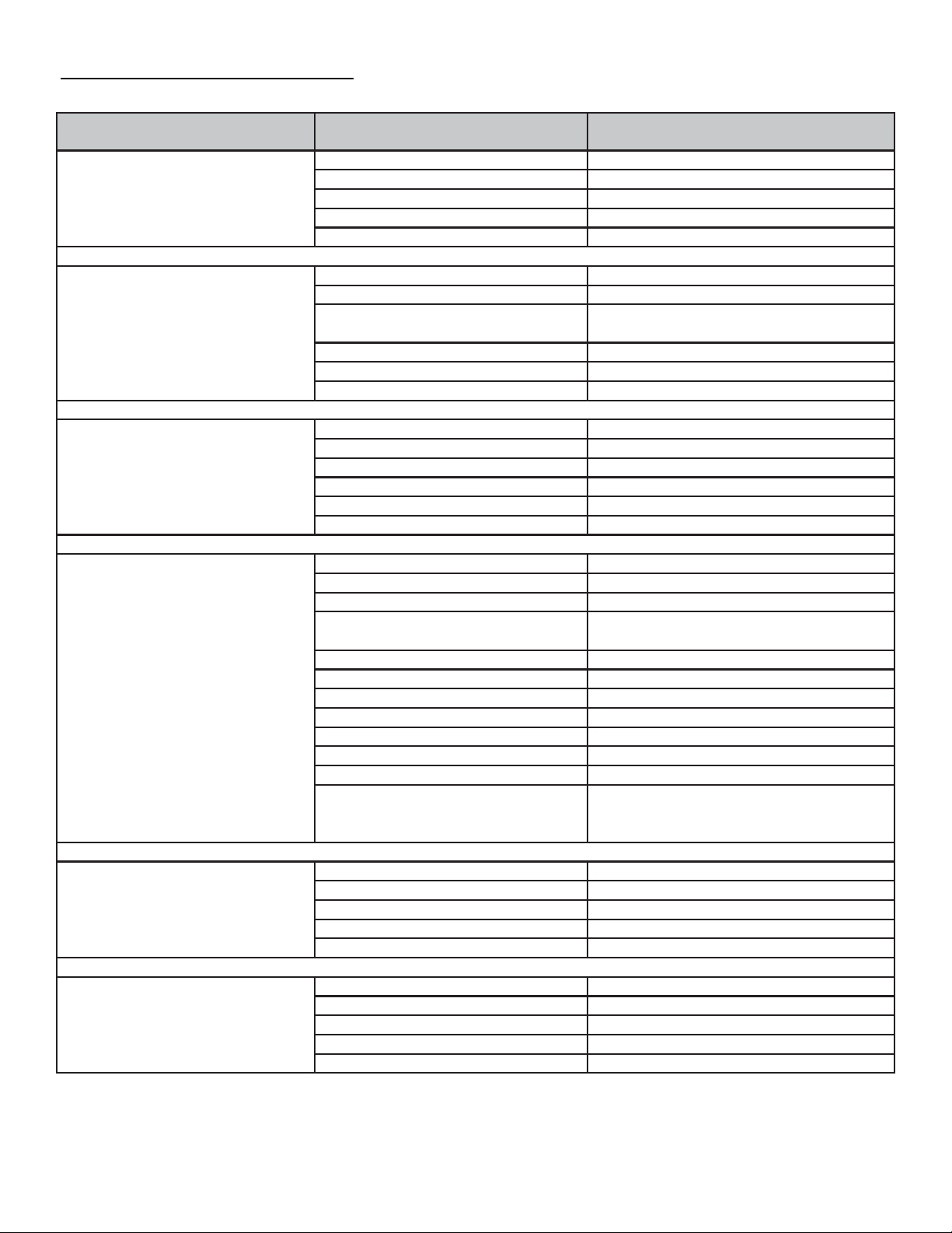
Problem Cause Solution
Excessive pressure loss in sys-
tem
Bypass valve not completelyopen Opencompletely
Pipe diameter to small Increasediameter
Piping system has to many tie ins Redesign pipe system
Leaks in piping system Fix leaks
In line filter element clogged Replacefilter element.
Water downstream of dryer
Bypass valve not completelyclosed Close bypass valve
Air not going through dryer Open inlet valve completely
Under high flow conditions pressure
dropssignificantly Redesign compressed air source and
check pipe diameter.
Auto drain plugged or not working. Clean drain or replace
Dryer to small for inlet air flow Replace dryer or reduce inlet flow.
No pre filter in system Install pre filter
Evaporatorpressure is to
high or to low.
Inlet air temp is to high Check air compressor after cooler
Air cooled condenser is clogged Cleancondenser
Expansion valve is defective Replace expansion valve
Refrigerantleak Find leak and fix. Add refrigerant
Pressure gauge is bad Replace with newgauge
Hot gas bypass needs adjusting Adjust valve to correct pressure.
Power is on to the dryer but the
dryer will not start
Fuse is bad Check for short, fix and replace fuse
On/Off switch defective Replaceswitch
No power going to dryer Check circuit breaker and power supply
Power going to dryer is incorrect Make sure power source and data la-
bel match.
Contactordefective Replace with a new one
Over load relaydefective Replace with a new one
Capacitordefective Replace with a new one
Start relaydefective Replace with a new one
Pressure switch defective Replace with a new one
Temp switch defective Replace with a new one
Compressordefective Replace with a new one
High Pressure switch is open
Low pressure switch is open
Thermostatopen
Find reason and reset
Evaporator Temp is to low
Hot gas bypass valve needs adjusting Adjust or replace
Evaporator pressure gauge bad Replace
Capillarytube blocked Replace
Temp or Pressure reset set to low Reset
Refrigerantleak Find leak, fix it and ad refrigerant
Evaporator Temp is to high
Ambient temp to high Improve ventilation in area
Hot Gas valve needs adjusting Adjust or replace
Condenser blocked or plugged Cleancondenser
Flow is to high going in dryer Change air compressor
Compressor valves are damaged Replacecompressor
TROUBLE SHOOTING GUIDE

11
UA40
UA55
MHT25
UA20
UA25
TECHNICAL SPECIFICATIONS

12
UA200-3,4,5
MHT130-3,4,5
UA75
UA100
UA125
UA150
UA200-1,2
MHT40
MHT60
MHT75
MHT100
MHT130-1,2

13
UA250
UA300
MHT150
UA400
UA500
UA625
MHT200

14
UA800
UA1000
UA1200
UA1600
UA2000

15
DATA LABEL—UA Series
Note - Data below is for reference only and is subject to change. Please refer to the label on your unit
for the most up to date information.

16
DATA LABEL—MHT Series
Note - Data below is for reference only and is subject to change. Please refer to
the label on your unit for the most up to date information

17
ELECTRICAL SCHEMATICS
UA20A; UA25A; UA40A; UA55A
MHT25A
UA75A; UA100A; UA125A
MHT40A; MHT60A; MHT75A
UA150A; UA200A; UA250A; UA300A
MHT100A; MHT130A; MHT150A

18
ELECTRICAL SCHEMATICS
UA200A
UA250A
UA300A
MHT130A
MHT150A

19
ELECTRICAL SCHEMATICS
UA400A
UA500A
UA625A
UA800A
UA1000A
UA1200A
MHT200A

20
ELECTRICAL SCHEMATICS
UA1600A
UA2000A
This manual suits for next models
99
Table of contents
Other Altec AIR Dryer manuals