American Innovations MicroMax GPS360 User manual

© 2018 American Innovations, Ltd.
Required Tools
Voltmeter Windows®Laptop PC
Bullhorn®Tools configuration software
USB to mini-USB cable
Optional Tools
(Continued)
1 of 4
Derating Table
CAUTION: Metal relay casing on the MicroMax GPS360 will get hot. Allow 5 - 10 minutes after interruption
stops before handling the unit.
CAUTION: Do not connect the MicroMax GPS360 to primary mains power.
WARNING: Before beginning any wiring to the MicroMax GPS360, ensure that power has been turned off at
the rectifier.
GPS360 Installation & Configuration
Quick Reference Guide
CAUTION: The MicroMax GPS360 is set to use Normally Closed relays by default. If you plan to use a
Normally Open relay, check the Options > Ouput Parameters menu to ensure the interrupter is configured to
the desired relay setting (refer to Page 4).
NOTES FOR GPS360
1On power up, the unit will stay on as long as it takes to acquire a GPS signal. Once it acquires a 3D fix, it takes approximately two minutes
to synchronize to GPS time and automatically enter the main menu or a previously loaded interruption program.
aThe unit will not go to sleep while in this mode, which could potentially drain the battery. The unit must get a GPS lock to enable
power saving features. You can bypass the GPS screen by pressing PREV.
2The unit will turn off the LCD screen (power save mode) 60 seconds after the last key press. If an interruption program was not selected
to run, the unit will enter deep sleep mode 5 minutes after the last key press.
3While an interruption program is running, the unit will enter power save mode but continue to interrupt. You can press a key at any time
to check the status of the interruption program.
aWhen using start/stop or daily interruption modes, the unit will go into deep sleep during non-interruption hours. Press any key to
“wake up” the unit (see 1a).
bIf you wake up a unit from power save mode during interruption, it takes two minutes for the GPS to resynchronize. The unit will
continue interrupting during resynchronization.
4To put the unit in deep sleep mode, press and hold the PREV key until the screen flashes (approximately 10 seconds) then release the key.
Part No. 122234-000, rev0
Setup 1 — GPS360 with magnets installed; not in contact with rectier cabinet; any interruption cycle.
Setup 2 — GPS360 with magnets removed; with heatsink surface in good contact with rectier cabinet; any interruption cycle.
Ambient Temperature Maximum Current (A)
Celsius Fahrenheit Setup 1 Setup 2
25 C
35 C
45 C
55 C
65 C 149 F
95 F
113 F
131 F
77 F83
76
66
56
42 65
80
90
100
100

(Continued)
2 of 4
MicroMax GPS360 Quick Reference Guide
Part No. 122234-000, rev0
February 2018
1To interrupt the AC power:
Connect Relay to Rectifier
GPS360 Relay
Connected to
Rectifier Positive
2To interrupt the DC power:
NOTE: These connections are not polarity sensitive.
b Slide shrink wrap tube
(provided) onto the second
GPS360 relay cable.
d Wrap assembly with
shrink wrap to prevent
equipment shorting.
GPS360 Relay Cable & DC
Output Cable
aRemove the tap change bar from the taps.
bConnect the two GPS360 relay wires to the taps.
NOTE: Connect relay wires to the same taps
that were connected by the change bar.
c Connect the GPS360 relay
cable to the DC output cable
using available hardware.
aDisconnect the DC output cable. Then connect one of
the GPS360 relay cables to output.
GPS360 Relay Cable & DC
Output Cable Wrapped
GPS360 Relay Connected to
Rectifier AC
CAUTION:Do not connect the MicroMax GPS360 to primary mains power.
NOTE: See Step 3on page 3 for instructions on connecting the GPS360 to rectifier line power and/or if using an
external relay.
Ensure that power is turned off to the rectifier.
NOTE: If installing the GPS360 on a bond, the relay wires must be connected in series with the two structure wires,
one from each of the pipelines.
2
GPS360 Power Source
1
Tap Change Bar
1If line power is available, use an external power source, such as one of the following:
aThe rectifier — with power turned on to the rectifier, use a voltmeter to locate a power source across any
two available AC taps. The GPS360 require 8 - 42 V AC.
bA 120 V AC convenience outlet with the 12 V DC wall adapter.
cA USB cable connected to a computer.
2If no line power is available, use the internal battery on the unit.
The following procedures are general steps for a typical installation. For specific instructions, see the MicroMax Interrupters
User Guide (part no. 122204-000) available from your website account under the Help menu.
Installing the Equipment

(Continued)
3 of 4
© 2018 American Innovations, Ltd.
MicroMax GPS360 Quick Reference Guide
Part No. 122234-000, rev0
External Relay and Line Power
Connect GPS Antenna Cable to GPS360
3Connect red/white twisted wire cable to INPUT
connection on Power Cable. Then clip alligator clips
to rectifier AC taps. Voltage range is 8 - 42 V AC.
1Connect GPS antenna cable to GPS360 GPS
Antenna connection.
2Place GPS antenna outside of rectifier in an
area with a clear view of the sky.
1Connect Power Cable to the GPS360
Power connection.
GPS360 Power Connection
2Connect relay control or coil to Power Cable
OUTPUT. Be sure to observe proper polarity,
especially if a flyback diode is present on a
mercury relay coil. Power Cable
OUTPUT
Alligator Clips
on Rectifier Taps
Power Cable
Twisted Wire Cable Connected to Power Cable
NOTE: If you are using the internal battery and relay, skip this step. The GPS360 has to be connected to line
power when using an external relay.
GPS Antenna GPS360 GPS
Antenna Connection
4
3
WARNING:Ensure that the antenna connection does not come into contact with any conductive surface of the rectifier.
GPS Antenna
Connection
Power
Relay
Cables
GPS Antenna
Connection
Power
Relay
Cables

Part No. 122234-000, rev0
February 2018
4 of 4
MicroMax GPS360 Quick Reference Guide
Program MicroMax GPS360
NOTE: While the GPS360 battery is charging, a
displays in the top right corner. When the unit is
fully charged, the icon is replaced by a full
battery icon .
Set Up Interrupter
Configure Programs
battery icon .battery icon .
5
1 For Interruption, enter a number between 1 and 9 for the program
number.
aPress to select interruption schedule - Daily, Continuous,
or Start/Stop.
b Use and to move through fields; use keypad to change settings.
c Press to load program.
Press to select interruption schedule - Daily, Continuous,Press to select interruption schedule - Daily, Continuous,
Use and to move through fields; use keypad to change settings.Use and to move through fields; use keypad to change settings.
Press to load program.Press to load program.
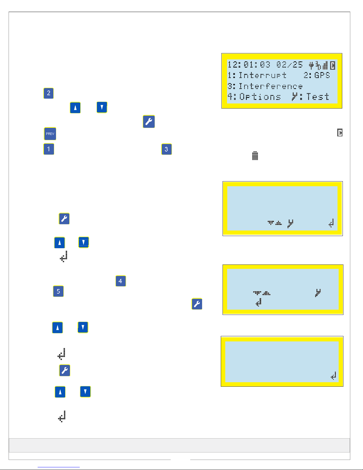
1Power on the rectifier.
2Power on the unit by pressing any button on the keypad..
3Press to view GPS information.
4Press and hold and to change display contrast.
5OPTIONAL: From the main menu, press to run Test Mode.
Press to return to main menu.
6Press to set up an Interruption program OR
to set up an Interference program.
From the main menu, press to run Test Mode.From the main menu, press to run Test Mode.
to change display contrast.to change display contrast.
Press and hold andPress and hold and
Press to set up anPress to set up an
Press to view GPS information.Press to view GPS information.
Interruption Program
# 5 On 12
.0 Off 03.0
Start 06:00 01/01/14
Stop 18:00 12/31/99
Change: / Set:
/ Set:
3For Interference:
aUse and to move through fields. Use keypad to
change settings.
bPress to select type of interruption.
cPress to select interruption schedule - Daily, Continuous,
or Start/Stop.
dUse and to move through fields; use keypad to change
settings.
ePress to load program.
to move through fields; use keypad to changeto move through fields; use keypad to change
Switch: Norm Closed
Int. Cycle: ON/OFF
Move: Change:
Done: Cancel:PREV
Done:
Move:
Move:
Move:
Done:
Done:
Out Parameters
#10 On 13.0 Off 05.0
Delay 002.0
Cycle Time 0088s
Unit #07/10 Next:
Interference Program
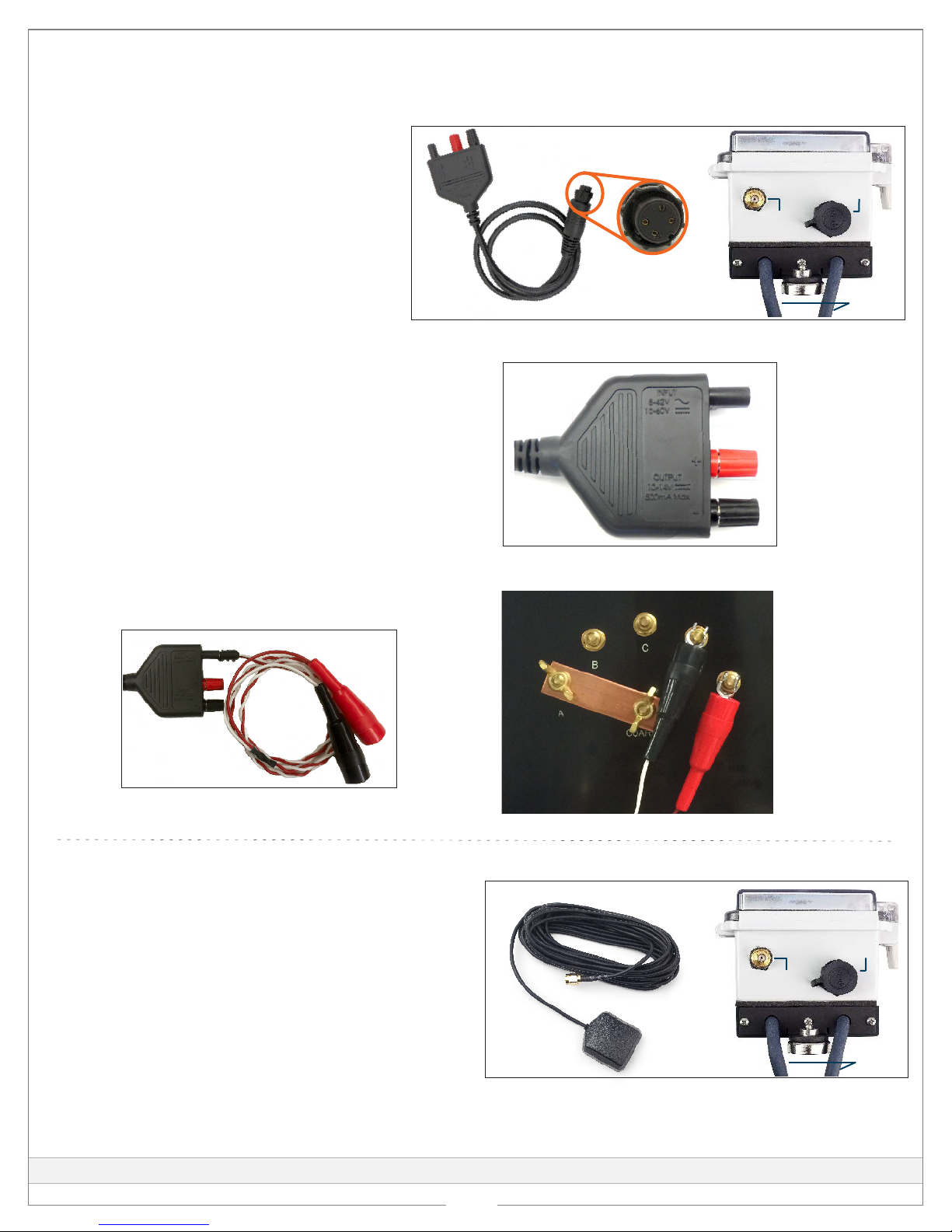
The following procedures are general steps for programming the GPS360 using the unit keypad. For instructions
on programming the unit with Bullhorn Tools, refer to the online help available from the Bullhorn Tools Help
menu or to the MicroMax Interrupters User Guide.
GPS360 Main Menu
NOTE: When adjusting the UTC offset (time-zone), the unit must resynchronize with satellites, which can take up to 2 minutes if
reliable GPS signal is established.
2For Interruption Output Parameters:
aFrom the main menu, press to access a list of Options and
then to view or edit Switch and Int. Cycle options.
bTo change settings, move cursor to the option and press .
When finished, close and lock the clear cover on the GPS360. Place interrupter inside the rectifier.
Table of contents
Popular GPS manuals by other brands

MARLINK
MARLINK SMALLTRACK user guide

Delphi
Delphi NA10000-11B1 - Mobile Navigation - GPS... user manual

MGL Avionics
MGL Avionics EFIS G2 Guide to using

Prentke Romich Company
Prentke Romich Company NuEye user guide

Unique-sky
Unique-sky UB-353 user guide

Adventure Pilot
Adventure Pilot iFly 700 owner's manual