American Musical ReMOTE SL User manual

Rev - 1.1
CONTENTS
1. Introduction
2.Connecting the ReMOTE SL
2. 1 Using the SL as a MIDI interface
2. 2 MIDI I/O within the sequencer
2. 3 Advanced routing options
3. Controlling with the ReMOTE SL
3. 1 PLAY Mode – Template Setup and Use
3. 2 Program/Bank change and Tempo control
3. 3 Factory Preset Template Layout –
Manual and Automap Modes
4. Automap Mode
4. 1 Controlling Reason 3 using Automap
4. 2 Controlling Cubase SL/SX 3 using Automap
5. Assigning controls on the ReMOTE SL
5. 1 EDIT Mode
5. 1. 1 Template Parameter Edit 1 Page – CC Messages
(all controls)
5. 1. 2 Template Parameter Edit 1 Page – NRPN Messages
(all controls)
5. 1. 3 Template Parameter Edit 1 Page – RPN Messages
(all controls)
5. 1. 4 Template Parameter Edit 1 Page – SYSEX Messages
(all controls)
5. 1. 5 Template Parameter Edit Sysex String Page –
SYSEX Messages (all controls)
5. 1. 6 Template Parameter Edit 1 Page – MMC Messages
(just buttons/trigger pads/pedals)
5. 1. 7 Template Parameter Edit 1 Page – NOTE Messages
(just buttons/trigger pads/pedals)
5. 1. 8 Template Parameter Edit 1 Page – BANK CHG Messages
(just buttons/trigger pads/pedals)
5. 1. 9 Template Parameter Edit 1 Page – PROG CHG Messages
(just buttons/trigger pads/pedals)
5. 1. 10 Template Parameter Edit 1 Page –
DRUMNOTE Messages (just trigger pads)
5. 1. 11 Template Parameter Edit 1 Page – TEMPLATE Messages
(just buttons/trigger pads/pedals)
5. 1. 12 Template Parameter Edit 1 Page –
PITCHBND Messages (just Touchpad/joystick)
5. 1. 13 Template Parameter Edit 2 Page –
pots/encoders/sliders
5. 1. 14 Template Parameter Edit 2 Page – buttons/trigger pads
5. 1. 15 Template Parameter Edit 2 Page – Touchpad
5. 2 Assigning the X/Y Touchpad
5. 3 Trigger Pad assignment
5. 4 Restoring Templates
5. 5 Saving Templates
5. 6 Using a sustain/expression pedal
5. 7 Editing the Transport buttons
5. 8 TEMPLATE Mode
5. 9 Keyboard Zones
6. GLOBAL Mode
6. 1 Saving GLOBALS
6. 2 Updating the OS
7. WRITE
8. TAP TEMPO
9. GLOSSARY
10. TROUBLESHOOTING
11. APPENDIX I - SPECIFICATIONS
APPENDIX II - MIDI IMPLEMENTATION CHART
APPENDIX III - APPROVALS INFORMATION

1. INTRODUCTION
Welcome to the ReMOTE SL User Guide! Here you’ll find detailed explanations of all operational features of this revolutionary controller
keyboard. If you are reading the User Guide, it is assumed that you have already read the Getting Started Guide for the SL and, as such,
have a basic knowledge of the fundamental workings of the unit. However, to remind yourself of the meaning of various terms and phrases,
there is a comprehensive Glossary (section 9).
It is also important to point out that continual product improvements from the day of release mean that some areas of the Manual may
have been changed by the time of reading. If you find the operation of the SL contradicts the Manual at any stage then it could be due to
a product update. The best way to stay up to date with the latest product developments is to visit the ‘Product Updates’ section on the
subheading bar of the home page of www.novationmusic.com.

2. CONNECTING THE REMOTE SL
As explained in the Getting Started Guide, the MIDI class compliant nature of the ReMOTE SL makes setting up incredibly simple.
To control software (fig.1), just connect to the computer using the supplied USB lead and you’re ready to go (power will be supplied over
USB). Similarly, if wanting to control a single piece of MIDI hardware, like a sound module (fig. 2), then just insert 4 C-size batteries or
attach an external power supply (Novation PSU-6, not supplied) and a MIDI cable to get going.
Fig. 1 ReMOTE SL connected to a computer Fig. 2 ReMOTE SL connected to an external MIDI instrument
(Batteries inserted)
Computer
USB cable
USB port
Midi cable Sound Module 1
Midi Out 1
Midi In

2. 1 Using the SL as a MIDI Interface
The following sections are a guide to more advanced MIDI setups with the SL.
The multiple MIDI connections on the rear panel of the SL mean that the unit can be used as a MIDI interface, to send data from
a sequencer to external MIDI equipment, whilst using the SL to control plug-ins running within the session. Simply connect the SL to
a computer over USB in addition to connecting to the sound module using a standard MIDI cable (Fig. 3).
Fig. 3 ReMOTE SL connected to a computer and an external MIDI instrument
For this setup to work, the MIDI information being received by the SL must be sent to the relevant MIDI output. This is done by routing the
data correctly within the SL Global settings. For example, if the output in the sequencer MIDI track is set to input 1 of the SL (USBa – see
section 2. 2 for details) then this will need to be sent to the relevant MIDI Out port on the rear panel. In this case of Fig. 3 this will be MIDI
Out Port 1 (M1); so USBa should be set to M1. To access the page where these settings can be made, press the GLOBAL button, followed
by the SCROLL UP button to the left or right of the screens. For a more detailed explanation of the GLOBAL Menu, refer to section 6 of
this Guide.
If wanting to use the SL to control plug-ins within the sequencer but not the attached sound module in the setup above (Fig. 3), the MIDI
data being sent by the SL when buttons are pushed or keys played will need to be sent to the USB ports (USBa and/or USBb – see section
2.2 for details) but not the MIDI Port 1 Out of the SL (M1). This is set up in either of the Template Edit Menus, Template Individual (EDIT
Mode) or Template Common (TEMPLATE Mode), depending on the complexity of the SL’s Template settings. For a more detailed explanation
of MIDI routing options, refer to section 5.1.1 of this Guide.
Computer
USB cable Midi cable Sound Module 1
USB port Midi out (M1)

2. 2 MIDI I/O within the sequencer
Inside the sequencer, the SL will display 2 MIDI In Ports (called SL In Ports 1 and 2) and 3 MIDI Out Ports (called SL In/USB Ports 1-3).
This is because the USB interface is like a standard 2 Out (from the SL) 3 In (to the SL) MIDI network. Both Inputs and two of the Outputs
are configurable on the SL, listed as USBa and USBb (or Ua/Ub) in the various Edit Menus. The third MIDI Output is the Port with which
the sequencers communicate with the SL during Automap Mode and so is not an option for transmitting MIDI data from the sequencer
to external devices. The following diagram represents the MIDI data flow between the SL and the sequencer:
Fig. 4 ReMOTE SL Data Flow USB-MIDI

2. 3 Advanced routing with the SL
As the ReMOTE SL has two USB MIDI In ports and two USB MIDI Out ports (Ua and Ub), as well as two hardware MIDI Out ports,
complex MIDI setups are possible. Here is an example of one such setup with instructions on how to configure the SL for it:
Fig. 5 - Sequencer running 32 plug-ins with 3 external sound modules also connected
In this example, the SL is controlling 16 different MIDI Instruments (plug-ins) on MIDI channels 1-16 on the SL USB Port 1 (USBa) and
another 16 on MIDI channels 1-16 on the SL USB Port 2 (USBb). So, if a Native Instruments Pro-53 is number 28 in that list, then the
output port for all controls on the Pro-53 SL Template will need to be sent to MIDI channel 12 and Port USBb. All assignable controls within
a factory preset Template will already be set to the Template Common MIDI Channel (‘ComnCHAN’) and Port (‘ComnPORT’), rather than
having an individual routing. This means that all the controls in that Template (all the assigned knobs, buttons, sliders etc.) can be set to the
same routing simultaneously, without having to change each control’s settings individually. To configure this, just press the TEMPLATE button
whilst the Pro-53 Template is selected, which will access the Template Common Menu:
(TEMPLATE Common Parameter Edit Screen)
On this screen, the Common MIDI channel and port can be set to 12 and USBb (Ub), respectively, as shown. Note that the Keyboard
MIDI channel and port should also be set identically.
Computer
Sequencer
(running 32
Midi instruments)
USB cable Midi cable Sound Module 1 (Midi Channel 1)
Sound Module 2 (Midi Channel 2)
Sound Module 3 (Midi Channel 3)
USB port (M1) (M2)
Midi In
Midi In
Midi In
Midi Thru
VELCURVE
1
AFTERTCH
ON
KEYBCHAN
12
KEYBPORT
Ub
COMNCHAN
12
COMNPORT
Ub

If wishing to control sound module 2 connected to MIDI Port 1 Out of the SL (M1), the SL Template settings for that module would need
to make sure that control and key data was sent to port M1 on MIDI channel 2, as follows:
(TEMPLATE Common Parameter Edit Screen)
This assumes that all individual controls within the Template are set to ComnCHAN and ComnPORT (see section 5.1.1 for details), as follows:
(Template Parameter EDIT Screen for all controls within Template)
If wanting to send MIDI data from an additional track within the sequencer to sound module 1 and a further track to sound module 3,
then those MIDI tracks should have their outputs set to SL IN Port 1 (on MIDI channel 1) and SL IN Port 2 (on MIDI channel 1), respectively.
The USBa/b routing within Global settings on the SL should then be set as follows:
(GLOBAL Parameter Edit Screen)
VELCURVE
1
AFTERTCH
ON
KEYBCHAN
2
KEYBPORT
M1
COMNCHAN
2
COMNPORT
M1
CONTROL
CC
DISPTYPE
0-127
LOW VAL
0
HIGH VAL
|127
PORTS
ComnPORT
MIDICHAN
ComnCHAN
CC NUM
0
Mem Prot
OFF
USBa To
M1
USBb To
M2
Midi InTo
|Ua M1 M2
Pot Mode
PICK-UP
DispTime
250 MS
KeepVals
OFF
Midi Clk
INTERNAL

3. CONTROLLING WITH THE REMOTE SL
3. 1 PLAY Mode – Template Setup and Use
As mentioned in the Getting Started Guide, the ReMOTE SL powers up in PLAY Mode, with the DATA/SELECT encoder having the function
of scrolling through the onboard Templates, as shown by the illuminated Template LED. The default Template on powering up can be chosen
by saving the GLOBAL settings with that Template selected (see section 6. 1 for details). Rotate the DATA/SELECT encoder to move to
another Template, viewing the Template number on the left screen and the name on the right. To view the currently selected Template,
hold down the PLAY Mode button.
Pressing the OCTAVE UP/DOWN buttons whilst the PLAY Mode button is held down will change the Template Common MIDI Channel (see
the TEMPLATE Mode section, 5.8, for details).
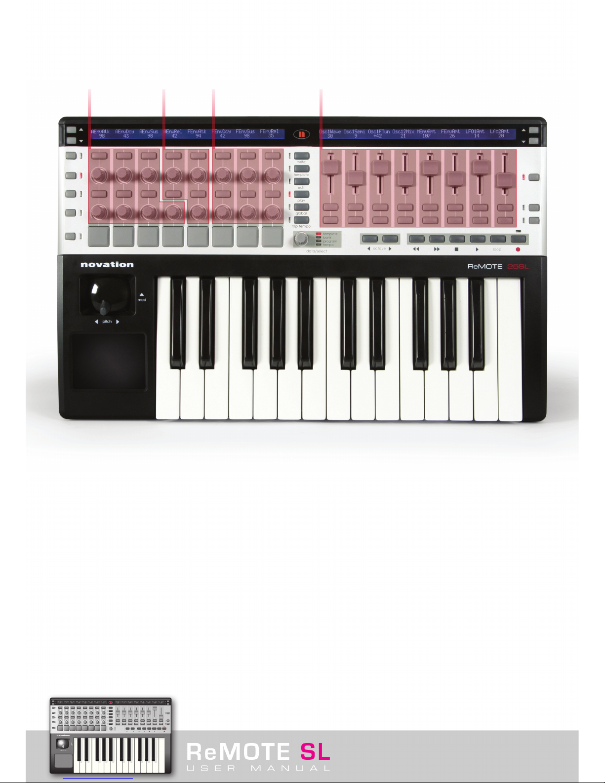
When a Template is selected, the parameters assigned to the currently selected row of controls (knobs/buttons/sliders/pads) on either
side of the unit will be displayed on the screen above. The currently selected row is indicated by the lit LED alongside it. To call up a different
row of controls, press the ROW SELECT button next to it. However, when a control in a row not currently selected is moved, that row of
controls will become the selected row automatically. Furthermore, if controlling a plug-in with multiple onboard Templates, for example the
Novation V-Station with three Templates (one for each oscillator), then the ROW SELECT buttons have an additional function. Pressing the
ROW SELECT button will scroll through the three Templates, effectively giving the impression that one Template is in use and each row of
controls has three values assigned to it (as in Automap mode, see section 4). This means that you can control the V-Station’s three
oscillators without having to scroll through Templates on the SL (instead it’s done for you when you press the ROW SELECT button with any
of the three Templates selected). The Group position of the currently selected Template is displayed at the left hand edge of the left screen
(e.g. Numbers 1-3 for V-Station Templates 1-3, respectively)
Pressing any of the SCROLL UP/DOWN buttons next to each of the SL’s screens changes the information displayed. Pressing SCROLL UP
once will display the MIDI data assigned to the currently selected row of controls, e.g. CC 78. Pressing SCROLL UP twice will show the
routing of that data, e.g. ComnPORT/ComnCHAN. Note that these screens are for display purpose only. Therefore, the CC number of a
control cannot be changed and moving a control (slider/encoder etc.) will have the same action as expected in default PLAY Mode. To
change the value assigned to a control, go to EDIT Mode (see section 5.1).
If a Template you are using doesn’t seem to work properly, it may be because a learn procedure needs to be carried out first. Check the
Template notes in section 3.3 for details.
3. 2 Program/Bank change and Tempo control
The DATA/SELECT encoder has four functions in PLAY Mode. It can be used to scroll through onboard Templates, send Program or Bank
change messages or MIDI Tempo data. Press the encoder to switch between these four modes, with the currently selected one indicated
by the corresponding LED. For example, if wanting to change the program (patch/preset sound) on a soft synth currently being controlled
then press the DATA/SELECT encoder until the program LED is illuminated, then rotate the encoder. The Program Change data sent by
the encoder whilst rotating is displayed on the right hand screen. Similarly, if wanting to send a Bank Change message (to change the MIDI
Sound Bank on the soft synth), press the encoder until the bank LED is lit and then rotate the encoder.
If wanting to send a Tempo change message to a sequencer, such as Reason, press the DATA/SELECT encoder until the Tempo LED is
illuminated. Now the encoder can be rotated to send a message, which will increase or decrease the Tempo of the track. The Tempo
change message will be routed to whatever ports are selected on the BPM Message To option of the GLOBAL Miscellaneous Edit Page (see
section 6 for details).

3. 3 Factory Preset Template Layout - Manual and Automap Modes
The majority of onboard Templates are for controlling synthesizers and so they adhere to a standard layout, as follows:
This means that when you call up a different instrument, whether using Manual Templates or Automap Mode, the envelopes and filter
controls will generally be in the same place for ease of use. Some layouts are different, however, due to the diversity of plug-ins on the
market. Here is a breakdown of the onboard (Manual) Templates, detailing any deviations from the standard layout above. Automap
Templates follow the same layout but without buttons as these are not currently available in Cubase Automap mode:
V-Station - Manual Templates
Location in Remote SL : Templates 1, 2 and 3
Title : V-Station 1,2 and 3
Three manual templates are used to create the V-Station Mapping. Controls for the Arpeggiator are positioned on the buttons below the
sliders on the right.
Bass-Station - Manual Template
Location in Remote SL : Template 4
Title : Bass Station
One template is used to create the Bass-Station Mapping since there are only a few controls. No controls are available for individual
Oscillator levels on the Bass Station so Encoder 1 controls the Osc Mix level.
Click on any row of buttons, pots, encoders or sliders to find out what
they control within the standard synth template layout
Oscillator’s LFO’s Filter’s Envelope’s

FM7 - Manual Template
Location in Remote SL : Template 5
Title : FM7
Envelopes and filters are in the normal place, top left rotary knob changes the operator and the other controls are specific to the
selected operator.
There is an FM7 setup file ‘REMOTESL.F7c’ on the Resources CD, which must be loaded into the FM7 for the Template to work.
To load the file into the FM7, click on the controller ‘LOAD’ button in the master section of the FM7. Navigate to the file ‘REMOTESL.f7c
and open it. Note this can then be saved to the c:/program files/native instruments/FM7/assigns folder where C: is the hard drive that
the FM7 is installed on. From the FM7 preferences option, make sure that the following options are checked:
1 MIDI controller range 000-127
2 0...63: off 64...127: on
3 Use OP A controllers for selected op
4 OP Select controller: 9
5 Use 3 CCs for ratio.
Pro53 - Manual Templates
Location in ReMOTE SL : Templates 6 and 7
Title : Pro 53
Follows the general synth template loosely. Additional Osc controls below the Main Osc section, extra LFO and other controls on
the buttons.
The Pro 53 uses a learn facility to remember controllers. The controller values assigned to the Pro-53 template can either be learnt by the
Pro 53 or a preference file 'ReMOTESLPro53.txt' can be imported from the Resources CD into the Pro-53. To import the text file, click on
the NI logo on the Pro 53, select ‘Load Controller Map’ and then navigate to the file.
Battery 2 - Manual Template
Location in Remote SL : Template 8
Title : Battery
Drum Pads for the first 8 cells. Sliders are for output volume for each battery instrument.
B4 - Manual Template
Location in Remote SL : Template 9
Title : B4
Top row of rotary pots for Lower Manual with 'fully out' on the buttons above. Sliders are for Upper Manual with "fully out" on buttons below.
Lower row of pots and buttons for other controls.
Kontakt II - Manual Template
Location in Remote SL : Template 10
Title : Kontakt II
Only global volume, tune and pan for the first 8 instruments (MIDI channels 1-8)
ImpOscar - Manual Templates
Location in Remote SL : Templates 11 and 12
Title : ImpOscar 1and 2
Two manual templates are used to create the ImpOscar Mapping. Controls for the Arpeggiator are positioned on the buttons below
the sliders on the right.
Oddity - Manual Templates
Location in ReMOTE SL : Templates 13 and 14
Title : Oddity 1 and 2
Follows the general synth template but with additional Osc Controls below the main Osc section and HPF control on the bottom row.
VCA and VCF velocity amounts are on the right sliders.

Minimonsta - Manual Templates
Location in Remote SL : Templates 15 and 16
Title : Minimonsta 1and 2
Mainly follow the general synth layout. Main changes are on the top row of rotaries: template 1 deals with Osc1 and LFO, template 2
with Osc 2 and 3.
MS-20 - Manual Template
Location in Remote SL : Template 17
Title : MS-20
Follow general synth layout. Osc 2 controls are on the buttons below Osc 1.
Poly6 - Manual Templates
Location in ReMOTE SL : Template 18
Title : Polysix
Cut down version of the general synth layout. Arpeggio controls are on the right sliders and buttons.
LegacyCell - Manual Template
Location in Remote SL : Template 19
Title : LegacyCell
Encoders 1-8 are on the top row of rotaries. Sliders are on the sliders!
CS-80V - Manual Templates
Location in ReMOTE SL : Templates 20 and 21
Title : CS-80V-1/2
The CS-80 has two onboard Templates. Templates 1 and 2 correspond to OSC 1 and 2 respectively. Filter cutoff and resonance have
separate controls for the HPF and LPF on each OSC. Therefore, Cutoff and Res for both the HPF and the LPF are assigned, HPF directly
above LPF.
The corresponding 'controlMidi' file in the CS-80 folder on the Resources CD must be placed in the following directory, where C is the
hard drive the Arturia plug-in is installed on:
C:\Program Files\Arturia\CS-80\save
And on a Mac:
> Library > Preferences > Cs80V > save > controlMidi
Arp2600V - Manual Templates
Location in ReMOTE SL : Templates 22 and 23
Title : Arp2600V-1/2
The ARP 2600 V has two onboard Templates. The only difference between the 2 Templates is the Osc controls. Templates 1 and 2
correspond to OSC A and B respectively.
The corresponding 'controlMidi' file in the Arp2600V folder on the Resources CD must be placed in the following directory, where C is
the hard drive that the Arp2600V is installed on:
C:\Program Files\Arturia\ARP2600 V\save
And on a Mac:
> Library > Preferences > arp2600v > save > controlMidi

Albino - Manual Templates
Location in Remote SL : Templates 24 and 25
Title : Albino 1 and 2
Two manual templates are used to create the Albino Mapping. Controls for the Arpeggiator are positioned on the buttons below the
sliders on the right.
In order for the Albino Templates onboard the SL to work, the file ‘Albino.mod’ on the Resources disc needs to be imported into the Albino
plug-in. To do this, take the following actions:
1. Click the ECS (Easy Controller Setup) button next to the ALBINO 2 logo within the plug-in
2. Select Load
3. Navigate to ‘Albino.mod’ in the Resources folder on the Resources disc and click Load
Z3ta - Manual Templates
Location in Remote SL : Templates 26, 27 and 28
Title : Z3ta 1,2 and 3
Mainly follow general layout. The three templates cover all oscillators and a most envelopes and LFOs.
Z3ta has two learn files: midic00.rgc and midicfg.txt. These must be placed in the following location:
> Steinberg > VST Plugins > (rgcaudio >) z3ta+ > midi
Halion - Manual Templates
Location in ReMOTE SL : Template 29
Title : Halion
Cut-down version of the general synth layout.
Vanguard - Manual Templates
Location in Remote SL : Templates 30, 31 and 32
Title : Vanguard 1, 2 and 3
Mainly follow general synth layout. Template 2 gives access to effects on row of pots. Template 3 sliders are for the envelope
modulation amounts.

4. AUTOMAP MODE
Automap mode is a revolutionary new system in which the ReMOTE SL automatically maps instruments and active components within
a sequencer session for you. All you need to do with an Automap-supported application is boot it up and the rest is left to the SL. As
sequencers differ from one to the next, the nature of the SL Automap system varies with each. The following sections give a detailed
description of the Automap system for the two currently supported applications, Reason 3 and Cubase SL/SX 3. If you’re experiencing
any difficulties with Automap or to check for the latest Automap-supported applications visit the ‘Product Updates’ section of
www.novationmusic.com.
4. 1 Controlling Reason 3 using Automap
To control Reason 3 using the SL in Automap mode, the setup procedure on the Resources CD must first be carried out. Insert the disk
and follow the instructions on screen. Then, the SL must be selected as the Control Surface within Reason Preferences. Go to Preferences
in the Reason Menu and select Control Surfaces and Keyboards, then press Add and select Novation as the Manufacturer. Select ReMOTE
SL as the Model and the SL will be ready to use:
The ‘Surface Locking…’ option in the Options Menu should also look like this:

With these settings, the SL will automatically detect when Reason is booting up and will activate Automap mode, mapping all the controls
of the currently active area of the rack. To switch to controlling a different instrument/effect or the Mixer, simply mouse click on the
relevant area of the rack in the MIDI In column as shown:
When a new area of the rack is selected for MIDI control, the SL will automatically map all its controls and display the values on
the screens. For example, when the MIDI In column beside a Subtractor track is clicked then the SL will map its controls as follows:
Then, if the MIDI In column beside a Malstrom track is clicked, the SL will map the Malstrom’s controls as follows:
Notice that many of the controls, such as filters and amplitude envelopes, are mapped to the same logical areas so that when a new
instrument loads the controls are in the same place each time. This way, the SL is like an infinitely expanding virtual instrument!
Additional Reason Automapping information is available at the end of the User Manual.
Click here to read.
Click on any row of buttons,
pots, encoders or sliders to
find out what they control
within the ‘Subtractor’ Synth
Click on any row of buttons,
pots, encoders or sliders to
find out what they control
within the ‘Malstrom’ Synth

4. 2 Controlling Cubase SL/SX 3 using Automap
With Cubase-automapping, the SL works like a universal VST control surface. When the application is loaded, the SL scans all VSTs in the
session and maps their controls to the same logical areas of the SL. This way, no matter which VST is being controlled, controls like filter
frequency will always be in the same place so there are no surprises. The standard layout for VSTs in Automap Mode is the same as that in
Manual Template Mode. However, the limitations of the software are currently such that no buttons on the SL are currently available when
using Cubase in Automap Mode, just encoders, pots, sliders and trigger pads. This may not be true at the time you are reading this Manual
however as the software undergoes continual updating. Check the Product Updates section of the Novation website for the latest SL developments.
See section 3. 3 for a breakdown of how each VST is mapped in the Manual Templates as the VST Automaps are almost identical.
All VST Automaps can be adjusted to suit your needs, should you prefer an alternative arrangement to the one Novation have constructed
for you. This is done with the Template Editor software, which can be found in the Downloads section of the Novation website. Here, a plug-
in map can be made simply by dragging named parameters to the software GUI version of the SL on your computer. See the accompanying
Editor Guide for more information.
In order for Cubase Automapping to work, the SL must be selected as the MIDI controller within Cubase. To do this, select ‘Device Setup’
from the Devices Menu and click the + symbol in the top right of the panel. This should open up a list where Novation ReMOTE SL can be
selected, as follows:
Pot, encoder and slider data is sent down USB Port 2 of the SL in Automap Mode, for controlling VSTs (unless this has been changed in
EDIT or TEMPLATE Mode). Meanwhile, the default setting for keyboard and joystick data is USB Port 1. This means that the Device Setup
for the SL in Cubase needs to have Port 2 selected as its MIDI input/output settings, as follows:

Now, the SL will automatically load the Automap Template when Cubase is booted up and map all active VSTs for you, providing there are
available Automap/vstxml files for them. Then, simply pressing the SCROLL UP/DOWN buttons (either side of the screens) on the SL will
switch between controlling each VST in the session instrument rack with the SL’s rotary controls, sliders and trigger pads. The SL keys and
joystick do not switch instruments when the SCROLL UP/DOWN buttons are pressed as these are determined by the currently selected
track as shown below. Each MIDI track must be setup to receive data on MIDI Channel 1, so that an instrument can be played using the SL
keys and joystick when a track is selected, as follows:
To play an instrument then simply select the corresponding track. If wanting to control that instrument, press the SCROLL UP/DOWN
buttons (if required) until the VST name appears on the right hand SL screen. The ROW SELECT buttons can be used to view the
parameters assigned to a particular row of controls, as well as scrolling through different parameters assigned to that row if more
options are available (three values per control are possible in Automap Mode).
If a VST for which no Automap has been created is selected on the SL, the parameters will still be automatically mapped to the SL but
won’t be laid out in any specific order. Instead, they will all appear in the random order determined by the parameter list provided by the
plug-in manufacturer.
If wanting to create your own Automap (vstxml) files for a VST then download the ReMOTE SL Template Editor from the Novation website
and follow the instructions detailed in the accompanying instructions for use.

5. ASSIGNING CONTROLS ON THE REMOTE SL
5. 1 EDIT Mode
In EDIT Mode, the data assigned to each individual control on the SL (all buttons, pots, encoders, sliders, Touchpad, joystick, Transport
controls, pedals) can be edited. Unlike on previous Novation controllers, the SL’s large screens mean that all Menu pages are displayed
alongside one another so that all information can be viewed simultaneously. The controls below each section of the left hand screen can
be used to modify each value (as described in the Getting Started Guide) and a different control is called up for edit by holding down the
EDIT button and moving the control. The right hand screen displays instructions throughout EDIT Mode.
In this mode, pressing either of the SCROLL UP buttons moves to the second (and third for SYSEX messages) parameter edit screen,
in which the control name and response (e.g. pot and button action) can be set.
If a control has nothing assigned to it, then the first screen will show:
Use the first vertical column of controls to select a type of MIDI data to assign to the control. Buttons step up and down options, whilst
the pot and encoder scroll through them. Pressing the top button or rotating the pot/encoder through one position calls up the first
option, CC (Continuous Controller) Number.
Control
NoContrl
DispType
BLANK

5. 1. 1 Template Parameter Edit 1 Page – CC Messages (all controls)
The options from left to right, after Control type (CC) are:
DispType (Display Type): This option chooses the way in which data is displayed for the control. The options are 0 - 127 and -64 to +63.
For example, if wanting to assign the volume of a track to a pot then 0-127 would be preferable, whereas the pan would suit -64 to +63.
Low Val (Low Value): This option sets the lower limit of the control, which will often be 0 or -64 but in the case of wanting to set a control
to vary from 20 to 30, it would be 20. The values on offer here will be in the range set in DispType. It is possible to reverse the action of
a control by setting a low value that’s higher than the High Val.
High Val (High Value): This option sets the upper limit of the control, which will often be 127 or 63 but in the case of wanting to set a
control to vary from 20 to 30, it would be 30. The values on offer here will be in the range set in DispType. It is possible to reverse the
action of a control by setting a high value that’s lower than the Low Val.
Ports: This option sets the port that the MIDI data for that control is sent out of. There are several options here:
OFF – MIDI data is not transmitted
Ua – Sent to USB Port 1 (SL In 1)
Ub – Sent to USB Port 2 (SL In 2)
M1 – Sent to SL MIDI Port 1 Out
M2 – Sent to SL MIDI Port 2 Out
Ua M – Sent to USB Port 1 (SL In 1) and MIDI Port 1 Out
Ub M1 – Sent to USB Port 2 (SL In 2) and MIDI Port 1 Out
Ua M2 – Sent to USB Port 1 (SL In 1) and MIDI Port 2 Out
Ub M2 – Sent to USB Port 2 (SL In 2) and MIDI Port 2 Out
M1 M2 – Sent to both MIDI Port 1 Out and MIDI Port 2 Out
Ua M1 M2 – Sent to USB Port 1 (SL In 1) and both MIDI Port 1 Out and MIDI Port 2 Out
Ub M1 M2 – Sent to USB Port 2 (SL In 2) and both MIDI Port 1 Out and MIDI Port 2 Out
KeybPORT – Sent to the Keyboard Port (set in TEMPLATE Mode; the Template Common Parameter Edit Menu)*
ComnPORT – Sent to the Common Port (set in TEMPLATE Mode; the Template Common Parameter Edit Menu)*
* The KEYBOARD and COMMON (KeybPORT and ComnPORT) routing options mean that there are two choices of global routing
within a Template. This way, groups of multiple controls within a Template can be routed the same way. This is normally preferable,
unless constructing a Template that controls several different MIDI destinations simultaneously. As such, most controls within factory preset
Templates are set to ComnPORT.
MidiChan (MIDI channel): This option sets the MIDI channel on which the data will be transmitted. This can be set to an individual value
between 1 and 16, or to KeybCHAN or ComnCHAN. These last two options mean that there are two choices of global MIDI channel
settings within a Template. This way, groups of multiple controls within a Template can be routed the same way. This is normally preferable,
unless constructing a Template that controls several different MIDI destinations simultaneously. As such, most controls within factory preset
Templates are set to ComnCHAN.
CC Num (CC Number): This sets the value of the CC Number for the control to a value between 0 and 127. If wanting to view the
CC Num in hexidecimal then press the top ROW SELECT on the left. Pressing the same button again will switch back to standard decimal
display. The display type that is selected here (decimal/hexidecimal) will be carried through into the second control display page in PLAY
Mode, accessed by pressing either of the SCROLL UP buttons.
Control
CC
DispType
0-127
Low Val
0
High Val
|127
Ports
ComnPORT
MidiChan
ComnCHAN
CC Num
0

5. 1. 2 Template Parameter Edit 1 Page – NRPN Messages (all controls)
Changing the first option, Control, to NRPN (Non-registered Parameter Number) displays the following screen:
The first 5 of the subsequent options from left to right on the screen (from DispType to MidiChan) are the same as for CC Numbers,
so refer to section 5.1.1 for details. The last two options are as follows:
NRPN lsb (Least Significant Byte): This page allows the Least Significant Bank controller number of the control to be set (see the Novation
online answerbase for a description of NRPN numbers). This can be set to a value between 0 and 127.
NRPN msb (Most Significant Byte): This page allows the Most Significant Bank controller number of the control to be set (see the Novation
online answerbase for a description of NRPN numbers). This can be set to a value between 0 and 127.
If wanting to view the NRPN lsb/msb in hexidecimal then press the top ROW SELECT on the left. Pressing the same button again will
switch back to standard decimal display. The display type that is selected here (decimal/hexidecimal) will be carried through into the second
control display page in PLAY Mode, accessed by pressing either of the SCROLL UP buttons.
5. 1. 3 Template Parameter Edit 1 Page – RPN Messages (all controls)
Changing the first option, Control, on this screen to RPN (Registered Parameter Number) displays the following screen:
The first 5 of the subsequent options from left to right on the screen (from DispType to MidiChan) are the same as for CC Numbers, so
refer to section 5.1.1 for details. The last two options are as follows:
RPN lsb (Least Significant Byte): This page allows the Least Significant Bank controller number of the control to be set (see the Novation
online answerbase for a description of RPN numbers). This can be set to a value between 0 and 127.
RPN msb (Most Significant Byte): This page allows the Most Significant Bank controller number of the control to be set (see the Novation
online answerbase for a description of RPN numbers). This can be set to a value between 0 and 127.
If wanting to view the RPN lsb/msb in hexidecimal then press the top ROW SELECT on the left. Pressing the same button again will switch
back to standard decimal display. The display type that is selected here (decimal/hexidecimal) will be carried through into the second control
display page in PLAY Mode, accessed by pressing either of the SCROLL UP buttons.
Control
NRPN
DispType
0-127
Low Val
0
High Val
|127
Ports
ComnPORT
MidiChan
ComnCHAN
NRPN lsb
52
NRPN msb
68
Control
RPN
DispType
0-127
Low Val
0
High Val
|127
Ports
ComnPORT
MidiChan
ComnCHAN
RPN lsb
52
RPN msb
68

5. 1. 4 Template Parameter Edit 1 Page – SYSEX Messages (all controls)
Changing the first option, Control, on this screen to SYSEX (System Exclusive) displays the following screen:
The first 4 of the subsequent options from left to right on the screen (from DispType to Ports) are the same as for CC Numbers, so
refer to section 5.1.1 for details. The last three options are as follows:
Length: This option sets the length of the sysex string from 0 to 12, excluding F0 and F7.
DataType: This option sets the data type to one of three options: None, Single or Rolo (Roland checksum). The last option will have fixed
values for Length and DataPsn.
DataPsn (Data Position): This option sets the sysex variable data position of the first byte. This value will be constrained by the Length.
To learn more about Sysex messages refer to the Novation answerbase. However, a brief description is also included in the Glossary.
Setting the control to Sysex activates a third EDIT screen, accessible by pressing either of the SCROLL UP buttons twice.
5. 1. 5 Template Parameter Edit Sysex String Page – SYSEX Messages (all controls)
Here, the data string can be modified by using the buttons below either arrow to move the cursor left and right (with the currently
selected value blinking) and the buttons/encoder/pot below VALUE to change the value.
Control
SYSEX
DispType
0-127
Low Val
0
High Val
|127
Ports
ComnPORT
Length
6
DataType
NONE
DataPsn
0
SYSEX F0 00 00 00 00 00 00 F7
« VALUE »
Table of contents