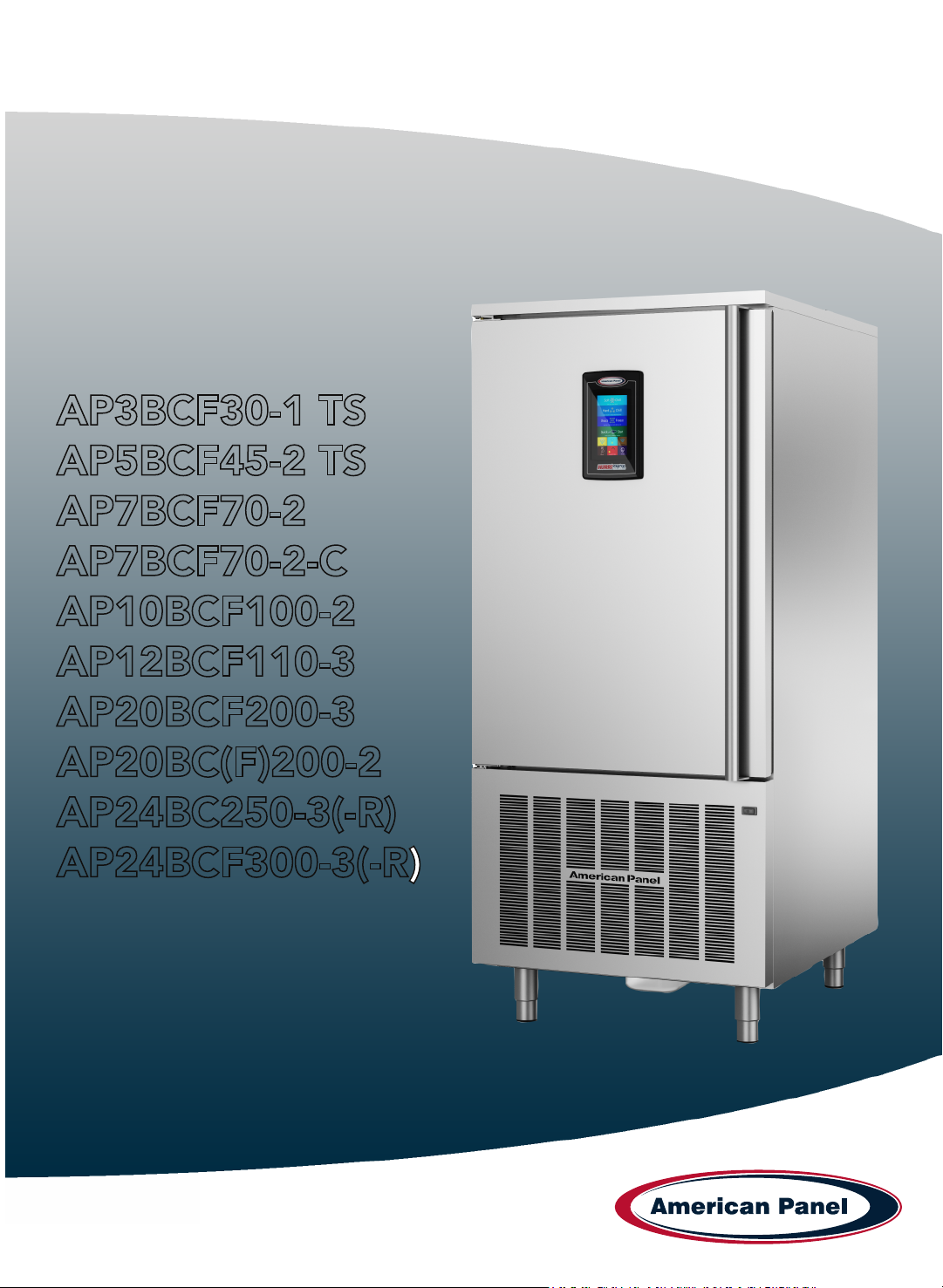
TABLE OF CONTENTS
Warranty...............................................................................................................................
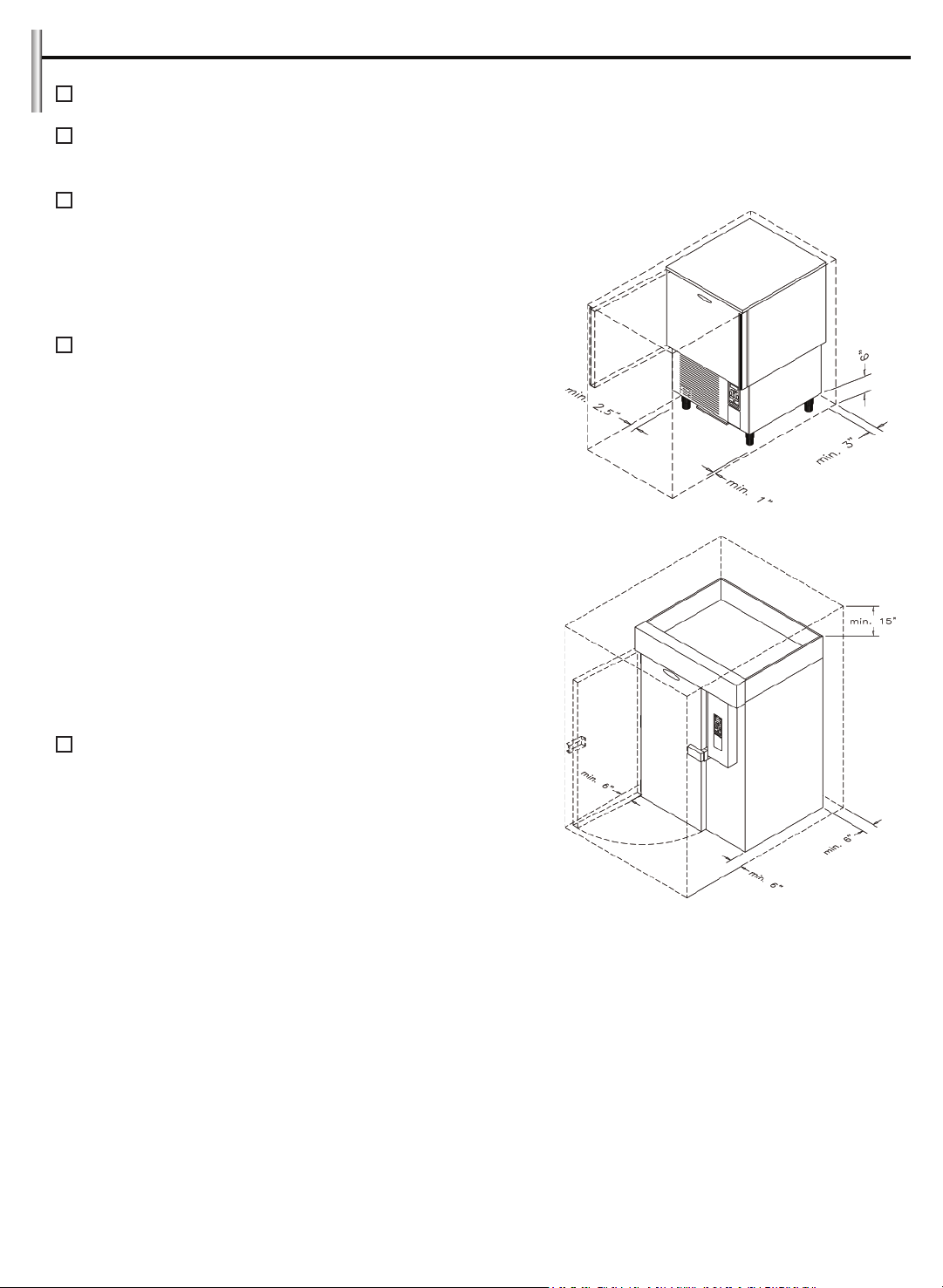
Installation............................................................................................................................
Checking for Proper Installation...........................................................................................
Specifications & Performance...............................................................................................
Modes Explained..................................................................................................................
Cycles Explained...................................................................................................................
- Soft Chill.................................................................................................................
- Hard Chill................................................................................................................
- Shock Freeze...........................................................................................................
- Defrost.....................................................................................................................
- Thaw........................................................................................................................
- UV Sterilization........................................................................................................
- Heated Probe..........................................................................................................
Factory Presets.....................................................................................................................
Unit Operation.....................................................................................................................
- Automatic Mode - Any Cycle................................................................................
- Manual Mode - Any Cycle.....................................................................................
- A la Carte Mode - Any Cycle.................................................................................
- Home Screen.........................................................................................................
- Automatic Mode Screen Explained.......................................................................
- Manual Mode Screen Explained............................................................................
- A la Carte Screen Explained..................................................................................
- UV Sterilization......................................................................................................
- Defrost Cycle.........................................................................................................
- Heat the Food Probe.............................................................................................
- Download HACCP Data.........................................................................................
- Run a Thaw Cycle...................................................................................................
Customizing the Cycles........................................................................................................
General Operating Instructions............................................................................................
- PC Communication Package.................................................................................
- HACCP Download (Peer-to-Peer)...........................................................................
- HACCP Download (via WiFi)..................................................................................
- WiFi Connection....................................................................................................
- Email Configuration...............................................................................................
Maintenance Instructions.....................................................................................................
Evaporator Cleaning Procedure...........................................................................................
Parts List...............................................................................................................................
1
2
3
7
8
8
8
8
9
9
9
9
9
10
11
11
12
13
14
15
16
17
18
18
18
19
19
19
19
20
21
22
23
26
27
28
29