10G200 Series TV • FM High-Gain UHF/VHF/FM
Mast Mount UHF/VHF/FM Amplier
with Switchable FM Trap
Models 10G201 & 10G221 provide up
to 16dB VHF gain and 22dB UHF gain.
Intended for mixed signal areas where
both strong and weak transmissions
are present.
Models 10G202 & 10G222 provide up
to 29dB VHF gain and 29dB UHF gain.
These models are not intended for use
in metro areas, as it could cause signal
overload. Intended for deep fringe areas
where all transmissions are weak.
Amplication is necessary when your
antenna is in weak signal areas, when
it is positioned 100 feet or more from the
TV, or when a single antenna supplies
signals to several units—TVs, VCRs or
FM receivers.
Note:
This unit only amplies signals; it does
not enhance distorted or noisy signals.
FEATURES
Separate Amplier and Power Sup-
ply Units—maximize operational ef-
ciency.
Power Indicator—lights when the am-
plier is operating, and goes out if power
fails or the connecting cable shorts.
Special Automatic Protection Cir-
cuit—guards against cable shorts and
prevents damage to connected receivers.
Surface-Mounted Components—
assure long-term reliability.
Please read and keep all of the in-
structions and warnings contained in
this Owner’s Manual, in the supplied
“Safety Instructions” sheet, and on the
product.
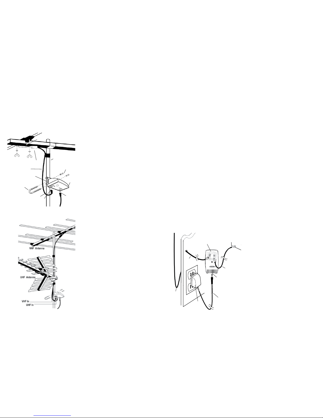
INSTALLATION
Cautions:
• For outdoor antennas, install an an-
tenna grounding system, as shown in
the supplied sheet.
•
The power supply has a protection
circuit that shuts down the amplier
between the power supply and the am-
plier. If the amplier does not operate,
check all connections. Proper operation
should resume when the problem is
corrected.
This symbol is intended to alert you
to the presence of uninsulated dan-
gerous voltage within the product’s
enclosure that might be of sufcient
magnitude to constitute a risk of
electric shock. Do not open the
product’s case.
This symbol is intended to inform
you that important operating and
maintenance instructions are in-
cluded in the literature accompany-
ing this product.
1
3. With the cable disconnected, plug in
the power cord.
4. If the power indicator lights, unplug
the power supply, reconnect the
cable, and plug in the power cord
again. The power indicator should
light again. If the power indicator
still does not light, take the unit to
your local Antennacraft dealer for
assistance.
TROUBLESHOOTING
If you have poor FM radio reception,
be sure FM TRAP is set to OFF.
If the reception is poor on all units
connected to the amplier:
• Be sure the power supply is plugged
into an AC outlet which has power.
• Check all connections between the
antenna, the amplier, and the power
supply.
If you have poor, or no, reception on
only one unit of a multiple receiver
system:
• Check all F-connectors for damage.
In particular, examine the center
pins.
• Be sure the F-connectors are prop-
erly attached.
• Verify that the TV or FM receiver
operates properly when used with
other signal sources.
OPERATION
Using the FM Trap
If you’re having interference problems,
remove the cover plug from the FM
trap on the amplier. If the TV picture
contains wavy or herringbone-patterned
dark lines, slide FM TRAP to ON to re-
duce or eliminate this interference.
If you have the amplier connected to an
FM receiver and a TV, set FM TRAP to
OFF when you listen to the radio.
Note: If FM TRAP has no effect on the
picture, the interference might be from
a source other than FM. You might need
additional traps.
Automatic Protection Circuit
The amplier contains circuitry to guard
against damage caused by a short any-
where in the cable from the amplier to
the receiving unit. A short between the
amplier and the power supply causes
the power supply to shut down automati-
cally, turning off the power indicator and
amplier. If you suspect a short, follow
these steps to correct it.
1. Unplug the power cord and discon-
nect the coaxial cable you suspect is
shorted.
2. Wait 10 minutes for the power supply
to reset. During this time, repair or
replace the cable, and remove any
splitters or other devices that are
between the power supply and the
amplier.
LIMITED 90 DAY WARRANTY
This product is warranted by Antennacraft against manufacturing defects in material and workmanship
under normal use for ninety (90) days from the date of purchase from an Antennacraft dealer. For a
complete version of this warranty, contact your local Antennacraft dealer. If your amplier is not perform-
ing as it should, take it to your local Antennacraft dealer for assistance.
Modifying or tampering with the amplier’s internal components can cause a malfunction and might
invalidate its warranty and void your FCC authorization to operate it.
Antennacraft, P.O. Box 1005, Burlington, IA 52601 10/10
4
Warning: To prevent re or shock
hazard, do not expose this power
supply to rain or moisture.
RISK OF ELECTRIC SHOCK
DO NOT OPEN
CAUTION: TO REDUCE THE RISK OF
ELECTRIC SHOCK, DO NOT REMOVE
COVER OR BACK. NO USER-SERVICE-
ABLE PARTS INSIDE. REFER SERVIC-
ING TO QUALIFIED PERSONNEL.
CAUTION