NOTE:
No
AC
outlet
is
provided
on
units
sold
in
some
areas
owing
to
local
laws
and
regula-
tions.
REMARQUE:
Aucune
sortie
AC
(Courant
Alternatit)
n’équipe
les
modéles
vendus
dans
certaines
régions
en
raison
des
réglements
locaux.
ANMERKUNG:
Aufgrund
6rtlicher
Vorschrif-
ten
und
Gesetze
sind
in
manche
Gebiete
gelie-
ferte
Gerdte
nicht
mit
Wechselstrombuchsen
ausgestattet.
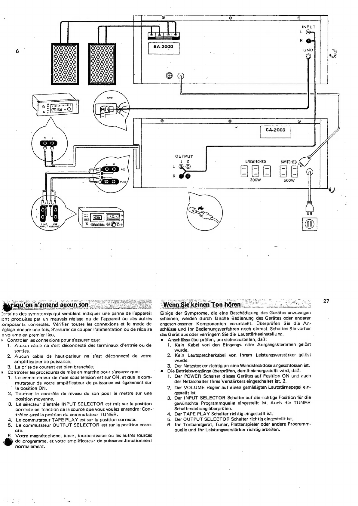
Of
the
five
AC
outlets
provided
on
the
rear
panel,
the
ones
aigrced
SWITCHED
are
controlled
by
the
front-
panel
power
switch.
The
other
ones
marked
UNSWITCHED-are
not
related
to
the
power
switch.
The
former
has
a
capacity
of
500
watts
and
the
latter
300
watts.
Do
not
connect
any
component
whose
power
consumption
exceeds
these
capacities,
as
it is
extremely
dangerous.
The
power
consumption
rating
is
usually
listed
in
the
specifications
or
instructions
of
the
component,
or
on
the
equipment
itself;
be
sure
to
eck the
ratin
:
In
case
aie
have
connected
a
component
to-one
of
the
unit’s
AC
outlets
and
then
another
component
to
the
first
component's
outlet,
be
‘sure
to
add
the
second
component's
rated
power
consumption
to
the
consumption
of
the
component
connected
to
the
unit
itself,
SPECIFICATIONS
7
|
~~7sion
de
sortie
RTIE
1,0
V
(nominale)
(Niveau
de
sortie
maximum:
12
V
avec
pas
plus
de
0,1
%
de
distorsion
harmonique
totale)
TECHNISCHE
EINZELHEITEN
Ausgangsspannung
29
OUTPUT,
1,0
V
(Nennwert)
(Max,
Ausgangspege!
42
V
mit
nicht
mehr
als
0,1
%
Klirrgrad)
TAPE
REC-1,
2
(Stiftbuchsen)
.
150
mV
Enregistrement
de
bande
1,
2
(prises
jacks
a
plot).
TAPE-2
REC/PLAY
(DIN-
Buchse)
.
30
mv
Stee
eee
pte
150
mV
Klirrgrad
20
ee
Weniger
als
0,03%
bei
oder
Enregistrement/reprodyction
de
bande
2
‘Intermodulationsverzerrung
(70
Hz
:
7.000
Hz
=
4:
1
SMPTE
(priseDIN)
..
2...
eee
eee,
30
mV
Methode)
...............
Weniger
als
0,03%
Distorsion
harmonique
totale...
..
.
Moins
de
0,03%
Distorsion
d’intermodulation
(70
Hz
:
7.000
Hz
=
4:
1
méthode
SMPTE
.
moins
de
0,03%
Réponse
en
fréquence
(a
la
sortie
nominale)
.....
0.0
ee
ee
10
Hz
4.80
kHz
tts
dB
Déviation
en
courbe
RIAA
(PHONO)
.
40,2
dB,
—0,2
dB
(20
Hz
a
20
kHz)
Impédance
et
sensibilité
d’entrée
(1
kHz,
pour
sortie
nominale)
Frequenzgang
(bei
Nennausgang):
.
.
.
RIAA-Kurvenabweichung
(PHONO):
10
Hz
bis
80
kHz?%§aB
.
+0,2
dB,
~0,2 dB
(20
Hz
bis
20
kHz)
Eingangsempfindlichkeit
und
Impedanz
(1
kHz,
fiir
Nennausgang)
PHONO-1
2...
0... 0.02
eae
2mV,4
mV,
8
mV/30
kQ,
50
kQ,
100
kQ
(Max.
Eingang:
1V
bei
1
kHz>weniger
als
0,1
%
Verzerrung
und
;
Phonoempfindlichkeitsschalter
(PHONO
SENSITIVITY)
in
PHONO-T
2...
ee
ee
2mV,4
mV,
8
mMV/30
kQ,
Stellung
8
mV}.
50
kQ2,
100
kQ
PHONO-2
2.0...
0.
eee
2
mV/50
kQ
PHONO-2..........00050.
2
mV/50
kQ
AUK
eo
6
ce
sek,
vines
whvng
a
tia
150
mV/50
kQ
(capacité
d’entrée
maximale:
1V
4
1
kHz,
moins
de
0,1%
de
TUNER
..0
0.0.0...
ees
150
mV/50
kQ
distorsion
et
commutateur
de
pepetaits
phono
(PHONO
SENSITIVITY)
a8
mV),
AUX
.
TUNER
BFS
EE
Avleca
Ghai
iy
a
alles
Were
Reproduction
de
bande
1,
2
150
mV/50.k2
150
mV/50
kQ
TAPE
PLAY-1,
2
(Stiftbuchsen)
.
.
TAPE
PLAY-2
REC/PLAY
(DIN-Buchse)
Brummen
und
Stérungen
(IHF)
150
mV/50
kQ
150
mV/50
kQ
PHONO-1,2...........048.
besser
als
75
dB
_
(prisesjacksaplot).......
»
150
mV/50k2
PU
Ne
tas
Ege
Mate
Acie
es
besser
als
90
dB
geproduction/enregistrement
de
bande
2
TUNER
......
whee
vinta
a
as
besser
als
90
dB
(Prise
DIN),
2...
ae
eo
ate
150
mV/50
kQ
TAPE
PLAY-1,2..
0.0...
...
besser
als
90d8
Ronflement
et
bruit
(HF!)
PHONO-1,2
....,
ena
Mieux
que
75
dB
PU
Kee
eects
ga
hc
ees
ds
vee
Bo
helene
Mieux
que
90
dB
ONE
RE
sb
haces
ec
bens
banal
Mieux
que
90
dB
REPRODUCTION
DE
BANDE
4,2
Mieux
que
90
dB