APSCO ARC-30 Operating instructions

INSTALLATION & OWNERS MANUAL
ARC-30
30 GPM MAX
WARNING
BEFORE BEGINNING INSTALLATION OF THIS
APSCO PRODUCT READ AND FOLLOW ALL
INSTALLATION INSTRUCTIONS
REV1 10 -18

Index Page:
Page 3 - Features Included
Page 4 - Figure 1: ARC-30 Dimensions
Page 5 - Installation & Operation
Page 6 - Figure 2: Typical Installation Examples
Page 7 - Figure 3: ARC-30 External Shell Exploded View Accessories
Page 8 - Figure 4: ARC-30 Internal Components Exploded View
Page 9 - Table 1: Parts List
Page 10 - Table 2: Accessories
Page 10 - ARC-30 Repair
Page 11 - Table 4: Trouble Shooting Guide
Page 12 - Figure 5: ARC-30 Repair
Page 13 - Figure 6: Drill Dimensions
WARRANTY
All APSCO, Inc. products are warrantied for 1 year of service,
but in no case more than 2 years beyond the original date of purchase.
APSCO warrants the product as free from defects in materials
and workmanship under normal recommended use.
In order to consistently bring you the highest quality, full-featured products, we reserve the
right to change our specification and designs at any time. APSCO products and logo are the
trademark of APSCO. This document, including textual matter and illustrations, is copyright
protected by APSCO, with all rights reserved.
+1 (918) 622.5600
email: sales@apscopower.com
8178 E. 44th Street, Tulsa, OK 74145
APSCOPOWER.COM
™

FEATURES INCLUDE:
• Stainless Steel Construction
• The basic size of our cooler is 20”X20”X8”, making it the most compact cooler in its class.
• 4 Gallon Hydraulic Reservoir
• Weight: 100 lbs dry, making it the lightest hydraulic cooler in its class
• Flow Rate to 30gpm
• Pressure rated to 3000 psi
• Heat rejection is 20HP at 30gpm with 80°F ETD. This is the highest heat rejection in its class
• Hydraulic filter – This filters your return fluid with a ten micron filter, has an integral bypass valve, and conveniently filters the oil that is added to
the reservoir.
• Filter Element = 10 micron
• Filter Bypass valve- Set at 25 psi. This feature protects the filter from over pressurization due to cold oil or a blocked element.
• System Cold Oil Bypass Valve – Set at 60psi. This feature ensures that the low pressure side of the hydraulic system stays at a low pressure.
Primarily protects from over pressurization due to cold oil.
• System relief valve – This Feature ensures that the maximum system pressure does not go any higher than what you set the valve at. Factory set at
3000psi and is adjustable from 500psi to 3000psi.
• Flow control valve – This feature ensures the delivery of consistent flow to the hydraulically powered cooling blower motor. It is factory set to
ensure the most efficient blower speed.
Page 3

AIR INLET
19.48
20.29
SIGHT LEVEL
7.81
5.50 5.00
MOUNTING STUD
1/2-20 (x4)
HYDRAULIC FILTER
SUCTION -24 SAE
MAGNETIC DRAIN PLUG -8 SAE
GAUGE PORT -4 SAE
RETURN PORT -20 SAE
CASE DRAIN -8 SAE
PRESSURE PORT -16 SAE
2.03in
AIR INLET
Page 4
FIGURE 1: ARC-30 Dimensions

POSITIONING AND MOUNTING:
The ARC-30 is designed to fit in very tight spaces, its narrow profile allows for
behind the cab or frame rail mounting. Unit will ship with a mounting template
to aid in proper installation. (See FIG. 6) The ARC-30 requires at least 1.5” air
gap on the fan shroud side to allow for adequate air intake.
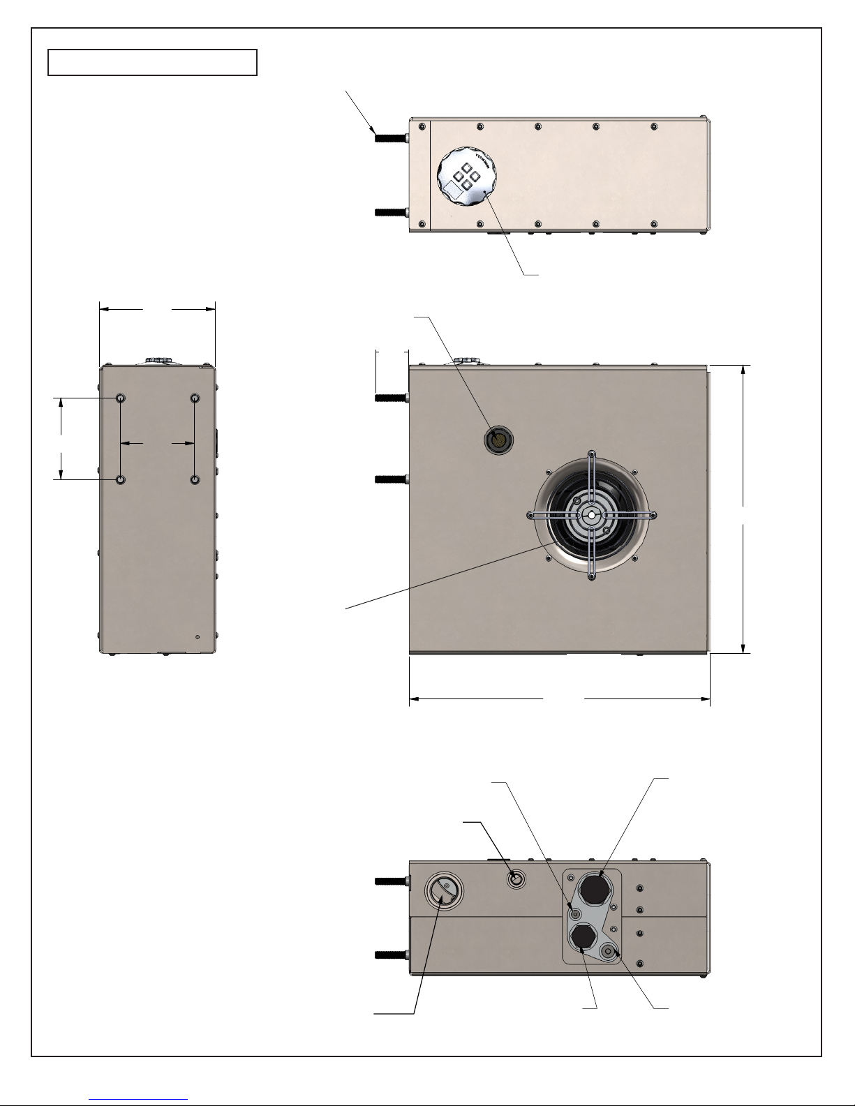
CONNECTIONS (SEE FIG.2):
Note: SAE ports do not require a thread sealant, they seal with an o-ring. Make
sure your SAE fittings have a properly sized o-ring and
are free of thread sealant.
Suction Port-24 SAE – Your hose will go from this port to the
pump inlet port. Minimum hose size – 1.5”.
Pressure Port -16 SAE – The hose from your pump output will “T” into this port.
One side of the “T” supplies the 1.2gpm to the hydraulic fan. Flow will only be
greater than 1.2gpm through this line is if the pressure relief valve setting is
exceeded. The other side of the “T” runs to the motor input or control valve
input depending on your system. Minimum hose size – 1”.
Case Drain -8 SAE – Some hydraulic pumps, motors, and control valves have a
case drain line that needs to be plumbed directly back to the cooler reservoir.
This is where you will make that connection. If your hydraulic system does not
require a case drain line simply leave the APSCO provided hex plug in this port.
Return Port -20 SAE – The hose from the outlet of your motor or control valve
should be plumbed into this port. This port takes all of the return flow from your
motor and sends it through the filter and heat exchanger built into the ARC-30.
Minimum hose size – 1.25”.
Gauge Port -4 SAE – This is a test port on the bottom of your cooler. This port
is connected to the input port of the manifold, for the purpose of connecting
diagnostic equipment like a gauge or transducer to system pressure.
Magnetic Drain Plug -8 SAE – This is where you will drain the cooler reservoir
to change the hydraulic fluid.
START UP PROCEDURE:
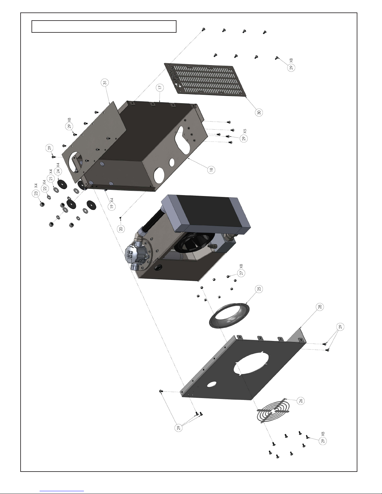
This Unit comes ready to install, no assembly required.
Make up all hydraulic connections.
Remove Filter cap from top of cooler, leave filter in place
and add fluid until it reaches middle of the sight glass
with the PTO disengaged. This will filter the fluid as it is
being added. Even new hydraulic fluid should be filtered.
You will need to add hydraulic fluid in slowly because the
filter is in place.
Bleed air from lines and check fluid level again. Ensure that the lines are full of
fluid and the air is bled from your system, some pumps and motors, particularly
piston will be ruined in a matter of seconds if operated without fluid.
Depending on the length and diameter of the system hoses you may need to add
fluid to the reservoir several times.
Install filter cap.
Slowly engage PTO with engine at idle speed.
Check for hydraulic leaks and repair as needed
Check for fan operation. Note that the fan will turn slowly when system
pressure is low.
Recheck reservoir fluid level. Each time you add fluid disengage PTO, if the
reservoir gets completely empty before you add fluid you will need to bleed air
from the lines again.
Pressure relief valve setting – The ARC-30 pressure relief valve is factory set
to 3000psi. This is a good setting if all of your other system components are
rated to at least 3000psi. Failure to set the relief valve 200psi higher than
system pressure or any other system
relief valve will result in excess build up
of heat. If you need to adjust the APSCO
pressure relief valve it can be accessed
by removing the cooler side cover and
manually adjusting with an Allen wrench.
The change in pressure is roughly 150psi/
quarter turn. Any time the side cover is
off the PTO should be off as well.
Once you verify system functionality with
no leaks and the proper fluid level your
ARC-30 is ready for operation.
SYSTEM MAINTENANCE:
Filter – Unscrew filter cap (use a screw
driver or tool with a square shank) and
replace element every three months.
Fluid – Check fluid level daily (with the
PTO off the fluid level should reach the middle of the sight glass). Drain and
replace hydraulic oil every 6 to 12 months depending on use.
Recommended Fluid – Use non foaming hydraulic fluid and see Pump and Motor
Manufacturer recommendations.
Clean Radiator – Use a mild cleaner compatible with aluminum. Be careful not
to damage fins if using a power washer to rinse cleaner off of radiator. Visually
inspect daily and clean if necessary.
INSTALLATION & OPERATION
Page 5
Warning: High Pressure oil can cause severe
injury. Turn off PTO and bleed pressure
before servicing hydraulic system.
Warning: heavy object. To avoid muscle
strain or back injury, use lifting aids and
proper lifting technique when removing or
replacing.
Warning: Rotating Fan Blade. Can cause
serious injury or cut. Keep hands clear. Turn
off and lockout unit before servicing.
Caution: Surface May be Hot. Ensure PTO is
off and unit has cooled before servicing.
ROTATE CLOCKWISE TO
INCREASE PRESSURE RELIEF
SETTING (INTERNAL HEX)
9/16” JAM NUT. LOOSEN
T0 ADJUST. TIGHTEN WHEN
PROPER RELIEF PRESSURE
HAS BEEN ACHIEVED
PRESSURE RELIEF
VALVE. FACTORY
SET AT 3000PSI

Air Inlet Air Discharge
Compressor
Hydraulic Motor
Hydraulic Pump
Return
Pressure
Suction
Tee
Air Inlet
Air Discharge
Directional
Control Valve
Optional Accessories (Table 2)
Hydraulic Pump Return
Processing Pump
Pressure
Suction
Tee
Hydraulic Motor
Optional Accessories (Table 2)
ARC-30
ARC-30 WITHOUT DIRECTIONAL CONTROL VALVE
ARC-30 WITH DIRECTIONAL CONTROL VALVE
Page 6
FIGURE 2: Typical Installation Examples

FIGURE 3: ARC-30 External Shell Exploded View
Page 7

Page 8
FIGURE 4: ARC-30 Internal Components Exploded View

TABLE 1: Parts List
ITEM NO. PART NUMBER DESCRIPTION Q T Y. TORQUE VALUE REQUIRED TOOL
17596 SHEETMETAL CASE RIGHT 1
27598 SHEETMETAL CASE BOTTOM/BACK 1
37597 SHEETMETAL CASE LEFT 1
47599 CASE, TOP 1
5 7601 SHEETMETAL CASE FRONT 1
67630 INLET RING FOR 225MM IMPELLER 1
77631 FINGERGUARD 1
87812 WHEEL STUD 1/2-20 4
97713 18-8 SS FLAT WASHER 4
10 7715 1/2" LOCK WASHER SS 4
11 7714 1/2-20 NYLON LOCK NUT 4 100 FT. LB 3/4” DEEPWELL SOCKET
12 3786 NUT 1/4-20 NC SS HEX NYLOCK 8 10 FT. LB 7/16” END WRENCH
13 4914 CAPS 10-32 X 1/4 BH SS 1 21 IN. LB 1/8” ALLEN
14 7709 1/4-20 X 5/8" ZINC TORX T27 BUTTON HD 35 10 FT. LB T27 TORX
15 7860 WASHER, RUBBER .5ID X 2.25OD 4
16 7593 MANIFOLD 1
17 7657 SYSTEM RELIEF PILOT OPERATED 1 35 FT. LB 7/8” END WRENCH
18 7664 STRAIGHT THREAD SWIVEL CONNECTOR 1 115 FT. LB 1 7/8” END WRENCH
19 7656 FLOW REGULATOR 8-2 CAVITY 1 25 FT.LB 1 5/16” END WRENCH
20 7726 -08 SAE PLUG 2 40 FT. LB 5/16” ALLEN
21 7644 -04 SAE PLUG 3 13 FT. LB 3/16” ALLEN
22 7594 ADAPTER, MANIFOLD 1
23 7626 HUB, PRESS FIT 1
24 7642 FAN 225MM 1
25 7653 SHCS 3/8"-16 SS 1" LG 3 23 FT. LB 5/16” ALLEN
26 7654 MOTOR MANIFOLD SHCS 5/16"-18 4 13 FT. LB 1/4 ” ALLEN
27 1195 O-RING 2-013 9/16 OD 7/16 ID 4
28 7643 SHCS 8-32 1/2" LG 2 12.6 IN. LB 9/64” ALLEN
29 7592 TANK ASSEMBLY 1
30 7833 HEAT EXCHANGER ASSEMBLY 1
31 7655 COLD START RELIEF VALVE (CHECK) 1 115 FT. LB 1 1/2” DEEP WELL SOCKET
32 7646 12FJ-08MJ STRAIGHT LARGE HEX 1 40 FT. LB 1 1/4” DEEP WELL SOCKET
33 7650 BSPP LOCKNUT (FOR USE WITH SIGHTGLASS) 1 35 FT. LB 1 5/8” SOCKET
34 7660 SIGHT LEVEL PLUG 1" BSPP 1 35 FT. LB 1 1/2” SOCKET
35 6827 HYDRAULIC FILTER ASSEMBLY 1
36 7602 CLEANOUT COVER, TANK 1
37 7662 O-RING 0-258 6 1/4"OD 6"ID(CLEAN OUT COVER) 1
38 7748 O-RING 2-011 IL 7/16OD 5/16ID 8
39 7709 1/4-20 X 5/8" ZINC TORX T27 BUTTON HD 10 10 FT. LB T27 TORX
40 7711 3/8-16 X 1 1/2 SHCS BOLT 18-8 2 20 FT. LB 5/16” ALLEN
41 7710 3/8-16 X 1 1/2" LOCK NUT 18-8 2 10 FT. LB 9/16” END WRENCH
42 7647 16MFS-16MAORB 45 ELB FORG 1 115 FT. LB 1 5/8” & 1 1/2” END WRENCH
43 7648 1" ORFS TUBE NUT 1 115 FT. LB 1 5/8” END WRENCH
44 2574 O-RING 2-220 1 5/8 OD 1 3/8 ID 1
45 1733 O-RING 2-212 1 1/8 OD 7/8 ID 1
46 7815 BARB FTG, SLV END 1
47 7816 BARB FTG, MALE 1-5/16"-12UN 1 115 FT. LB 1 1/2” END WRENCH
48 7817 HOSE, HYD, 1" ID 1
49 7821 BRACKET, TANK MOUNT 1
50 7841 HH 1/4-20 X 2" CAP SCREW 2 10 FT. LB 7/16” END WRENCH
51 4624 O-RING 2-025 1 5/16 OD 1 3/16 1
52 7842 SEALING WASHER, COPPER 2
53 7845 PLUG, #08 SAE MAGNETIC 1 40 FT. LB 5/16” ALLEN
54 7862 O-RING, 2-916 SAE 16 ORB 1
55 7641 HYDRAULIC MOTOR, CW ROTATION 1
Page 9

Page 10
ARC-30 REPAIR:
The design of the Arc-30 will allow you to remove three of the body
panels and pull the internal assembly while leaving the right side
assembly panel mounted to truck (refer to FIG 5, TABLE 3 below). This
is assuming you have left enough room around the heat exchanger
to get to the body panel fasteners. Drain hydraulic fluid from unit by
removing the magnetic drain plug (Item 53, FIG.4), once all the fluid
has been drained replace and torque accordingly. Do not re-use this
fluid. Remove all connections to the ARC30, these connections will
be wet so be sure to have a catch pan for the fluid that will be spilled.
Cap and plug all hoses and ports to prevent contamination. Remove
the front (Item 3) and top case (Item 4), as well as the left side cover
(Item 2). You will also need to remove the three bolts
(Item 5) that fasten the right side case to the manifold. These are
located on the bottom of the Arc-30. You can now remove the entire
inner assembly leaving the right side panel still mounted to the
truck. It is recommended to do any repair work on a clean surface in
a dust free environment. Once the Arc-30 is out of its case you will
be able to remove and replace any of the components. If the repair
requires you to remove the tank mount bracket (Item 49) mark the
position of the bolts on the bracket so you can reinstall in the same
position. This will help ensure that your sight glass and tank cap
will fit concentrically within the case when you put the Arc-30 back
together. When re-assembling the Arc-30 be sure to use blue loc-tite
on all fasteners and torque according to TABLE 1.
TABLE 2: Accessories
ITEM NO. PART NUMBER DESCRIPTION Q T Y. TORQUE VALUE REQUIRED TOOL
56 7855 FILTER ELEMENT, ARC 30 1 SQUARE SHANK SCREWDRIVER
57 7861 CAVITY PLUG, (FOR RELIEF VALVE) 1 115 FT. LB 7/8” END WRENCH
PRESSURE PORT
58 7868 16MJ-16MORB-16MJ RUN TEE 1 115 FT. LB 7/8” END WRENCH
59 7869 16MORB-16MJ STRAIGHT 1 115 FT. LB 1 1/2" END WRENCH
60 7870 16MORB-16MJ 90 1 115 FT. LB 1 1/2" END WRENCH
61 7893 16MORB-16FP STRAIGHT ADAPTER 1 115 FT. LB 1 1/2" END WRENCH
62 7894 16MP-16MP-16MP TEE 1 115 FT. LB 7/8" END WRENCH
RETURN PORT
63 7871 20MORB-20MJ STRAIGHT 1 115 FT. LB 1 7/8” END WRENCH
61 7872 20MORB-20MJ 90 1 115 FT. LB 1 7/8” END WRENCH
65 7895 20MORB-20FP STRAIGHT ADAPTER 1 115 FT. LB 1 7/8” END WRENCH
66 7896 20MP-20MP 90 115 FT. LB 1 7/8” END WRENCH
SUCTION PORT
67 7874 1.5" HOSEBARB - 24ORB STRAIGHT 1 115 FT. LB 2 1/8" END WRENCH
68 7875 2"HOSEBARB - 24ORB 90 1 115 FT. LB 2 1/8" END WRENCH
69 7876 1.5" HOSEBARB - 24ORB 90 1 115 FT. LB 2 1/8" END WRENCH
70 7897 24MORB-24MJ 90 1 115 FT. LB 2 1/8" END WRENCH
71 7898 24MORB-32MJ 90 1 115 FT. LB 2 1/8" END WRENCH
72 7899 24MP-24MP 90 1 115 FT. LB 2 1/8" END WRENCH
73 7900 24MORB-24FP STRAIGHT ADAPTER 1 115 FT. LB 2 1/8" END WRENCH
74 7901 24MORB-32FP STRAIGHT ADAPTER 1 115 FT. LB 2 3/4" END WRENCH
75 7902 32MP-32MP 90 1 115 FT. LB 2 3/4" END WRENCH
76 7903 24MORB-24MP 90 1 115 FT. LB 2 1/8" END WRENCH
CASE DRAIN PORT
77 7877 08MORB-08MJ STRAIGHT 1 40 FT. LB 7/8” END WRENCH
78 7878 08MORB-08MJ 90 1 40 FT. LB 7/8” END WRENCH
79 7904 08MORB-08FP STRAIGHT 1 40 FT. LB 7/8” END WRENCH
80 7905 08MORB-08MP 90 1 40 FT. LB 7/8” END WRENCH
81 7906 08MP-08MP 90 1 40 FT. LB 7/8” END WRENCH
GAUGE PORT
82 7879 04MORB-1/4"FP STRAIGHT 1 15 FT. LB 3/4" END WRENCH
HYDRAULIC DIRECTION CONTROL VALVE OPTIONS
ARC-30 STD Direction Valve Air Assembly Number 20-UNI-1S-03
ARC-30 STD Direction Valve Manual Assembly Number 20-UNI-1S-04
M=MALE, F=FEMALE, P=PIPE OR NPT THREAD, J=JIC 37 ° FLARE, ORB=O-RING BOSS
FITTINGS ARE SIZED IN 16TH" INCREMENTS SO 16=16/16THS OR 1", 8=8/16" OR 1/2", 24=24/16THS OR 1.5"

Page 11
TABLE 4: TROUBLE SHOOTING GUIDE
Problem Cause Corrective Action
Fan not spinning
Low system pressure
Low oil level in tank
Air leak in suction hose or fitting connections
Pinch Bolts (Item 29) are loose or missing
Collapsed Suction Hose
Flow Control Valve (Item 19) has blocked orifice
Fan sucked in road trash such as a plastic bag and has caused fan to
be in a bind
The system pressure must be higher than 900 psi for the fan to spin at
full speed. Slower fan speeds in an unloaded condition are part of normal
operation
Fill Tank, tighten fittings, and bleed air from lines
Tighten fittings and bleed air from lines
Replace and re-torque
Replace suction hose
Remove and clean or replace valve. Change fluid and filter element
With Unit de-energized, remove debris, check for proper torque of pinch bolts.
Check to make sure the fan is not broken or cracked and motor functions
properly
High Oil Temperature
Dirty Heat Exchanger Assembly (Item 31)
System Relief Valve (Item 17) is opening
low oil level in tank
Collapsed Suction Hose
Air leak in suction hose or fitting connections
Clean Heat Exchanger. Use mild cleaner compatible with aluminum. Be
careful not to damage fins when using a pressure washer.
Ensure that valve relief pressure is set higher than your system pressure.
Remove and clean or replace valve. Change fluid and filter element
Fill Tank and tighten fittings
Replace suction hose
Bleed air and tighten fittings
Aeration of oil
(Milky looking oil)
Water Contamination
Air leak in suction hose or fitting connections
Pump is not lower than the tank
Restricted suction line
low oil level in tank
Replace Fluid and Filter Element. Check all fittings and Filter Cap for tightness
Tighten fittings and bleed air from lines
Reposition to ensure the fluid can gravity feed into the pump through the
suction line.
Route suction line to make as straight and short of a run as possible. Ideally
you would want a 1.5” suction line for minimum flow restriction.
Fill Tank and tighten fittings, verify proper fill level before use
Heat exchanger
Assembly leaks
Loose Fittings (Items 48 &18) or cut o-rings (Items 55 & 52)
Burst Heat Exchanger
Replace o-rings and tighten fittings
Replace Cold start relief valve (Item 32) and Heat exchanger assembly (Item
31)
TABLE 3
ITEM NO. PART NUMBER DESCRIPTION Q T Y.
17724 SIDE PANEL ASSEMBLY, RIGHT 1
27723 SIDE PANEL ASSEMBLY, LEFT 1
3 7601 SHEETMETAL CASE FRONT 1
47599 CASE, TOP 1
57709 1/4-20 X 5/8” ZINC TORX T27 BUTTON HD 22

Page 12
FIGURE 5: ARC-30 Repair

5.00
2.695.50
1.41
7.81
T
o
p
o
f
C
o
o
l
e
r
Edge of Cooler
Allow 1.5" minimum
clearance from inlet
DRILL DIMENSIONS
(NOT TO SCALE)
Page 13
FIGURE 6
Minimum 5/8” diameter holes for studs

(918) 622.5600
email: sales@apscopower.com
8178 E. 44th Street, Tulsa, OK 74145
APSCOPOWER.COM
™
Table of contents