Aqua ECO WASH User manual

AQUA eco•wash INTRODUCTION
Dosing system for washing machines ENGLISH
ADSP7000603 rev. 1.3 09/06/2015 37/212
TABLE OF CONTENTS
1.0 INTRODUCTION …………………………………………………………………………………………………………………………… 38
1.1 Standards of reference .......................................................................................................................................... 38
1.2 Technical features ................................................................................................................................................. 38
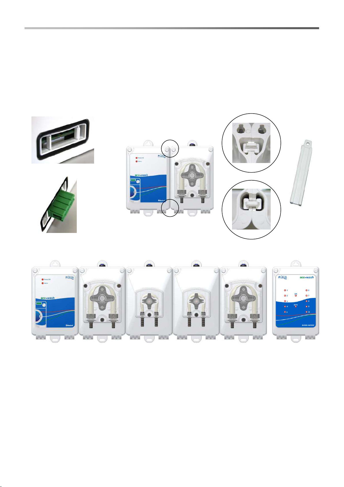
1.3 Package content .................................................................................................................................................... 38
1.4 Installation material ................................................................................................................................................ 38
2.0 INSTALLATION ..................................................................................................................................................... 39
2.1 System assembly .................................................................................................................................................. 39
2.2 Wall mounting ..................................................................................................................................................... 39
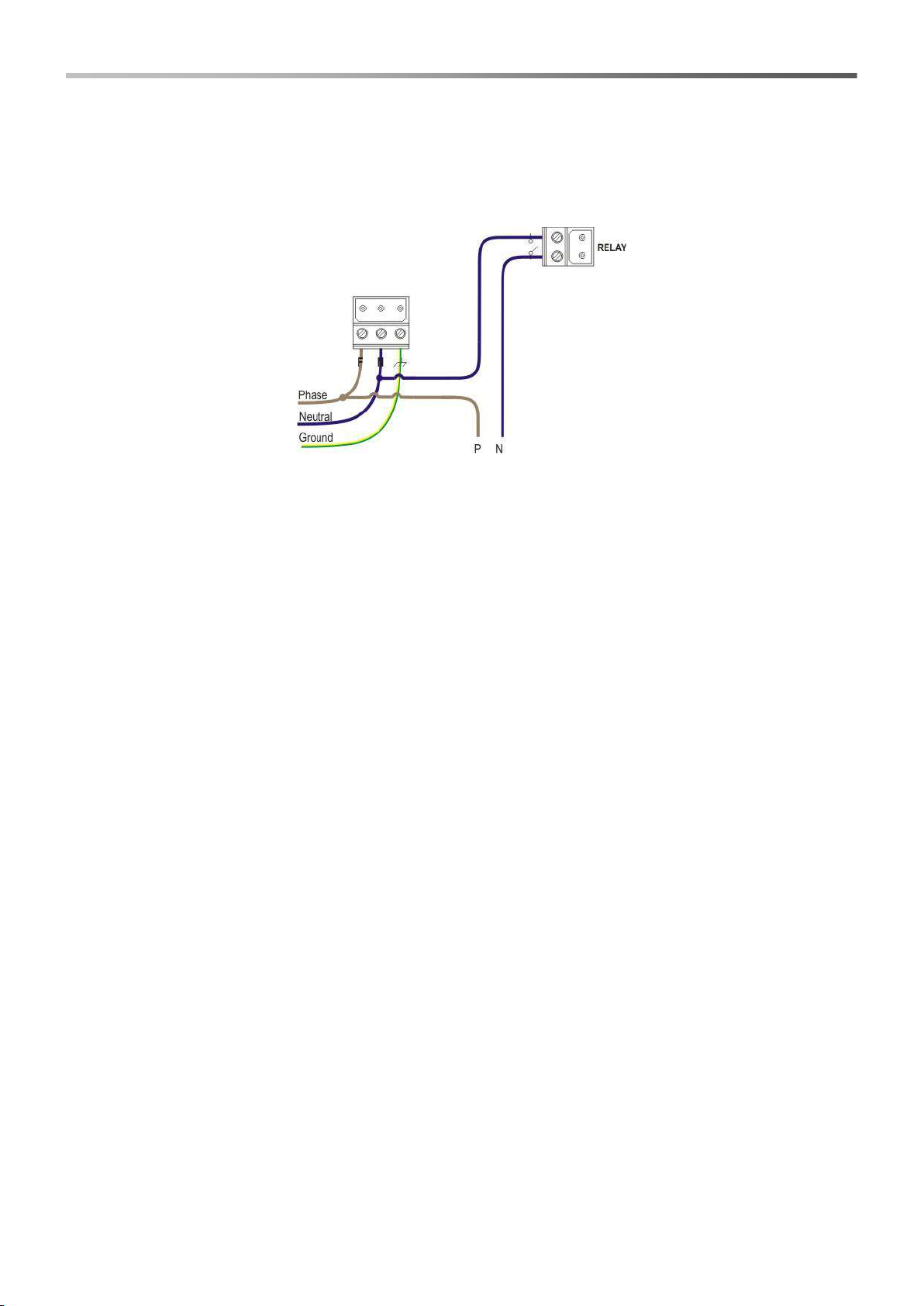
2.3 Electric connections................................................................................................................................................ 40
2.4 Central module electric connections ....................................................................................................................... 40
2.4.1 Power supply.......................................................................................................................................... 40
2.4.2 Flushing kit solenoid valve...................................................................................................................... 40
2.4.3 Flow sensor............................................................................................................................................ 40
2.4.4 Signals module....................................................................................................................................... 40
2.4.5 Relay output ........................................................................................................................................... 41
2.4.6 Alarms output ........................................................................................................................................ 41
2.4.7 Level probe input.................................................................................................................................... 41
2.4.8 Central module LEDS …………..…………………………………………………………………………………. 41
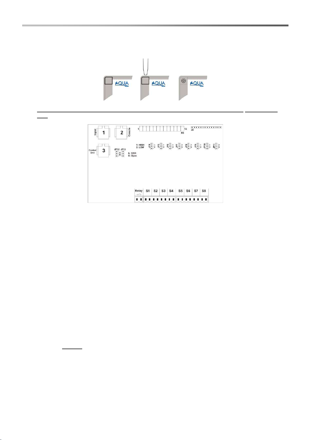
2.5 Signals module electric connections ...................................................................................................................... 42
2.5.1 Console ................................................................................................................................................ 42
2.5.2 Central module ....................................................................................................................................... 42
2.5.3 Washing machine signals ....................................................................................................................... 42
2.5.4 Signals module LEDs ……..…………………………………………………………………………. ................ 42
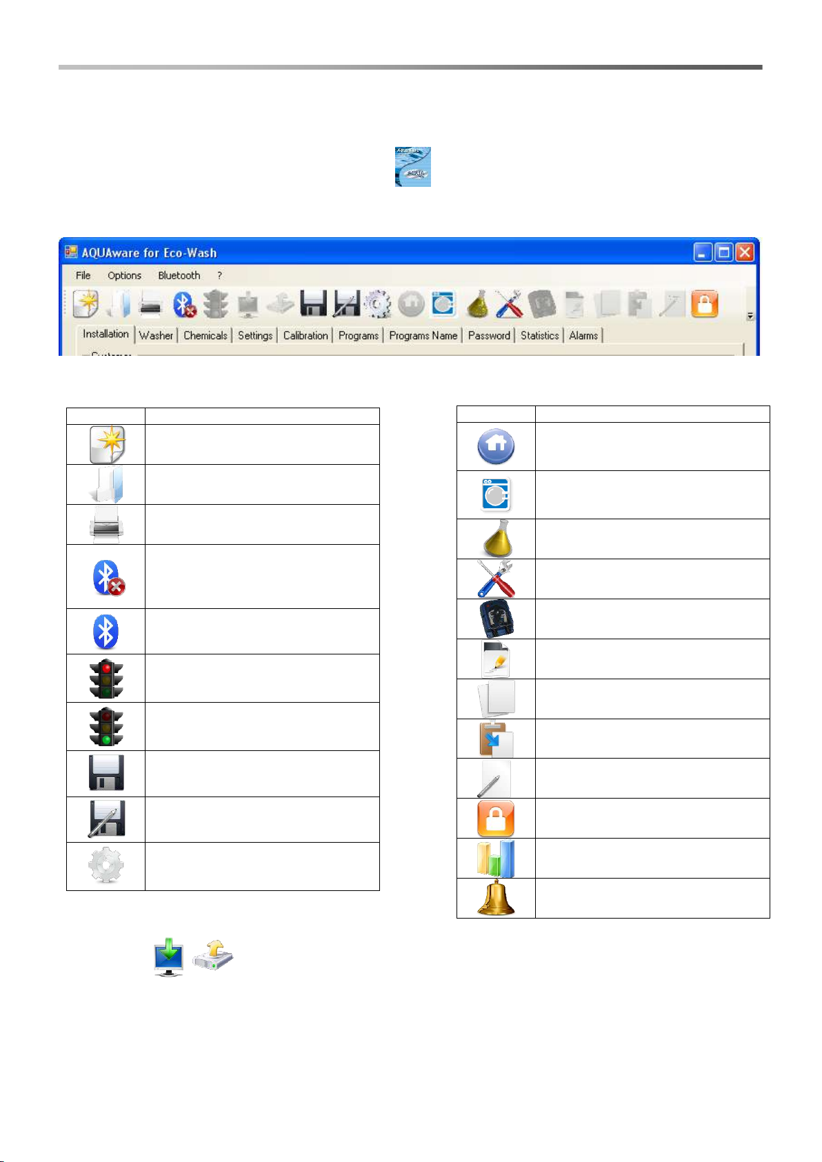
3.0 AQUAWARE CONFIGURATOR PROGRAM......................................................................................................................... 43
3.1 Step 1 –Bluetooth connection................................................................................................................................ 43
3.2 Step 2 –System configuration................................................................................................................................ 44
3.3 Step 3 –System autorecognition............................................................................................................................ 44
3.4 Step 4 –Bluetooth name setting............................................................................................................................. 44
4.0 AQUAWARE PROGRAM ..................................................................................................................................................... 45
5.0 PROGRAMMING ..................................................................................................................................................... 46
5.1 Step 1 –Bluetooth connection................................................................................................................................ 46
5.2 Step 2 –Installation................................................................................................................................................ 46
5.3 Step 3 –Washing machine..................................................................................................................................... 47
5.4 Step 4 –Chemical products.................................................................................................................................... 47
5.5 Step 5 –Settings.................................................................................................................................................... 48
5.5.1 Signals filter .......................................................................................................................................... 48
5.5.2 Drain signal............................................................................................................................................. 48
5.5.3 Flushing.................................................................................................................................................. 49
5.5.4 Autostart................................................................................................................................................. 49
5.6 Step 6 –Calibration................................................................................................................................................ 50
5.7 Step 7 –Programs.................................................................................................................................................. 51
5.7.1 Input signal instruction block................................................................................................................... 51
5.7.2 Pump instruction block............................................................................................................................ 52
5.7.3 Water instruction block............................................................................................................................ 52
5.7.4 Timer instruction block............................................................................................................................ 52
5.7.5 Meter instruction block............................................................................................................................ 52
5.7.6 END instruction block.............................................................................................................................. 52
5.7.7 Conditional instruction block ................................................................................................................. 52
5.7.8 Conditional instruction control block........................................................................................................ 53
5.7.9 RESET instruction block......................................................................................................................... 53
5.7.10 STAT instruction block............................................................................................................................ 53
5.7.11 Connection blocks .................................................................................................................................. 53
5.8 Step 8 –Program names........................................................................................................................................ 54
5.9 Step 9 –Password ................................................................................................................................................. 54
5.10 Step 10 –Statistics................................................................................................................................................. 54
5.11 Step 11 –Alarms.................................................................................................................................................... 55
5.11.1 Alarms setting......................................................................................................................................... 55
5.11.2 Pump maintenance alarm....................................................................................................................... 55
5.11.3 Calibration alarm..................................................................................................................................... 55
6.0 TROUBLESHOOTING ..................................................................................................................................................... 56
7.0 APPENDIX 1 –A few examples of invalid programs............................................................................................................... 57
8.0 APPENDIX 2 –Electric and hydraulic connections................................................................................................................. 58
9.0 APPENDIX 3 –Programming examples................................................................................................................................. 59
9.1 Example 1 ………………………………………………………………………………………………………………………. 59
9.2 Example 2 …………. .............................................................................................................................................. 60
9.3 Example 3 ……………………………………………………………………………………………................................... 61
10.0 APPENDIX 4 –Default settings ………………………………..……………………………………………………………………... 62
11.0 APPENDIX 5–Eco wash system initialization……………………………………………………………………………………………….63
12.0 APPENDIX 6–Multi-machine system ……..……………………………………………………………………………………………….64
13.0 APPENDIX 7–Continuous Washing Machine …………………………………………………………………………………… ………. 68

AQUA eco•wash INTRODUCTION
Dosing system for washing machines ENGLISH
ADSP7000603 rev. 1.3 09/06/2015 38/212
1.0 INTRODUCTION
The eco•wash has been designed for the automatic dosage of chemical products on any type of washing machine,
from the smaller models to the large tunnel machines.
The eco•wash system is able to satisfy every requirement in fact, thanks to the full modularity, we can assemble
up to a maximum of 10 pumps, choosing from the low flow rate (LF model, maximum flow rate of 20 L/H, adjustable
from 0 to 100%) and the large flow rate (HF model, maximum flow rate of 100 L/H, adjustable from 0 to 100%).
Simultaneous can work at maximum three pumps.
The feature making the eco•wash a state-of-the-art system, is the Bluetooth technology enabling easy and full
system management; once the AQUAware software is installed on a PC, provided with the Bluetooth connection
module, it is possible to remotely manage the system. To manage means: system configuration, definition of the
dosing programs and control of the statistics relating to dosages.
1.1 STANDARDS OF REFERENCE
Our pumps are manufactured according to general current Standards and in compliance with the following
European Directives:
n° 2004/108/CE “e s.m.i.
n° 2006/95/CE “DBT Low Voltage Directive” e s.m.i.
n° 2011/65/UE , 2012/19/UE “direttive RoHs e WEEE” e s.m.i.
Pursuant to art. 13 of LD n. 151 dated 25/07/2005 (implementation of Directives 2002/95/EC, 2002/96/EC, 2003/108/EC) it is
notified that:
The electric and electronic devices must not be considered as household waste.
The consumers must, by law, return the electric and electronic devices at the end of their useful life, to adequate differential
collection centres. The crossed out rubbish mean symbol on the product, on the instructions manual or on the packaging indicates
that the product is subject to the disposal rules envisioned by the Standard. Illegal disposal of the product leads to the enforcement
of administrative penalties envisioned by LD n. 151 dated 25/07/2005. By recycling, reusing the material or other forms of utilising
old devices, you are making an important contribution to protecting our environment.
1.2 TECHNICAL FEATURES
1.3 PACKAGE CONTENT
Instructions manual
Central module
Signals module with cable (7 m)
Screws and wall plugs for wall fixing
Modules retainer (2pc)
Green connector for modules interconnection (1pc)
1.4 INSTALLATION MATERIAL
Three-pole cable 3x1.75mm2for power supply connection on central module
Multicore cable 16x0.25mm2for signals connection on signals module
PVC 8x12 tube for hydraulic connections of the pumps
Tube ø12mm for output connection of the flushing stub pipe
Description
Description
Signals
module
HF pump
module
LF pump
module
Relay
module
Console
standard
Levels
module
Power supply
100 ÷
240VAC
50/60Hz
24VDC
24VDC
24VDC
24VDC
24VDC
24VDC
Absorption (max)
130 W
-
-
-
-
-
-
Fuse
4 A DEL
(5x20)
-
-
-
-
-
-
Communications
RS485
RS485
RS485
RS485
RS485
RS485
RS485
Bluetooth
-
-
-
-
-
-
Protection rating
IP65
IP65
IP65
IP65
IP65
IP65
IP65
Dimensions in
mm (LxHxD)
138x230x138
190x120x60
138x230x138
138x230x138
138x230x138
110x85x35
138x230x138
Weight (kg)
1
0,5
2
1,5
1,5
0,25
1

AQUA eco•wash INSTALLATION
Dosing system for washing machines ENGLISH
ADSP7000603 rev. 1.3 09/06/2015 39/212
2.0 INSTALLATION
2.1 SYSTEM ASSEMBLY
1. Lift the lids of the modules composing the system (use a screwdriver to position the screws in opening
position), so all circuits are uncovered.
2. Insert the green connectors (so the writing TOP is legible) on left side of the circuits. Align two modules
and press to realise electric connection between them.
3. Insert the modules retainers in the internal part of the two boxes.
Example of an assembled system with four pumps and the levels module:
Furthermore, it is also possible to mount the levels module (optional) next to the last pump of the
system.
2.2 WALL MOUNTING
Position the eco•wash system on a wall near the washing machine and follow the instructions below:
Install a wall plug and position the upper hole of the central module on it.
Align the system and mark the other holes to be made on the wall (minimum four, two at top and two at
bottom).
Perforate the walls and install the other wall plugs.
Position the system on the wall and fix it.
The maximum height between the eco•wash system and the chemical products tanks must not
exceed 1.5 metres.
1
2
3
4

AQUA eco•wash ELECTRIC CONNECTIONS
Dosing system for washing machines ENGLISH
ADSP7000603 rev. 1.3 09/06/2015 40/212
2.3 ELECTRIC CONNECTIONS
ATTENTION: Before carrying out maintenance on the appliance, always disconnect the power supply.
Using a multimeter, always check all electric connections of the eco•wash system. An incorrect
voltage would cause a damage to the machine that is not covered by warranty. The following manual
must always be kept as reference for any electric connection.
All electric connections must be made in compliance with the prescriptions of the local laws
regarding electric system.
2.4 CENTRAL MODULE ELECTRIC CONNECTIONS
There are two electronic circuits inside the central module, separated by a protection plan. The power supply is in
the low part of the module whereas, all other connections are on the lid.
2.4.1 Power supply
On the power supply boards, connect a voltage between 100 and 240VAC - 50/60Hz on clamp .
2.4.2 Flushing kit solenoid valve –WATER clamps
Connect the flushing solenoid valve (24VDC voltage) on the WATER clamps.
2.4.3 Flow sensor –FLOW METER clamp
Connect the sensor found on the flushing to the FLOW METER clamp, respecting the colours:
Clamp Sconnect the BLU wire
Clamp +5V connect the RED wire
Mass clamp, connect the BLACK wire
2.4.4 Signals module connection –RS485 clamp
Connect the telephone cable coming from the signals module to clamp RS485.

AQUA eco•wash ELECTRIC CONNECTIONS
Dosing system for washing machines ENGLISH
ADSP7000603 rev. 1.3 09/06/2015 41/212
2.4.5 Relay output
The RELAY clamp from a dry contact (not powered); it is possible to program this output in NO (Normally Open) or
NC (Normally Closed).
It is possible to use the RELAY clamp to obtain, for example, a voltage equal to the power supply voltage. The
following figure shows a possible connection to realise such functionality.
2.4.6 Alarm output –OUT 24V Clamp
It is a repeat alarm output that supplies an impulsive voltage (1 second ON and 1 second OFF) at 30VDC with a
maximum absorption of 500mA.
To make the connection, connect the positive on clamp 24V and the negative on clamp S.
2.4.7 Level probe –connection LEVEL clamp
Input for level probe connection. It is also possible to connect more probes in parallel. (contact on/off, without
voltage).
The level input has a programmable filter, 5 seconds by default.
2.4.8 Central module LEDs
The two red LED (Power ON e Alarm) that are on the module lid indicate:
Power ON continuously, it means that the system is powered.
Power ON blinking, it indicates that the system is connected via bluetooth.
Alarm blinking indicates an alarm situation.
Alarm blinking along with Power ON, indicates that you are performing a reset of internal memory.

AQUA eco•wash ELECTRIC CONNECTIONS
Dosing system for washing machines ENGLISH
ADSP7000603 rev. 1.3 09/06/2015 42/212
2.5 SIGNALS MODULE ELECTRIC CONNECTIONS
Open the signals module box; the four screws are behind the wall plugs, which can be easily removed using a
screwdriver. Such operation is shown in the following figure:
When removing the lid, pay attention to the flat LED cable that can disconnect from its connector
(J2).
2.5.1 Console
Connect the console standard cable to clamp 2 or the multipoles cable of the console basic on clamp M3
When connecting with the console standard, make sure the jumper on JP13 is in position A.
2.5.2 Central module
Connect the central module cable to clamp 3 (already assembled).
2.5.3 Washing machine signals –clamps from S1 to S8
Connect the signals coming from the washing machine to clamps S1…8 .
The eco•wash system has 8 optocoupled inputs and compatible with any type of electric signal, alternate or direct.
Also, the system is provided with a jumper for every input (JP4…JP11), that allows us to recognize the level of the
input signal.
HIGH jumper position
This position allows to discriminate signals 110VAC or 230VAC.
LOW jumper position
This position allows to discriminate signals 12VDC or 24VAC.
The chosen position of the jumper must be in accordance with the selection made by the “AQUAware Configurator”
program. This setting is the same for all inputs.
There is no need to respect any polarity for signals in direct.
2.5.4 Signals module LEDs
The signals mdoule LEDs, S1, ..., S8 are blinking when the signal is active (voltage present) and are fixed when
the signal lasts longer than the filter (see par. 5.5.1).
The LEDs (ON and tx / rx) indicate:
ON continuously, it means that the module signals it receives power from the central module.
tx / rx blinking indicates that the active communication between the modules (the flash must be constant)

AQUA eco•wash AQUAWARE PROGRAM
Dosing system for washing machines ENGLISH
ADSP7000603 rev. 1.3 09/06/2015 43/212
3.0 AQUAWARE CONFIGURATOR PROGRAM
Install the “AQUAware Configurator” software.
Launch the program, clicking on icon found on the desktop, the window shown below will appear.
The program allows configurating the assembled system, setting the following parameters:
The number of pumps
The type and flow rates of the pumps
The number of the signals modules
The number and type of console (standard, basic or absent)
With or without the levels module
The system blocks appear coloured differently:
White, the block is present in the system to be configured.
Grey, the block is not present in the system to be configured.
Blue, the block is selected and it is possible to read or vary the block features.
Green, the block has been recognised, therefore resulting correctly configured (see par. 3.3).
Red, the block has not been recognised (see par. 3.3).
3.1 STEP 1–BLUETOOTH CONNECTION
After having pressed icon , a new window will appear in which the following steps must be made:
press Actions and select Radio Bluetooth on
press Actions and select Search devices
Select the name of the device to be connected ("AQUA Eco Wash 01" by default)
press Actions and select Services list
select Serialport
press Actions and select Connect, then confirm connection and finally enter the password, it consists of 4
digits.
The default password is 0000.
It’s possibile to perform another Bluetooth connection, more quickly, following the next steps:
press Actions and select Radio Bluetooth on
press Actions and select Search devices
Select the name of the device to be connected ("AQUA Eco Wash 01" by default)
Double-click on the device and the sistem will be performed simultaneously the search of Services list and
the connection request, so just enter the password (see above).

AQUA eco•wash AQUAWARE PROGRAM
Dosing system for washing machines ENGLISH
ADSP7000603 rev. 1.3 09/06/2015 44/212
3.2 STEP 2–SYSTEM CONFIGURATION
To perfom changes, the system should be paused, the status’s system is indicated by the "traffic light"
icon:
Green light: active system;
Red light: the system is paused;
To change the status of traffic lights, just click the icon.
To configure the assembled system, set the number of the pumps, the number of the signals modules, the type of
console used and the number of the levels modules.
Perform the upload (select BluetoothUpload).
STEP 3–SYSTEM SELF-RECOGNITION
Press the Start button next to system recognition, the pumps blocks will become green if they have been
recognised, otherwise red.
The pumps now start to function one at a time and it is necessary to indicate to the system the number/position of
the pump (pump 1 is that near the central module), by double clicking on the relative block, after which the pump
stops.
When all pump blocks have been recognised, press the End button next to the riconoscimento del sistema (system
recognition).
Pressing "?" opens a window where there are versions of the firmware of all modules of the system
and the software "AQUAware Configurator".
STEP 4–MODULESS CONFIGURATION
Pumps configuration
Select the pump block (P), set the type of pump (LF or HF) and the flow rate expressed in percentage, in the
features of the block.
LF: maximum flow rate 20 l/h
HF: maximum flow rate 100 l/h
Signals modules configuration
Select the signal module block (S), in the blck features it is possible to set the voltage of the electric signals coming
from the washing machine. Its’ possible select one of the following threshold:
▪ 12 Vdc; ▪ 24 Vac; ▪ 110 Vac; ▪230 Vac;
Console configuration
Select the console block (CNS), in the block features it is possible to set the type of console used: standard, basic
or not connected (in the case the system functions in relay mode).
To make the amendments effective, always perform upload (select Bluetooth and then upload
current page).
Levels module configuration
Any parameter to set in this block.
RS485 Configuration
The settings of the RS485 serial configuration are indicated in the bottom-right part of the Configurator program
window.
The indications can be:
S# JP12, in the indicated signals module, set jumper JP12 in position 120 Ohm;
P# JP5, in the indicated pump/relay module, set jumper JP5 in position 120 Ohm;
LEVEL JP9, in the indicated levels module, set jumper JP9 in position 120 Ohm;
We recommend performing these settings to avoid problems with communication between the
various modules composing the system.
3.4 STEP 4–BLUETOOTH NAME SETTING
Set the bluetooth name so that the system is easily recognisable; we recommend entering the name of the washing
machine in which it is installed.
Use names with maximum 16 characters.

AQUA eco•wash AQUAWARE PROGRAM
Dosing system for washing machines ENGLISH
ADSP7000603 rev. 1.3 09/06/2015 45/212
4.0 AQUAWARE PROGRAM
Install the "AQUAware for Ecowash" software.
Launch the program, by clicking on the icon on the desktop, the window below should appear,
showing icons in the upper part and boards in the lower part.
The program allows carrying out all management operations of a project with the following icons:
The two icons will respectively download (from eco•wash to computer) and uploading (from the
computer to eco•wash) of the total data.
BOTH OPERATIONS CAN BE PERFORMED ONLY AFTER YOU PAUSE THE SYSTEM (RED LIGHT), AND THE ELABORATION’S
STATUS WILL BE DISPLAYED BY A "PROGRESS BAR".
ICON
DESCRIPTION
Opens the board relating to the
installation data (name, address,
telephone, etc.)
Opens the board relating to the
washing machine data (brand,
capacity, etc.)
Opens the board relating to the
chemical products data
Opens the board relating to the
eco•wash system settings
Opens the board relating to the
pumps calibration
Deletes the open washing program
Copies the open washing program
Pastes on the open washing
program
Opens the board relating to
entering of the programs names
Opens the board relating to the
system password
Opens the board relating to the
statistics
Opens the board relating to the
alarms settings
ICON
DESCRIPTION
Open a new project with default
settings (see Appendix 4)
Opens a project previously saved
on disc
Prints the statistics and alarms
report
Indicates that the bluetooth
connection is deactivated, clicking
on the icon activates the bluetooth
connection procedure
Indicates the bluetooth connection
is active
Indicates the eco•wash system is
still, clicking on the icon reactivates
it
Indicates the eco•wash system is
functioning, clicking on the icon
stops it
Save the project
Save the project with name
Opens the board of the program
configurations (choice of language
and directory)

AQUA eco•wash PROGRAMMING
Dosing system for washing machines ENGLISH
ADSP7000603 rev. 1.3 09/06/2015 46/212
5.0 PROGRAMMING
The “AQUAware for Ecowash” software enables full management of the eco•wash system. With reference to the
figure below, it is evident how the sequence of the boards under the icons, respects the logic of a typical
installation: Installazione –Lavatrice –Prodotti Chimici –Impostazioni –Calibrazione –Programmi –Nomi
Programmi –Password –Statistiche –Allarmi (Installation - Washing Machine - Chemical Products - Settings -
Calibration - Programs - Programs Names - Password - Statistics - Alarms).
Reported below are the system programming steps.
5.1 STEP 1–BLUETOOTH CONNECTION
Connect Bluetooth by pressing the icon . A new window will now open in which the following operations
must be performed:
press Actions and select Radio Bluetooth on
press Actions and select Search devices
Select the name of the device to be connected ("AQUA Eco Wash 01" by default)
press Actions and select Services list
select Serialport
press Actions and select Connect, then confirm connection and finally enter the password, it consists of 4
digits.
The default password is 0000.
It’s possibile to perform another Bluetooth connection, more quickly, following the next steps:
press Actions and select Radio Bluetooth on
press Actions and select Search devices
Select the name of the device to be connected ("AQUA Eco Wash 01" by default)
Double-click on the device and the sistem will be performed simultaneously the search of Services list and
the connection request, so just enter the password (see above).
To perfom changes, the system should be paused, press the "traffic light" icon, one the system is
paused the “traffic light” icon will be red.
When a new system is started or after the internal memory has been reset, follow the procedure reported in
annex 11 (Eco wash system initialization).
5.2 STEP 2–INSTALLATION
It is possible to enter all customer information in the Installation board. Report the discount to ensure you have a
correct report related to the statistics.

AQUA eco•wash PROGRAMMING
Dosing system for washing machines ENGLISH
ADSP7000603 rev. 1.3 09/06/2015 47/212
5.3 STEP 3–WASHING MACHINE
Enter the information relating to the washing machine in the Washer board; capacity must be entered if wanting the
direct reading of dosing of the pumps in g/Kg on the Programs tab.
5.4 STEP 4–CHEMICAL PRODUCTS
The chemical products are associated to the various pumps in the Chemicals board. It is also possible to
add/amend/eliminate chemical products from a list.
In the case of updating the AQUAware program, before to uninstall the old software, it is
recommended to save the file “Prodotti Chimici.TXT” , and, then after installation, copy the saved
file in the directory.

AQUA eco•wash PROGRAMMING
Dosing system for washing machines ENGLISH
ADSP7000603 rev. 1.3 09/06/2015 48/212
5.5 STEP 5–SETTINGS
The following are programmed in the Settings board: the filtering duration on the input signals, the type of drain
signal, the functioning mode of the solenoid valve of the flushing kit and the automatic start-up of the washing
programs.
5.5.1 Input signals filter
Minimum time during which a signal must remain high, to be recognised as active.
This parameter prevents overdosing during water recalls from the machine and during the various washing phases.
It is possible to set a time from 0 to 99 seconds; the default value is 10 seconds.
5.5.2 Drain signal
It is possible to set the type of drain signal of the washing machine in case of wanting to use this signal to
synchronise the washing program phases.
The possible settings are N.O. (Normally Open) or N.C. (Normally Closed):
N.O.: when the machine is on but is not performing a washing program, the signals module has the LED of
the drain signal (#8) on.
N.C.: when the machine is on but is not performing a washing program, the signals module has the LED of
the drain signal (#8) off.
By default the drain signal is N.C.
5.5.3 Flushing
It is possible to set the opening functioning of the solenoid valve of the flushing kit in manual or in automatic.
Manual
In this case, consider the solenoid valve as a pump; to manage its opening, use the WATER instruction
block in programming phase (see par. 5.7).
Automatic
The system automatically manages the opening of the solenoid valve, activating it at the same time in which
the pump starts functioning and keeping it open for the whole dosing time + the programmed Duration time.

AQUA eco•wash PROGRAMMING
Dosing system for washing machines ENGLISH
ADSP7000603 rev. 1.3 09/06/2015 49/212
The Duration time of the solenoid valve depends from the following parameters:
Mode
Selecting Time, the Duration time depends on the seconds set in Duration. Selecting Litres, the Duration
time depends on the litres set in Duration (system provided with flow meter). The default value is Time.
Duration
With this parameter it is possible to specify the opening seconds of the solenoid valve (settable from 0 to 99)
or the litres of water that the solenoid valve must have pass, before closing (settable from 0 to 99). The
default value is 20 seconds.
5.5.4 Program start
This setting allows you to select the startup type of washing programs, if the mode of operation of the system is to
"program". The three types of startup programs are: standard, combination Autostart and timed Autostart.
The Autostart modes allow the system to automatically recognise the dosing program to perform, according to the
washing cycle selected by the user on the washing machine. This mode can be used with washing machine
provided with perforated board logic or electronic management machines.
It is possible to identify the washing program through a combination of signals or with the activation time of one of
the input signals. With regard to what will be dealt with, refer to the figure of previous page
Standard
The selection of the washing program to execute is made by the operator through the console standard or basic.
Fixed combination autostart
Select Autostart of "Combination" type and, as combination type, "Fixed Binary".
Signal combinations are proposed, as a table, on the right side of the screen, that univocally identify a certain
dosing program. When any signal activates, the system starts a timer for duration equal to the time specified in
"Waiting Time". Upon expiring of the timer, the active signals identify the program to execution, depending of the
correspondences in the above-said table. It must be noted that, upon expiring of the timer, the signals are
considered active if they are for a greater or equal time to that specified in Input Signals Filter (see par. 5.5.1).
The input signals used are S1, S2, S3, S4 and S5.
Programmable combination autostart
Select Autostart of "Combination" type and, as combination type, "Programmable".
A table appears on the right side of the screen enabling to associate signals combinations to dosing programs. In
this case, the table is initially empty and it is necessary to define, by ticking the boxes, the signals combinations
activating a certain program.
The activation mechanism of a program is identical to that described in "Fixed combination autostart", reasons for
which the "Waiting Time" parameter must be defined.
In case of same combinations formore program, the system will execute only the first program.
Timed autostart
Select "Time" type Autostart.
In this case, choose the input signal and a divisor number. Such parameters are used for discriminating the
different programs.
For example: if signal 1 and divisor 3 are set, the system performs a particular washing program depending on the
activation time of signal 1.
Signal 1 active for 15 seconds => 15:3 = 5 => the system performs program 5.
Signal 1 active for 29 seconds => 29:3 = 9.6 => the system performs program 10.
We recommend using a divisor greater than 2.

AQUA eco•wash PROGRAMMING
Dosing system for washing machines ENGLISH
ADSP7000603 rev. 1.3 09/06/2015 50/212
5.6 STEP 6–CALIBRATION
The pumps flow rates must be set in the Calibration board; calibration, together with the chemical products data,
enables displaying the g/Kg (see par 5.7.2) of dosed program and the statistics expressed in Kg of product. We
recommend carrying out calibration using the product the specific pump must dose.
For correct calibration, follow the procedure below:
1. Prime the pump so that the chemical product comes out from the delivery fitting.
2. Position a container of at least 2 litres, on the pumps delivery.
3. Mouse click the icon of the wanted pump, a window will open. Relatively to the open window, click on the
pump that will become green; the selected pump will start dosing for 60 seconds.
4. At the end of dosing, record the litres of product supplied by the pump.
5. Repeat sequence 1-4 for each pump.

AQUA eco•wash PROGRAMMING
Dosing system for washing machines ENGLISH
ADSP7000603 rev. 1.3 09/06/2015 51/212
5.7 STEP 7–PROGRAMS
In the Programs tab, it is possible to configure the working mode of the system Relay or Program.
Firstly, choose the functioning mode of the system, that can be Relay or Program:
Relay: to every input signal coming from the washing machine, a pump is associated as follows: signal 1 ->
pump 1, signal 2 -> pump 2 and so on (such association is not programmable). In this case, the dosing times
of the pumps depend on the duration of the signals.
The dosing times of the pumps must be programmed by acting on the activation times of the signals of the
washing machine.
Program: the washing programs must be configured in this mode, by positioning the instruction blocks (left
side of the screen) in the editor window (right side of the screen).
For each machine you can configure up to a maximum of 20 washing programs.
The editor window is made of 15 rows and 7 columns, for a total of 105 cells; up to 7 blocks can be entered in each
row.
To position a block on the editor window, mouse click on the wanted block and click on the chosen cell (the block
will appear inside the cell).
To describe the washing program in program mode, the instructions blocks must be combined together with the
connection blocks.
Also, it is possible to delete/copy and paste a program by means of the three icons .
The eco•wash system analyses the content of the editor window, relating to the current program, analysing all
rows in parallel.
The program cycle is terminated when the system meets the END instruction block in one of the rows.
5.7.1 Input signal instruction block
This instruction indicates to the system to check the input signal associated to it.
If the signal is active (voltage present) for a time greater to that set in the input signals filter (see par.
5.5.1), the system performs the successive instruction block.

AQUA eco•wash PROGRAMMING
Dosing system for washing machines ENGLISH
ADSP7000603 rev. 1.3 09/06/2015 52/212
5.7.2 Pump instruction block
This instruction indicates to the system to activate a pump.
In this instruction set the number of the pump and the delay times (activation) and the dosing
expressed in seconds. Also, in the Pump dosing (g/Kg) box it is possible to verify the grams of product
per kilo of linen depending on the set times.
The program performs the successive instruction block at the end of the pump dosing.
We can now do a small exercise using the shown instructions:
Upon activation of signal #1, the system checks the activation time. Should the activation time be greater than the
input signals filter, the program activates pump #1 with a delay of 10 seconds, for a dosing time of 30 seconds. At
the end of dosing of pump #1, the program activates pump #2 for a dosing time of 20 seconds.
In case of wanting to function two pumps simultaneously, connect the pumps as follows:
Upon activation of signal #1, the system checks the activation time. Should the activation time be greater than the
input signals filter, the program simultaneously activates pump #1 for a dosing time of 30 seconds and pump #2 for
a dosing time of 20 seconds.
When the Timer expires, if the signal S1 is still active, will run the sequence again, it is necessary, however, that
the timer on a 'line ("Main Line") is greater than the Timer on "lines derived" (which can be omitted), to have an
effective operation in parallel.
5.7.3 Water instruction block
When the system encounters this instruction block, it opens the solenoid valve (allows water passage)
of the flushing kit for the seconds or litres set in "Dosing Time/Quantity".
"Dosing Time/Quantity" expresses the opening seconds if the Flushing is of Manual and Time type,
whereas, in case we have set a Manual and Litres Flushing, it expresses the quantity (in litres) of
liquid that the solenoid valve leaves to flow before interrupting the flow (see par. 5.5.3).
The program performs the successive instruction block at the end of the opening.
This instruction is active only if manual functioning of the solenoid valve has been set (see par. 5.5.3).
5.7.4 Timer instruction block
When the system meets this instruction block it waits for the time set within (expressed in minutes)
and then passes to successive block.
5.7.5 Meter instructionb block
The system increases a meter if the signal associated to the block has been activated (a signal must
be associated to a meter instruction block). Upon reaching of the set threshold value (the signal has
activated for a number of times equal to the threshold value), the program passes to successive block
and resets meter.
5.7.6 END instruction block
When the system meets this instruction bock, it ends the program in execution and returns in stand-by
mode, updating all statistics.
This instruction expects the solenoid valve closes when the flushing is set automatically,
before ending the program running.

AQUA eco•wash PROGRAMMING
Dosing system for washing machines ENGLISH
ADSP7000603 rev. 1.3 09/06/2015 53/212
5.7.7 Conditional instruction block
When the system meets this block, it poses the status associated to it in 1. Every block identified with
a relay number and is characterised by its status (status 1, the program has encountered the block,
status in 0, the program has not encountered the block). This type of block is useful to verify whether
the system has performed a particular program row.
5.7.8 Conditional instruction control block
When the system meets this block, it controls the status of the conditional instruction block relating to
it (relay number)
By setting the "active state" in 1, the system checks the status of the block associated
conditional statement, if it is 1, the system pass to the next instrucion block.
By setting the "active state" in 0, the system checks the status of the block associated
conditional statement, if it is 0, the system pass to the next instrucion block.
5.7.9 RESET instruction block
When the system meets this instruction block, it resets the status of all conditional instruction block
present in the program, in case of using always one washing program.
5.7.10 STAT instruction bock
When the system meets this instruction block it updates the statistics, in case it uses always one
washing program. Do not use this instruction if the END instruction is already in the program.
5.7.11 Connection blocks
Also, there are 6 connection blocks available for connecting the various instructions blocks.
You can not insert the connector block on the first column, otherwise the software will
display a red exclamation mark.

AQUA eco•wash PROGRAMMING
Dosing system for washing machines ENGLISH
ADSP7000603 rev. 1.3 09/06/2015 54/212
5.8 STEP 8–PROGRAMS NAME
It is possible to set the names of the 20 programs in the Programs Name board. It is possible to use up to a
maximum of 12 characters for each name.
5.9 STEP 9–PASSWORD
It is possible to set a new access password (4 digits) in the Password board; by default” 0000”
5.10 STEP 10 –STATISTICS
It is possible to read all statistic data of the pumps and of the executed programs in the Statistics board.
Also, it is possible to save the data in a TXT format file, print a report or do a reset.
The eco•wash system can keep the last three months of functioning memorised.

AQUA eco•wash PROGRAMMING
Dosing system for washing machines ENGLISH
ADSP7000603 rev. 1.3 09/06/2015 55/212
5.11 STEP 11 –ALARMS
It is possible to manage the settings of the alarms in the Alarms board, as well as access the log of the alarms
occurred on the system.
Also, it is possible to save the data in a TXT format file, print a report and do a reset.
5.11.1 Alarms setting
It is possible to perform the following settings:
Activate or deactivate the flow alarm. Such alarm verifies the water passage in the flushing kit.
Specify if the probes of the level alarms are of NO type (when the product finishes the probe is in short
circuit) or NC (when the product finishes the probe is open). Our probes are all of NO type.
Set the alarm relay output as NO (when there is an alarm, the relay contact is at ON, creating a short circuit)
or NC (when there is an alarm, the relay contact is at OFF, creating an open). It is NO by default.
Set the impulses of the flow sensor, we recommend leaving the value set.
Set the filter of the alarms signals, to avoid false contacts being recognised as alarm signals.
Activate or deactivate the buzzer for the alarm signals. Such buzzer is on the standard console.
Activate or deactivate the pump stop during the activation of the level alarm. By default, this is set to No.
5.11.2 Pump maintenance alarm
It is possible to use this alarm as reminder to carry out pumps maintenance. To do this, set a time, after which the
system goes in alarm. The displaying of this alarm, is possible only with the console standard, can be disabled.
Once maintenance is carried out, communicate such event to the software by pressing the Tubes Maintenance
Performed key.
5.11.3 Calibration alarm
It is possible to use this alarm as reminder to carry out calibration out. In fact, it is possible to set the days during
which the system does not require being calibrated. Upon expiring of this period, the system warns with an alarm,
which displaying can be avoided.
After calibration, switch the system off and on to reset the previous alarm situation; otherwise it remains active in
the alarms list.
The eco•wash system can maintain the last 50 alarms in memory.
If the alarm is still active in the column "Duration", an asterisk appears next to the time.
Other manuals for ECO WASH
2
Table of contents